EP1353095A1 - Control method for an automatic transmission - Google Patents
Control method for an automatic transmission Download PDFInfo
- Publication number
- EP1353095A1 EP1353095A1 EP02076403A EP02076403A EP1353095A1 EP 1353095 A1 EP1353095 A1 EP 1353095A1 EP 02076403 A EP02076403 A EP 02076403A EP 02076403 A EP02076403 A EP 02076403A EP 1353095 A1 EP1353095 A1 EP 1353095A1
- Authority
- EP
- European Patent Office
- Prior art keywords
- torque
- transmission
- clutch
- speed ratio
- gear
- Prior art date
- Legal status (The legal status is an assumption and is not a legal conclusion. Google has not performed a legal analysis and makes no representation as to the accuracy of the status listed.)
- Withdrawn
Links
- 230000005540 biological transmission Effects 0.000 title claims abstract description 104
- 238000000034 method Methods 0.000 title claims abstract description 30
- 238000012937 correction Methods 0.000 claims description 3
- 230000007423 decrease Effects 0.000 claims description 3
- 238000012546 transfer Methods 0.000 description 17
- 230000008859 change Effects 0.000 description 9
- 238000011217 control strategy Methods 0.000 description 8
- 230000009471 action Effects 0.000 description 6
- 239000013256 coordination polymer Substances 0.000 description 4
- 238000011161 development Methods 0.000 description 3
- 230000006978 adaptation Effects 0.000 description 2
- 238000013459 approach Methods 0.000 description 2
- 238000013461 design Methods 0.000 description 2
- 238000005259 measurement Methods 0.000 description 2
- 230000004044 response Effects 0.000 description 2
- 230000035939 shock Effects 0.000 description 2
- 230000001133 acceleration Effects 0.000 description 1
- 238000004458 analytical method Methods 0.000 description 1
- 238000004364 calculation method Methods 0.000 description 1
- 238000006243 chemical reaction Methods 0.000 description 1
- 238000002485 combustion reaction Methods 0.000 description 1
- 230000008878 coupling Effects 0.000 description 1
- 238000010168 coupling process Methods 0.000 description 1
- 238000005859 coupling reaction Methods 0.000 description 1
- 230000000881 depressing effect Effects 0.000 description 1
- JXSJBGJIGXNWCI-UHFFFAOYSA-N diethyl 2-[(dimethoxyphosphorothioyl)thio]succinate Chemical compound CCOC(=O)CC(SP(=S)(OC)OC)C(=O)OCC JXSJBGJIGXNWCI-UHFFFAOYSA-N 0.000 description 1
- 230000000694 effects Effects 0.000 description 1
- 238000005516 engineering process Methods 0.000 description 1
- 230000002349 favourable effect Effects 0.000 description 1
- 239000000446 fuel Substances 0.000 description 1
- XDDAORKBJWWYJS-UHFFFAOYSA-N glyphosate Chemical compound OC(=O)CNCP(O)(O)=O XDDAORKBJWWYJS-UHFFFAOYSA-N 0.000 description 1
- 230000000977 initiatory effect Effects 0.000 description 1
- 238000004377 microelectronic Methods 0.000 description 1
- 238000012986 modification Methods 0.000 description 1
- 230000004048 modification Effects 0.000 description 1
- 230000000717 retained effect Effects 0.000 description 1
- 230000003068 static effect Effects 0.000 description 1
- 238000011144 upstream manufacturing Methods 0.000 description 1
Images

Classifications
-
- F—MECHANICAL ENGINEERING; LIGHTING; HEATING; WEAPONS; BLASTING
- F16—ENGINEERING ELEMENTS AND UNITS; GENERAL MEASURES FOR PRODUCING AND MAINTAINING EFFECTIVE FUNCTIONING OF MACHINES OR INSTALLATIONS; THERMAL INSULATION IN GENERAL
- F16H—GEARING
- F16H61/00—Control functions within control units of change-speed- or reversing-gearings for conveying rotary motion ; Control of exclusively fluid gearing, friction gearing, gearings with endless flexible members or other particular types of gearing
- F16H61/04—Smoothing ratio shift
- F16H61/0437—Smoothing ratio shift by using electrical signals
-
- F—MECHANICAL ENGINEERING; LIGHTING; HEATING; WEAPONS; BLASTING
- F16—ENGINEERING ELEMENTS AND UNITS; GENERAL MEASURES FOR PRODUCING AND MAINTAINING EFFECTIVE FUNCTIONING OF MACHINES OR INSTALLATIONS; THERMAL INSULATION IN GENERAL
- F16H—GEARING
- F16H61/00—Control functions within control units of change-speed- or reversing-gearings for conveying rotary motion ; Control of exclusively fluid gearing, friction gearing, gearings with endless flexible members or other particular types of gearing
- F16H61/04—Smoothing ratio shift
- F16H61/0403—Synchronisation before shifting
- F16H2061/0407—Synchronisation before shifting by control of clutch in parallel torque path
-
- F—MECHANICAL ENGINEERING; LIGHTING; HEATING; WEAPONS; BLASTING
- F16—ENGINEERING ELEMENTS AND UNITS; GENERAL MEASURES FOR PRODUCING AND MAINTAINING EFFECTIVE FUNCTIONING OF MACHINES OR INSTALLATIONS; THERMAL INSULATION IN GENERAL
- F16H—GEARING
- F16H61/00—Control functions within control units of change-speed- or reversing-gearings for conveying rotary motion ; Control of exclusively fluid gearing, friction gearing, gearings with endless flexible members or other particular types of gearing
- F16H61/21—Providing engine brake control
Definitions
- the present invention relates to a control method for a stepped automatic transmission as defined in the preamble of claim 1.
- Such transmissions are generally known, e.g. from European patent 0 670 789, which is regarded included here by reference, and generally are used in a drive line of a motor vehicle for power transfer from an engine or a motor to the wheels of the vehicle at two or more discrete torque and rotational speed ratios. They consist of at least two clutches for shifting from one power transmission path within the drive line to another transmission path, either for a power transmission with a lower, i.e. smaller transmission speed ratio or for a higher, i.e. larger transmission speed ratio. The torque ratio of the transmission of course changing in the opposite direction. Said two types of shifting are respectively also denoted as down shift and up shift or gear shift in general.
- the latter control strategy for an automatic transmission may consist of two control algorithms, one of which is selected the instant before the type of gear shift desired to be performed is initiated. In most cases, such selected control algorithm for performing the shift is subsequently required to be run through completely, i.e. performing all method steps contained therein.
- the one control algorithm is also known under the name of "Freigabe GmbHung”.
- the other control algorithm is also denoted "Uberhohungmaschineung”.
- One example of such control strategy for performing a gear shift is provided in the article "Doppelscrienen bei Doppelkupplungsgetrieben - Double shifts at double-clutch-transmissions" in VDI Berichte no. 1170. P119.
- the "Freigabescnies” control algorithm is in fact chosen for driving conditions requiring an up shift with negative transfer of torque, i.e. with the wheels driving the engine, alternatively denoted a so called engine braking circumstance, and for conditions requiring a down shift with positive transfer of torque, i.e. with transfer of engine power to the driven wheels.
- the "Uberhohungsscnies” control algorithm being adapted to be used in the two inverse situations, i.e. an up shift at a positive transfer of torque and a down shift at a negative transfer of torque.
- Both control algorithms thereby comprise a so called torque phase, wherein the path through the transmission responsible for the transfer of torque is switched from one clutch to the other, and a so called shift phase, wherein the rotational speed ratio between the output and the input shafts of the transmission is switched.
- torque phase wherein the path through the transmission responsible for the transfer of torque is switched from one clutch to the other
- shift phase wherein the rotational speed ratio between the output and the input shafts of the transmission is switched.
- the difficulty to handle such changing of the relevant conditions within the known control strategy also relates to the many discrete situations, i.e. combinations of relevant conditions and possible changes therein that may occur during the running through the selected control algorithm, i.e. performing all the method steps thereof.
- This difficulty is al the more grieving in that is in principle desired to foresee all such possible conditions and changes, so that quite some programming and even more calibration work is to be performed at each new design or modification of a transmission.
- a transmission controlled in accordance with the basic idea underlying the current invention employs a simple but effective drive line model that describes and takes account of the relevant conditions in a generalised manner. Hereby all the said discrete situations are inherently taken into account.
- the new control method of control comes with the freedom to prescribe the hydraulic engagement pressure as a function of the torque to be transferred through the transmission, which provides a much more flexible and adaptable control strategy and even allows adaptation of the calibration results during operation of the transmission maintaining a desired and constant performance, e.g. irrespective of wear of the clutches or of slight variations of technical characteristics between separate transmissions.
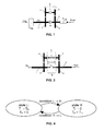
- Fig. 1 schematically represents a drive-line, i.e. the model of the drive-line according to the invention.
- This drive-line comprises two inertia components 1 and 2, a gear set G provided with an input shaft 7, an output shaft 8, gear wheels 3, 4, 5 and 6 constituting two gearings 3,4 and 5,6 as well as two friction elements L and H.
- Friction element L also denoted low clutch L, when engaged, i.e. activated, connects the said inertia components 1 and 2 through the gear set G, while friction element H, also denoted high clutch H, when activated connects the said inertia components 1 and 2 directly.
- an activated high clutch H thus realises a 1 to 1 transmission speed and torque ratio
- a transmission speed ratio i_gear is realised that depends on the gear ratio of the said two gearings 3, 4 and 5, 6.
- the output/input speed ratio of the first gearing 4, 3 is chosen equal to 1 and that of the second gearing 6,5 is defined as 1/z.
- the overall "low" speed ratio of the transmission thus also being equal to 1/z.
- the output/input torque ratio of the transmission of course being equal to z.
- Factor z is chosen larger than 1 throughout this example.
- Inertia 1 incorporates all inertia sub-components upstream of the clutches L and H, i.e. the inertia of the gear wheels 3 and 4, i.e. the input shaft 7 the engine and for example that of a torque converter, any other shafts and/or a continuously variable transmission (CVT) that may be included in the drive line.
- Inertia 2 incorporates all inertia sub-components downstream of the clutches L and H, i.e. the inertia of the gear wheels 5 and 6, the output shaft 8 and also includes the vehicle inertia.
- An engine torque T eng and a road load torque T load are respectively acting on inertia 1 and inertia 2.
- the engine torque T eng used in the drive-line model is the torque generated by the (combustion) engine or motor incorporated in the drive line. Often such engine torque T eng is estimated using electronic means based on different signals such as the rotational speed of the engine ⁇ eng , the amount of fuel supplied to the engine and the so-called spark advance angle.
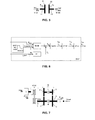
- the transmission speed ratio i_gear of the gear set G is changed according to a prescribed trajectory as a function of time t during the clutch-to-clutch shift, which trajectory is denoted here as i_gearset,.
- i_gearset trajectory has a parabolic-like shape, as indicated in figure 3 for a down shift.
- Such shape realises a fast paced ratio change early on in the shift, but such pace smoothly decreases to zero towards the completion of the gear shift.
- the actual speed ratio i_gear of the gear set G is forced to follow the set-point i_gearset(t) on the i_gearset trajectory by accelerating respectively decelerating inertia 1, also denoted J inp , relative to inertia 2, also denoted J veh , which in turn is effected by a controlled engagement of the clutches L and H.
- Fig. 2 defines the relevant torque levels and clutch torque capacities for a stepped automatic transmission embodied as the two stage gear set G comprising the two gearings 3,4 and 5,6, the low and high clutches L and H each having a friction or engagement element 9 or 10, alternatively denoted clutch plates 9, 10 are provided between the said gearings 3,4 and 5,6.
- T L and T H are the clutch torque capacities the low clutch L and the high clutch H respectively, i.e. the instantaneous torque level that may be transmitted by the respective clutch L, H.
- T H T in - T L ⁇ 0 which results in: T L ⁇ T in
- Fig. 3 illustrates a typical up shift at positive engine/input torque T eng , T in .
- the upper graph of Fig. 3 gives the instantaneously desired ratio i_gearset(t) of the gear set G versus, i.e. as a function of the passage of time t, whereby the x- or i_gearset-axis values increase towards the y- or time axis.
- Factor 1/z and 1 are the output/input speed ratios of the transmission respectively with the low clutch L engaged, i.e. coupling the transmission input shaft 7 with the output shaft 8 via the gear set G, and with the high clutch H engaged, i.e. realising a direct drive between the transmission input shaft 7 and output shaft 8.
- the manner in which the transmission speed ratio i_gear between the output shaft 8 and the input shaft 7 is to be changed during a down shift is prescribed, i.e. pre-programmed as the trajectory shown in the upper graph of Fig. 3.
- the same trajectory can also be prescribed for an up shift simply by replacing 1/z by 1 and 1, whereby the x- or i_gearset-axis values decrease towards the y- or time axis.
- the middle graph shows the engine torque T eng as the smooth line and the gear set G input torque T in as the marked line both versus time t.
- the engine torque T eng is maintained at a constant level during the entire gear shift.
- the input torque T in no longer equals the engine torque T eng , because of a positive torque generated in the drive line due to the deceleration of the input inertia J inp , inertia 1, during the gear shift.
- the bottom graph shows the low clutch L torque capacity T L as the smooth line and the high clutch H torque capacity T H as the marked line both versus time t.
- the clutch torque algorithm according to the present invention prescribes that before the gear shift is initiated the low clutch L torque capacity T L is equal to the input torque T in , whereas the high clutch H torque capacity T H is equal to zero.
- the clutch torque algorithm prescribes that the low clutch L torque capacity T L is to be controlled to zero, whereas the high clutch H torque capacity T H is to be controlled to correspond to the input torque T in .
- This phase of the gear shift action is the so called torque phase TP, which is performed in advance of effecting the actual changing of the transmission speed ratio, because only the high clutch H is able to transfer the positive input torque T in during the gear shift as was explained in the above.
- the said torque capacities T H and T L are controlled along linear trajectories.
- this such trajectory is a matter of choice and may be specifically adapted to suit the specific application of the transmission.
- the torque phase TP takes as little time as possible, so that the characteristics of the (electro/hydraulic) system for controlling the said torque capacities T H and T L will determine the optimum shape and maximum attainable angle of inclination of the said trajectories.
- the actual transmission speed ratio change takes place automatically by controlling the clutch torque capacity T H of the engaging high clutch H to coincide with the input torque T in in accordance with the invention.
- Fig. 4 shows the clutch torque algorithm according to the invention in terms of a state-machine.
- State L is active if the low clutch L is fully engaged or during gear shifts with negative input torque T in . In this state the input torque T in is transferred by the low clutch L alone.
- State H is active if the high clutch H is fully engaged or during up shifts or down shifts with positive input torque T in . In this state the input torque T in is transferred by the high clutch H alone. Note that these two states L, H are valid not only in steady state transmission operation, but also during the shift phase SP of the respective gear shift action.
- condition H ⁇ L is true, i.e. when a down shift is desired, then a transfer from state H to state L is initiated. Initiation of the transfer from the state L to state H takes place if condition L ⁇ H is true and an up shift is desired. Note that these transfers in fact represent the torque phase TP of the respective gear shift action.
- Fig. 5 provides a schematic representation of a clutch L, H, alternatively denoted friction element L, H.
- the low and high clutches L and H as commonly known in transmissions and in particular the clutch torque capacities T H and T L may be incorporated in the drive line model according to the invention by means of a relatively simple, but realistic model thereof.
- F N represents a clamping or engagement force that brings friction or clutch plates 9 and 10, which are associated with a clutch input shaft 11 and a clutch output shaft 12 respectively.
- Such force clamping force F N may be effected in a generally known fashion by a hydraulic clutch engagement pressure C P acting in a piston/cylinder assembly associated with at least one of the clutch plates 9, 10 of the clutch.
- engagement pressure C P may be generated and controlled also in a generally known fashion by means of a hydraulic pump and a, preferably electronically controllable, pressure control valve.
- T in and T out denote the torque transferred by the friction element L, H, i.e. between the clutch plates 9 and 10 and ⁇ in and ⁇ out respectively denote the rotational speed of the clutch input shaft 11 and the clutch output shaft 12.
- T L , T H may be calculated from:
- the coefficients of friction may be adapted during operation of the transmission, e.g. based on clutch engagement pressure C P versus clutch torque capacity T L , T H measurement, so as to be able to account for temperature, wear or other influence factors.
- Fig. 6 provides a block scheme of a drive line controller DLC operating in accordance with the control method according to the invention.
- This controller DLC comprises several blocks.
- the prescribed desired speed ratio versus time t trajectory i_gearset of the gear set G provides an instantaneously desired transmission speed ratio i_gearset(t).
- the gear set input torque T in is determined using the above-described drive-line model DLM according to the invention.
- the gear set input torque T in is subsequently used to determine the desired clutch torque capacities T L , T H in accordance with the gear set model GSM, i.e. the previously described clutch torque algorithm.
- a clutch model CLM e.g.
- actuator control signals I L , I H that are required to realise the said clamping forces F L and F H are determined in block CLA.
- These actuator control signals I L , I H are the output signal of the drive line controller DLC, which are fed to a suitable controller (not shown).
- these actuator control signals I L , I H will be electric currents used for operating electronically controllable pressure valves each controlling one respective clutch engagement pressures C P , which signals I L , I H may be obtained using a characteristic of the pressure valve that gives the dependency between the actuation signal fed to the valve and the pressure set in response thereto.
- a feed-back of the actually realised transmission speed ratio i_gear to the DLC may be incorporated in the control method based on measurement of the rotational speed of the transmission output shaft (8) and input shafts (7).
- this is preferably realised by generating a torque correction signal Tc in dependency on the difference between the instantaneously desired speed ratio i_gearset(t) and the actually realised transmission speed ratio i_gear, which torque correction signal Tc is added to the gear set input torque T in determined by the DLM.
- a generally known PID- or PI-controller may be applied for this purpose.
- the said difference between the actual and desired transmission ratio may be used in the adaptation of the DLC input signal representing the engine torque T eng signal or of the method employed in estimating the engine torque T eng .
- the drive-line comprises not only the gear set G, but also a continuously variable transmission CVT as indicated in figure 7 and if the transmission speed ratios of these two drive-line components are desired to be shifted simultaneously, the individual ratio shifts of the said two components may have to be performed in a controlled and mutually adapted manner to obtain a smoothly changing or possibly even a constant overall speed ratio between the said two inertia components 1 and 2. Since the clutch-to-clutch shift controller proposed in the above has been developed for this type of drive-line configuration, which is for example known from the European patent 0 787 927, it may be considered desirable that the overall output/input speed ratio ⁇ veh / ⁇ eng of the drive-line is virtually constant during the gear shift of the gear set G.
Landscapes
- Engineering & Computer Science (AREA)
- General Engineering & Computer Science (AREA)
- Mechanical Engineering (AREA)
- Control Of Transmission Device (AREA)
- Transmitters (AREA)
- Communication Control (AREA)
- Selective Calling Equipment (AREA)
Priority Applications (9)
| Application Number | Priority Date | Filing Date | Title |
|---|---|---|---|
| EP02076403A EP1353095A1 (en) | 2002-04-10 | 2002-04-10 | Control method for an automatic transmission |
| DE60304698T DE60304698T2 (de) | 2002-04-10 | 2003-04-08 | Steuerverfahren für ein automatisches getriebe |
| EP03745799A EP1497576B1 (en) | 2002-04-10 | 2003-04-08 | Control method for an automatic transmission |
| PCT/EP2003/003702 WO2003085288A1 (en) | 2002-04-10 | 2003-04-08 | Control method for an automatic transmission |
| US10/510,736 US7130733B2 (en) | 2002-04-10 | 2003-04-08 | Control method for an automatic transmission |
| AT03745799T ATE323854T1 (de) | 2002-04-10 | 2003-04-08 | Steuerverfahren für ein automatisches getriebe |
| CNB038081040A CN100357636C (zh) | 2002-04-10 | 2003-04-08 | 用于自动变速器的控制方法 |
| JP2003582438A JP4392856B2 (ja) | 2002-04-10 | 2003-04-08 | 自動変速機の制御方法 |
| AU2003226796A AU2003226796A1 (en) | 2002-04-10 | 2003-04-08 | Control method for an automatic transmission |
Applications Claiming Priority (1)
| Application Number | Priority Date | Filing Date | Title |
|---|---|---|---|
| EP02076403A EP1353095A1 (en) | 2002-04-10 | 2002-04-10 | Control method for an automatic transmission |
Publications (1)
| Publication Number | Publication Date |
|---|---|
| EP1353095A1 true EP1353095A1 (en) | 2003-10-15 |
Family
ID=28051820
Family Applications (2)
| Application Number | Title | Priority Date | Filing Date |
|---|---|---|---|
| EP02076403A Withdrawn EP1353095A1 (en) | 2002-04-10 | 2002-04-10 | Control method for an automatic transmission |
| EP03745799A Expired - Lifetime EP1497576B1 (en) | 2002-04-10 | 2003-04-08 | Control method for an automatic transmission |
Family Applications After (1)
| Application Number | Title | Priority Date | Filing Date |
|---|---|---|---|
| EP03745799A Expired - Lifetime EP1497576B1 (en) | 2002-04-10 | 2003-04-08 | Control method for an automatic transmission |
Country Status (8)
| Country | Link |
|---|---|
| US (1) | US7130733B2 (zh) |
| EP (2) | EP1353095A1 (zh) |
| JP (1) | JP4392856B2 (zh) |
| CN (1) | CN100357636C (zh) |
| AT (1) | ATE323854T1 (zh) |
| AU (1) | AU2003226796A1 (zh) |
| DE (1) | DE60304698T2 (zh) |
| WO (1) | WO2003085288A1 (zh) |
Families Citing this family (12)
| Publication number | Priority date | Publication date | Assignee | Title |
|---|---|---|---|---|
| US7693635B2 (en) * | 2006-03-22 | 2010-04-06 | Gm Global Technology Operations, Inc. | Method for learning the flow rate of hydraulic fluid in an automatic transmission |
| US7706949B2 (en) * | 2006-05-25 | 2010-04-27 | Gm Global Technology Operations, Inc. | Method and apparatus to control an electro-mechanical transmission during shifting event |
| US8494732B2 (en) * | 2007-11-04 | 2013-07-23 | GM Global Technology Operations LLC | Method for determining a preferred engine operation in a hybrid powertrain system during blended braking |
| JP2011528092A (ja) * | 2008-07-17 | 2011-11-10 | 兆▲ハン▼ 黄 | 一種の自動車ステップ自動変速器の変速方法 |
| US8738248B2 (en) * | 2008-10-21 | 2014-05-27 | Allison Transmission, Inc. | System for controlling vehicle overspeeding via control of one or more exhaust brake devices |
| DE102010014193C5 (de) * | 2009-11-05 | 2023-03-23 | Schaeffler Technologies AG & Co. KG | Verfahren zur Steuerung eines Doppelkupplungsgetriebes |
| JP5191978B2 (ja) * | 2009-11-18 | 2013-05-08 | ジヤトコ株式会社 | 自動変速機の制御装置 |
| DE102015120599B4 (de) | 2015-11-27 | 2017-06-22 | Iav Gmbh Ingenieurgesellschaft Auto Und Verkehr | Verfahren zur Lastschaltung von Automatgetrieben durch eine Doppelkupplungsstrategie mit Transformation |
| US20180320784A1 (en) | 2015-11-27 | 2018-11-08 | Iav Gmbh Ingenieurgesellschaft Auto Und Verkehr | Method for power shifting in hybrid automatic transmissions by means of a dual-clutch strategy involving transformation |
| DE102016111060B4 (de) | 2016-06-16 | 2019-08-01 | Iav Gmbh Ingenieurgesellschaft Auto Und Verkehr | Verfahren zur Lastschaltung von hybridisierten Automatgetrieben durch eine Doppelkupplungsstrategie mit Transformation |
| NL2018971B1 (en) * | 2017-05-24 | 2018-12-07 | Punch Powertrain Nv | a shifting method for a transmission, a transmission system, a computer program product, and a vehicle. |
| DE102021113457A1 (de) | 2021-05-25 | 2022-12-01 | Voith Patent Gmbh | Verfahren, System und Computerprogrammprodukt zum Herstellen eines Kraftschlusses zwischen einem Verbrennungsmotor und einem Automatikgetriebe aus einer Neutralstellung des Automatikgetriebes |
Citations (4)
| Publication number | Priority date | Publication date | Assignee | Title |
|---|---|---|---|---|
| US4282957A (en) * | 1978-10-09 | 1981-08-11 | Toyota Jidosha Kogyo Kabushiki Kaisha | Sub-transmission control system for providing engine braking |
| EP0670789A1 (de) | 1993-10-05 | 1995-09-13 | Robert Bosch Gmbh | Verfahren zur steuerung des abtriebsmoments eines automatischen schaltgetriebes |
| DE19741440A1 (de) * | 1997-09-19 | 1999-04-15 | Bayerische Motoren Werke Ag | Wechselgetriebe |
| US5950781A (en) * | 1996-08-08 | 1999-09-14 | Volkswagen Ag | Method for shifting a twin-clutch transmission and twin-clutch transmission arrangement |
Family Cites Families (33)
| Publication number | Priority date | Publication date | Assignee | Title |
|---|---|---|---|---|
| JPS6145163A (ja) * | 1984-08-10 | 1986-03-05 | Hitachi Ltd | 自動変速システム |
| US4790418A (en) * | 1987-04-30 | 1988-12-13 | Ford Motor Company | Transmission clutch loop transfer control |
| US5168449A (en) * | 1988-04-29 | 1992-12-01 | Chrysler Corporation | Method of calculating torque for an electronic automatic transmission system |
| US4935872A (en) * | 1988-04-29 | 1990-06-19 | Chrysler Corporation | Method of shift selection in an electronic automatic transmission system |
| DE68915361T2 (de) * | 1988-08-05 | 1994-08-25 | Honda Motor Co Ltd | Gerät zur Gangschaltungssteuerung in einem automatischen Getriebe. |
| US4936167A (en) * | 1989-03-09 | 1990-06-26 | Chrysler Corporation | Method of universally organizing shifts for an automatic transmission system |
| US5157608A (en) * | 1990-09-14 | 1992-10-20 | Ford Motor Company | Electronic control system for multiple ratio transmission including circuit pressure control |
| DE4031570C2 (de) * | 1990-10-05 | 1995-10-12 | Daimler Benz Ag | Anordnung zum selbsttätigen Schalten mittels Druckmittel-Hilfskraft eines Mehrwege-Zahnräderwechselgetriebes |
| US5519617A (en) * | 1993-05-07 | 1996-05-21 | Ford Motor Company | Torque managed traction control for the drive wheels of an automotive vehicle |
| US5722519A (en) * | 1994-10-14 | 1998-03-03 | Ford Global Technologies, Inc. | Multiple ratio automatic transmission and torque converter |
| US5646842A (en) * | 1994-10-14 | 1997-07-08 | Ford Motor Company | Shift control system for a multiple ratio automatic transmission |
| US5553694A (en) * | 1994-10-14 | 1996-09-10 | Ford Motor Company | Multiple ratio automatic transmission and torque converter |
| US5612874A (en) * | 1994-10-14 | 1997-03-18 | Ford Motor Company | Multiple ratio automatic transmission with solenoid operated valves for effecting pressure buildup |
| DE19511996C1 (de) * | 1995-03-31 | 1996-08-14 | Daimler Benz Ag | Verfahren zur selbsttätigen Steuerung einer Gangschaltung eines automatischen Stufengetriebes eines Kraftfahrzeuges |
| US5835875A (en) * | 1995-10-27 | 1998-11-10 | Ford Global Technologies, Inc. | Swap-shift control system for a multiple ratio transmission |
| US5802490A (en) * | 1996-02-20 | 1998-09-01 | Ford Global Technologies, Inc. | Torque converter regulator and clutch lockout system for an automotive vehicle |
| US5799260A (en) * | 1996-02-20 | 1998-08-25 | Ford Global Technologies, Inc. | System for controlling multiple hydraulic pumps in an automatic transmission |
| JP3334485B2 (ja) * | 1996-04-30 | 2002-10-15 | アイシン・エィ・ダブリュ株式会社 | 自動変速機の油圧制御装置 |
| JP3298423B2 (ja) * | 1996-09-19 | 2002-07-02 | アイシン・エィ・ダブリュ株式会社 | 自動変速機の油圧制御装置 |
| JP3385523B2 (ja) * | 1997-08-13 | 2003-03-10 | アイシン・エィ・ダブリュ株式会社 | 自動変速機の油圧制御装置 |
| JP3468051B2 (ja) * | 1997-09-04 | 2003-11-17 | アイシン・エィ・ダブリュ株式会社 | 自動変速機の油圧制御装置 |
| JP3407619B2 (ja) * | 1997-10-16 | 2003-05-19 | 株式会社デンソー | 自動変速機の制御装置及び自動変速機の制御方法並びに記憶媒体 |
| US6122583A (en) * | 1997-12-23 | 2000-09-19 | Ford Global Technologies, Inc. | Upshift and downshift control valve system for multiple ratio automatic transmission |
| US6649548B1 (en) * | 1998-10-02 | 2003-11-18 | Kimberly-Clark Worldwide, Inc. | Nonwoven web and film laminate with improved strength and method of making the same |
| US6269293B1 (en) * | 1998-12-14 | 2001-07-31 | Daimlerchrysler Corporation | Interactive engine and automatic transmission control |
| US6459980B1 (en) * | 1999-02-08 | 2002-10-01 | Toyota Jidosha Kabushiki Kaisha | Vehicle braked with motor torque and method of controlling the same |
| JP3294230B2 (ja) * | 2000-02-22 | 2002-06-24 | 株式会社日立製作所 | 自動車用制御装置,自動車の制御方法,変速機 |
| JP3785901B2 (ja) * | 2000-05-19 | 2006-06-14 | トヨタ自動車株式会社 | 無段変速機の変速制御装置 |
| US6574535B1 (en) * | 2000-05-31 | 2003-06-03 | General Motors Corporation | Apparatus and method for active driveline damping with clunk control |
| US6385520B1 (en) * | 2000-08-10 | 2002-05-07 | Ford Global Technologies, Inc. | Control strategy and method for independently controlling friction element actuators for an automatic transmission |
| US6278926B1 (en) * | 2000-09-18 | 2001-08-21 | Ford Global Technologies, Inc. | Adaptive electronic transmission control system and strategy for nonsynchronous automatic transmission |
| US6449548B1 (en) * | 2001-02-14 | 2002-09-10 | Ford Global Technologies, Inc. | Automatic transmission shift control |
| JP2002295663A (ja) * | 2001-03-30 | 2002-10-09 | Aisin Aw Co Ltd | 自動変速機の変速制御装置 |
-
2002
- 2002-04-10 EP EP02076403A patent/EP1353095A1/en not_active Withdrawn
-
2003
- 2003-04-08 WO PCT/EP2003/003702 patent/WO2003085288A1/en active IP Right Grant
- 2003-04-08 EP EP03745799A patent/EP1497576B1/en not_active Expired - Lifetime
- 2003-04-08 AT AT03745799T patent/ATE323854T1/de not_active IP Right Cessation
- 2003-04-08 AU AU2003226796A patent/AU2003226796A1/en not_active Abandoned
- 2003-04-08 JP JP2003582438A patent/JP4392856B2/ja not_active Expired - Fee Related
- 2003-04-08 DE DE60304698T patent/DE60304698T2/de not_active Expired - Lifetime
- 2003-04-08 CN CNB038081040A patent/CN100357636C/zh not_active Expired - Fee Related
- 2003-04-08 US US10/510,736 patent/US7130733B2/en not_active Expired - Fee Related
Patent Citations (4)
| Publication number | Priority date | Publication date | Assignee | Title |
|---|---|---|---|---|
| US4282957A (en) * | 1978-10-09 | 1981-08-11 | Toyota Jidosha Kogyo Kabushiki Kaisha | Sub-transmission control system for providing engine braking |
| EP0670789A1 (de) | 1993-10-05 | 1995-09-13 | Robert Bosch Gmbh | Verfahren zur steuerung des abtriebsmoments eines automatischen schaltgetriebes |
| US5950781A (en) * | 1996-08-08 | 1999-09-14 | Volkswagen Ag | Method for shifting a twin-clutch transmission and twin-clutch transmission arrangement |
| DE19741440A1 (de) * | 1997-09-19 | 1999-04-15 | Bayerische Motoren Werke Ag | Wechselgetriebe |
Non-Patent Citations (2)
| Title |
|---|
| ROESCH R ET AL: "DIE ELEKTRONISCHE STEUERUNG DES AUTOMATISCHEN GETRIEBES W5A 330/580VON MERCEDES-BENZ", ATZ AUTOMOBILTECHNISCHE ZEITSCHRIFT, FRANCKH'SCHE VERLAGSHANDLUNG. STUTTGART, DE, vol. 97, no. 11, 1 November 1995 (1995-11-01), pages 736 - 738,740,742,744-748, XP000541586, ISSN: 0001-2785 * |
| WAGNER G: "Doppelschaltungen bei Doppelkupplungsgetrieben", VDI BERICHTE, DUESSELDORF, DE, no. 1170, 1994, pages 119 - 135, XP008007821 * |
Also Published As
| Publication number | Publication date |
|---|---|
| CN100357636C (zh) | 2007-12-26 |
| WO2003085288A1 (en) | 2003-10-16 |
| JP2005522636A (ja) | 2005-07-28 |
| EP1497576B1 (en) | 2006-04-19 |
| JP4392856B2 (ja) | 2010-01-06 |
| ATE323854T1 (de) | 2006-05-15 |
| CN1646836A (zh) | 2005-07-27 |
| US7130733B2 (en) | 2006-10-31 |
| EP1497576A1 (en) | 2005-01-19 |
| DE60304698D1 (de) | 2006-05-24 |
| US20050228567A1 (en) | 2005-10-13 |
| DE60304698T2 (de) | 2006-11-16 |
| AU2003226796A1 (en) | 2003-10-20 |
Similar Documents
| Publication | Publication Date | Title |
|---|---|---|
| JP5790672B2 (ja) | 車両の変速制御装置 | |
| EP1674767B1 (en) | Swap shift control | |
| JP6015757B2 (ja) | 車両の変速制御装置 | |
| EP2226532B1 (en) | Control apparatus and method for automatic transmission | |
| EP0235892A1 (en) | Clutch-to-clutch power-on downshifting in a motor vehicle automatic transmission | |
| EP2228562B1 (en) | Control apparatus and method for automatic transmission | |
| EP1497576B1 (en) | Control method for an automatic transmission | |
| JPH0633816B2 (ja) | 自動変速機のトルク確立装置の作動方法 | |
| JP5724966B2 (ja) | 車両の変速制御装置 | |
| JP5790669B2 (ja) | 車両の変速制御装置 | |
| JP2014137119A (ja) | 車両の変速制御装置 | |
| JP5991165B2 (ja) | 車両の変速制御装置 | |
| JP5949938B2 (ja) | 車両の変速制御装置 | |
| JP2014137103A (ja) | 車両の変速制御装置 | |
| JP2014137104A (ja) | 車両の変速制御装置 | |
| CN110056649B (zh) | 变速器控制 | |
| JP2641007B2 (ja) | 車両用自動変速機の変速制御装置 | |
| JPH06307524A (ja) | 自動変速機の変速制御装置 | |
| JPH0634023A (ja) | 車両用自動変速機の変速制御装置 | |
| JPH06207656A (ja) | 自動変速機の変速制御方法 | |
| EP1411277A1 (en) | Gearshift control method for an automatic transmission and automatic transmission operated in accordance therewith | |
| JP2014137102A (ja) | 車両の変速制御装置 | |
| JPS6124864A (ja) | 車輌用自動変速機の変速制御方法 |
Legal Events
| Date | Code | Title | Description |
|---|---|---|---|
| PUAI | Public reference made under article 153(3) epc to a published international application that has entered the european phase |
Free format text: ORIGINAL CODE: 0009012 |
|
| AK | Designated contracting states |
Kind code of ref document: A1 Designated state(s): AT BE CH CY DE DK ES FI FR GB GR IE IT LI LU MC NL PT SE TR |
|
| AX | Request for extension of the european patent |
Extension state: AL LT LV MK RO SI |
|
| 17P | Request for examination filed |
Effective date: 20040120 |
|
| GRAP | Despatch of communication of intention to grant a patent |
Free format text: ORIGINAL CODE: EPIDOSNIGR1 |
|
| AKX | Designation fees paid |
Designated state(s): AT BE CH CY DE DK ES FI FR GB GR IE IT LI LU MC NL PT SE TR |
|
| GRAS | Grant fee paid |
Free format text: ORIGINAL CODE: EPIDOSNIGR3 |
|
| STAA | Information on the status of an ep patent application or granted ep patent |
Free format text: STATUS: THE APPLICATION IS DEEMED TO BE WITHDRAWN |
|
| 18D | Application deemed to be withdrawn |
Effective date: 20040813 |