EP1353084A2 - Scheibenbremse mit Federrücklauf - Google Patents
Scheibenbremse mit Federrücklauf Download PDFInfo
- Publication number
- EP1353084A2 EP1353084A2 EP03252275A EP03252275A EP1353084A2 EP 1353084 A2 EP1353084 A2 EP 1353084A2 EP 03252275 A EP03252275 A EP 03252275A EP 03252275 A EP03252275 A EP 03252275A EP 1353084 A2 EP1353084 A2 EP 1353084A2
- Authority
- EP
- European Patent Office
- Prior art keywords
- spring
- engagement
- backing plate
- moment
- brake pad
- Prior art date
- Legal status (The legal status is an assumption and is not a legal conclusion. Google has not performed a legal analysis and makes no representation as to the accuracy of the status listed.)
- Granted
Links
Images

Classifications
-
- F—MECHANICAL ENGINEERING; LIGHTING; HEATING; WEAPONS; BLASTING
- F16—ENGINEERING ELEMENTS AND UNITS; GENERAL MEASURES FOR PRODUCING AND MAINTAINING EFFECTIVE FUNCTIONING OF MACHINES OR INSTALLATIONS; THERMAL INSULATION IN GENERAL
- F16D—COUPLINGS FOR TRANSMITTING ROTATION; CLUTCHES; BRAKES
- F16D65/00—Parts or details
- F16D65/02—Braking members; Mounting thereof
- F16D65/04—Bands, shoes or pads; Pivots or supporting members therefor
- F16D65/092—Bands, shoes or pads; Pivots or supporting members therefor for axially-engaging brakes, e.g. disc brakes
- F16D65/095—Pivots or supporting members therefor
- F16D65/097—Resilient means interposed between pads and supporting members or other brake parts
- F16D65/0973—Resilient means interposed between pads and supporting members or other brake parts not subjected to brake forces
Definitions
- the present invention is directed to a return spring for pads in a disc brake system and, in particular, to a return spring with engagement legs that apply a torque to maintain the pads generally parallel to the rotor when in a non-braking state.
- FIG. 1 is a partial top view 10 of a typical disc brake assembly wherein a v-shaped spring 1 is positioned between backing plates 3 that support friction pads 5.
- the v-shaped spring 1 exerts an outward force "F" on the pads 5 to urge each pad 5 away from respective outer surfaces 8 of the rotor 7, thus preventing drag, excessive pad wear, and excessive rotor wear during the non-braking condition.
- FIG 2 illustrates the spring 1 in a typical installation and shows one of two opposed ears 9 that are commonly used to carry the backing plate.
- the ears 9 ride in a recess 12 in the mounting member 14.
- Engagement legs 11 at the end of each spring member 13 engage openings 15 in the backing plates 3.
- the engagement legs 11 are perpendicular to the spring member 13.
- the engagement leg 11 is generally parallel to the opposing sides of the opening 15.
- Figure 5 illustrates a problem created by the return spring shown in Figures 1-4.
- the forces applied by the spring 13 to the upper parts of the backing plates 3 create a torque that rotates the pads about the ears 9 when the system is in a non-braking state.
- the plates 3 rotate about a longitudinal axis "M" of the plate (see Figure 2) that extends in a tangential direction (with respect to the brake rotor) between the ears 9, which causes the pads 5 to assume a non-parallel configuration with respect to the rotor 7, whereby the bottoms of the pads often contact the rotor 7 in the areas 16 resulting in uneven pad wear and excessive drag.
- the invention responds to this need by providing a uniquely configured disc brake pad return spring that applies a force urging the pads away from the rotor and also applies a twisting force that prevents the rotation about the backing plate ears normally caused by the return spring force.
- Another object of the invention is to provide a disc brake pad return spring that not only urges the pads away from the rotor in the non-braking state but also maintains a parallel alignment between the pads and the rotor.
- Yet another object of the invention is to provide an improved disc brake assembly that utilizes the inventive disc brake return spring.
- a further object is to provide a method of maintaining friction pads in a generally parallel orientation with respect to a rotor when in a non-braking state by inducing a first moment that opposes the moment induced in the backing plate by the return spring.
- the invention includes a disc brake pad return spring, the spring in combination with a disc brake assembly, and a method of counteracting the torque or rotation that is caused by the return spring when the brake pads are in the non-braking state.
- the return spring of the invention is configured such that it applies a torque that counteracts the torque normally created by application of the return force to the backing plate at a location displaced from a longitudinal axis that extends between the mounting ears.
- the return spring comprises a pair of spring members that together form a v-shape, and each spring member terminates in an engagement leg that extends at an angle to the respective spring leg such that the two legs diverge from each other.
- the engagement legs are received in holes in the backing plates in such a manner that the desired torque is applied to the backing plate.
- the two engagement legs lie in a plane transverse to a plane containing the spring members.
- the engagement legs are not parallel, however, and diverge at an angle that will place the spring members in torsion and apply a desired moment to each backing plate when engaged therewith.
- the plane containing the engagement ends may be perpendicular to the plane containing the spring members or not. Further, the spring may be symmetrical or not.
- the return spring also forms part of a brake pad assembly that includes a pair of friction pads mounted to a pair of backing plates, and a rotor. Each engagement leg is positioned in a respective hole in a backing plate of the assembly so that the spring legs force the friction pads away from the rotors when in a non-braking state.
- the inventive return spring applies a torque to maintain the pair of friction pads mounted on their respective backing plates generally parallel to the rotor when in a non-braking condition.
- the return spring applies a linea r outward force at a top portion of backing plates.
- the engagement legs induce a moment at the top portion of the backing plates. This moment counteracts the moment that is induced in the backing plates ears as a result of the application of the return force at a location spaced from the axis of the support ears.
- the present invention offers significant improvements in the operation of disc brake assemblies and longevity of brake components such as friction pads and rotors. Unlike many prior art disc brake assemblies, use of the inventive disc brake return spring maintains the friction pads in a generally parallel relationship with the rotor when at rest and in a non-braking state. Consequently, unwanted contact between the pads and rotors in the non-braking condition is eliminated or at least drastically reduced.
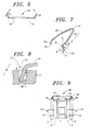
- one embodiment of the inventive return spring is designated by the reference numeral 20 and includes a pair of spring members 21 that are joined by a connector portion 23. Each spring member terminates in an engagement leg 25 with a free end 27. Each engagement leg 25 is bent outward to form an angle ⁇ as shown in Figures 6 and 7, measured in a plane containing the two engagement legs and with respect to a line perpendicular to the plane containing the two spring members 21. It will be appreciated that the engagement legs 11 of the prior art design of Figure 3 are parallel, whereas those of the invention diverge. Each leg 25 and its adjacent spring member 21 lie in a plane, and the leg 25 forms an angle ⁇ in that plane (see Figure 7) that may be more than 90°.
- the orientation of the engagement legs 25 may be defined with respect to different reference lines, such as axes "y” and “z” shown in Figure 7, or a component of the brake assembly such as the rotor surface 8 or a wall of the opening 15 in the backing plate.
- the angle ⁇ is defined herein as lying in the plane containing both engagement legs, e.g., the plane formed by a "y" axis perpendicular to the plane containing the spring members and "z" axis lying in both the plane containing the spring members and the plane containing the engagement legs.
- the angle ⁇ is measured in the y-z plane from the y-axis.
- the directions of the engagement legs intersect in the y-z plane, and the "y" axis extends in the direction of the bisector of the angle of intersection.
- the angle ⁇ is one half the angle of intersection.
- Figure 8 is an illustration of the engagement leg 25 received in opening 15 in one of the backing plates 3. Before being placed in the hole, the ends of the engagement legs are rotated toward each other to reduce the angles ⁇ and thereby apply a torque to each of the spring members. Thus, when engaged in the hole, the leg 25 assumes an angle ⁇ '.
- the angle ⁇ ' is determined by the geometry of the hole and the engagement leg. If the diameter of the hole is the common 2.4mm, the diameter of the spring member is the common 1.7mm, and the length of the engagement leg is 5.4mm, ⁇ ' will be about 7.4°.
- the spring members 21 apply a force to the backing plates through the legs 25 urging the backing plates 3 and the attached friction pads 5 away from the rotor 7. Because this force is applied at a distance from the longitudinal axis "M" formed by the ears of the backing plates, it generates a moment about that axis, tending to rotate the backing plate about the axis.
- Figure 9 illustrates the advantages of the invention, wherein the friction pads 5 and plates 3 are in the at-rest state and are generally parallel to the rotor 7. Bending the legs 25 outwardly by angle ⁇ in the rest state (i.e., the free ends 27 diverge with respect to each other in the at -rest state, see Figures 6 and 7) causes the spring leg to act both as a spring to produce the outward linear force "F” and as a torsion spring along length "L” to induce a moment "M” (see Figure 9) to the top of the backing plate.
- the dimensions of the spring leg 25 and opening 15 are sized such that this moment overcomes the moment resulting from application of the spring return force to the top of the pad on the one hand and the frictional resistance to sliding of the ears on the other.
- the torsion applied by the legs 25 force the bottom of the pad to slide away from the rotor 7 to provide clearance between the rotor 7 and the pads 5 in the parallel orientation shown in Figure 9.
- the angle ⁇ is about 15° so that each of the spring members is subjected to a torsion pre-load of about 8° to thereby apply the desired moment of about 1.7 in. -lbs. to each of the brake pads.
- This is only an illustration, however, and depends on such factors as the modulus of elasticity and spring constant of the material, and the diameter of the spring.
- the required angular displacement ⁇ can be calculated.
- the desired angle may be in the range of from 10 ° to 30°.
- the v-shaped spring is shown with a simple v-shape via the connector portion 23, other shapes could be employed for the spring members 21, such as a double V-shape as disclosed in JP-56-21633, or other curved shapes as would be within the skill of the art.
- the spring 20 can be made from any conventional spring material. Further, it can have a circular cross section, or any other cross sectional shape as would be within the skill of the art.
- connection between the spring and the backing plate may vary also and is not limited to the preferred engagement shown.
- the engagement leg may be differently configured, and the backing plate could include a protrusion received in a recess in the spring, or the spring could be attached to the backing plate by another connector such as a threaded screw, or the like.
Landscapes
- Engineering & Computer Science (AREA)
- General Engineering & Computer Science (AREA)
- Mechanical Engineering (AREA)
- Braking Arrangements (AREA)
Applications Claiming Priority (4)
| Application Number | Priority Date | Filing Date | Title |
|---|---|---|---|
| US199063 | 1988-05-26 | ||
| US37112702P | 2002-04-10 | 2002-04-10 | |
| US371127P | 2002-04-10 | ||
| US10/199,063 US7467693B2 (en) | 2002-04-10 | 2002-07-22 | Disc brake pad return spring |
Publications (3)
| Publication Number | Publication Date |
|---|---|
| EP1353084A2 true EP1353084A2 (de) | 2003-10-15 |
| EP1353084A3 EP1353084A3 (de) | 2004-01-28 |
| EP1353084B1 EP1353084B1 (de) | 2006-05-31 |
Family
ID=28456803
Family Applications (1)
| Application Number | Title | Priority Date | Filing Date |
|---|---|---|---|
| EP03252275A Expired - Lifetime EP1353084B1 (de) | 2002-04-10 | 2003-04-10 | Scheibenbremse mit Federrücklauf |
Country Status (4)
| Country | Link |
|---|---|
| US (1) | US7467693B2 (de) |
| EP (1) | EP1353084B1 (de) |
| JP (1) | JP2003314596A (de) |
| DE (1) | DE60305561T2 (de) |
Cited By (3)
| Publication number | Priority date | Publication date | Assignee | Title |
|---|---|---|---|---|
| CN104819229A (zh) * | 2015-05-18 | 2015-08-05 | 安徽江淮汽车股份有限公司 | 一种定钳盘式制动器 |
| WO2019140288A1 (en) * | 2018-01-12 | 2019-07-18 | Performance Friction Corporation | Torsion brake retractor, caliper and method |
| US11209057B2 (en) | 2018-01-12 | 2021-12-28 | Performance Friction Corporation | Torsion brake retractor, caliper and method |
Families Citing this family (22)
| Publication number | Priority date | Publication date | Assignee | Title |
|---|---|---|---|---|
| DE102004062731A1 (de) * | 2004-06-04 | 2005-12-29 | Continental Teves Ag & Co. Ohg | Scheibenbremse mit Federanordung |
| US8397880B2 (en) * | 2010-05-27 | 2013-03-19 | Akebono Brake Corporation | Pad retraction device |
| US8393441B2 (en) | 2011-01-24 | 2013-03-12 | Akebono Brake Corporation | Spreader spring |
| US8376092B2 (en) | 2011-02-10 | 2013-02-19 | Akebono Brake Corp. | Pad retraction device |
| JP5726151B2 (ja) * | 2012-11-08 | 2015-05-27 | 日信工業株式会社 | 車両用ディスクブレーキ |
| US9261152B2 (en) | 2013-05-14 | 2016-02-16 | Akebono Brake Corporation | Coiled spreader spring |
| CN104747633A (zh) * | 2014-07-24 | 2015-07-01 | 宋鲁江 | 汽车刹车片和刹车盘的分离装置 |
| DE202016102686U1 (de) * | 2015-06-15 | 2016-06-23 | Knorr-Bremse Systeme für Nutzfahrzeuge GmbH | Scheibenbremse für ein Nutzfahrzeug und Bremsbelagsatz |
| CN105697612B (zh) * | 2016-04-12 | 2018-06-26 | 张泽辉 | 一种用于摩托车碟刹泵的弹片 |
| CN109654135B (zh) * | 2016-06-18 | 2020-09-01 | 浙江展翔汽摩配有限公司 | 一种碟刹制动片簧 |
| MX2019000764A (es) | 2016-07-21 | 2019-06-12 | Preferred Tool & Die Inc | Hardware de mordaza que provee separacion entre pastilla y rotor. |
| DE102017222639A1 (de) | 2017-01-31 | 2018-08-02 | Continental Teves Ag & Co. Ohg | Festsattelkraftfahrzeugteilbelagscheibenbremse mit einer Stahlblechbügellüftspielfeder |
| FR3067688B1 (fr) * | 2017-06-19 | 2019-08-09 | Faiveley Transport Amiens | Systeme de freinage ferroviaire pour vehicule ferroviaire |
| US10871197B2 (en) | 2017-10-13 | 2020-12-22 | Akebono Brake Industry Co., Ltd | Brake pad retraction device |
| US20190234472A1 (en) | 2018-01-26 | 2019-08-01 | Akebono Brake Industry Co., Ltd. | Retraction spring |
| US10968967B2 (en) | 2018-11-12 | 2021-04-06 | Akebono Brake Industry Co., Ltd. | Brake retraction spring assembly |
| USD878984S1 (en) | 2018-11-15 | 2020-03-24 | Preferred Tool & Die, Inc. | Brake caliper hardware |
| US11971077B2 (en) | 2018-12-18 | 2024-04-30 | Volvo Truck Corporation | Wheel brake arrangement |
| US11143255B2 (en) * | 2019-05-09 | 2021-10-12 | Arvinmeritor Technology, Llc | Brake assembly having a retraction spring and method of assembly |
| USD928674S1 (en) | 2020-01-08 | 2021-08-24 | Preferred Tool & Die, Inc. | Brake caliper hardware |
| EP4317735B1 (de) | 2022-08-02 | 2024-10-30 | KNORR-BREMSE Systeme für Nutzfahrzeuge GmbH | Bremszangenanordnung für eine bremsscheibe einer bremsanlage für ein fahrzeug und bremsanlage |
| DE102022123484A1 (de) * | 2022-09-14 | 2024-03-14 | Knorr-Bremse Systeme für Nutzfahrzeuge GmbH | Scheibenbremse für ein Nutzfahrzeug |
Family Cites Families (19)
| Publication number | Priority date | Publication date | Assignee | Title |
|---|---|---|---|---|
| JPS5860032A (ja) | 1982-08-25 | 1983-04-09 | 東レ株式会社 | 嵩高糸の製造方法 |
| US4666025A (en) | 1985-05-02 | 1987-05-19 | Magnetic Power Systems, Inc. | Retraction means for friction members in friction coupling brakes and clutches |
| US4940119A (en) | 1987-11-30 | 1990-07-10 | Aisin Seiki Kabushiki Kaisha | Disc brake assembly |
| JP2901362B2 (ja) | 1991-03-01 | 1999-06-07 | トキコ株式会社 | ディスクブレーキ |
| DE4115635A1 (de) * | 1991-05-14 | 1992-11-19 | Teves Gmbh Alfred | Schwimmsattel-scheibenbremse, insbesondere fuer kraftfahrzeuge |
| GB2257483B (en) * | 1991-06-20 | 1995-04-26 | Tokico Ltd | Disk brake with return spring |
| JPH07506415A (ja) * | 1992-01-28 | 1995-07-13 | アイティーティー・オートモーティブ・ヨーロップ・ゲーエムベーハー | ブレーキシューのための拡張ばねを有するフローティングキャリパ式ディスクブレーキ |
| JP2552633Y2 (ja) * | 1992-03-27 | 1997-10-29 | トキコ株式会社 | ディスクブレーキ |
| JPH05346125A (ja) | 1992-06-15 | 1993-12-27 | Aisin Seiki Co Ltd | 車両用ディスクブレーキ |
| DE4304616A1 (de) | 1993-02-16 | 1994-08-18 | Daimler Benz Ag | Scheibenbremse für die Räder eines Kraftfahrzeuges |
| JP3383864B2 (ja) | 1994-03-31 | 2003-03-10 | トキコ株式会社 | ディスクブレーキ |
| US5549181A (en) * | 1994-09-13 | 1996-08-27 | Kelsey-Hayes Company | Brake shoe retractor clip for disc brake assembly |
| JPH08128475A (ja) * | 1994-11-01 | 1996-05-21 | Sumitomo Electric Ind Ltd | ディスクブレーキ用パッド戻しスプリング |
| JPH08145089A (ja) * | 1994-11-24 | 1996-06-04 | Sumitomo Electric Ind Ltd | ディスクブレーキ |
| FR2735195B1 (fr) | 1995-06-08 | 1998-01-30 | Alliedsignal Europ Services | Frein a disque utilisant un patin sollicite en rotation |
| EP0794349B1 (de) * | 1996-03-06 | 2001-06-13 | Aisin Seiki Kabushiki Kaisha | Scheibenbremssattel |
| DE19626299A1 (de) | 1996-07-01 | 1998-01-08 | Teves Gmbh Alfred | Federanordnung für eine Schwimmsattelscheibenbremse |
| JP3273436B2 (ja) * | 1996-07-09 | 2002-04-08 | トキコ株式会社 | ディスクブレーキ |
| US6378665B1 (en) * | 2000-06-30 | 2002-04-30 | Kelsey-Hayes Company | Pad retraction spring for disc brake assembly |
-
2002
- 2002-07-22 US US10/199,063 patent/US7467693B2/en not_active Expired - Fee Related
-
2003
- 2003-04-10 EP EP03252275A patent/EP1353084B1/de not_active Expired - Lifetime
- 2003-04-10 DE DE60305561T patent/DE60305561T2/de not_active Expired - Fee Related
- 2003-04-10 JP JP2003106641A patent/JP2003314596A/ja active Pending
Cited By (4)
| Publication number | Priority date | Publication date | Assignee | Title |
|---|---|---|---|---|
| CN104819229A (zh) * | 2015-05-18 | 2015-08-05 | 安徽江淮汽车股份有限公司 | 一种定钳盘式制动器 |
| WO2019140288A1 (en) * | 2018-01-12 | 2019-07-18 | Performance Friction Corporation | Torsion brake retractor, caliper and method |
| US11199232B2 (en) | 2018-01-12 | 2021-12-14 | Performance Friction Corporation | Torsion brake retractor, caliper and method |
| US11209057B2 (en) | 2018-01-12 | 2021-12-28 | Performance Friction Corporation | Torsion brake retractor, caliper and method |
Also Published As
| Publication number | Publication date |
|---|---|
| US7467693B2 (en) | 2008-12-23 |
| DE60305561D1 (de) | 2006-07-06 |
| EP1353084B1 (de) | 2006-05-31 |
| EP1353084A3 (de) | 2004-01-28 |
| US20030192749A1 (en) | 2003-10-16 |
| DE60305561T2 (de) | 2007-05-16 |
| JP2003314596A (ja) | 2003-11-06 |
Similar Documents
| Publication | Publication Date | Title |
|---|---|---|
| US7467693B2 (en) | Disc brake pad return spring | |
| US5022500A (en) | Disc brake caliper | |
| EP2992238B1 (de) | Scheibenbremse mit stabilisierten bremsbelägen und zugehörige verfahren zur montage und zum austausch eines belags | |
| CN111911568B (zh) | 具有回缩弹簧的制动器组件以及组装方法 | |
| US5875873A (en) | Air disc brake anti-rattle design | |
| EP1030078A2 (de) | Kettenspanner mit Blattfeder | |
| JP4156516B2 (ja) | ディスクブレーキパッドに予荷重するための板ばね | |
| KR840002250B1 (ko) | 슬라이딩 캘리퍼 디스크 브레이크 | |
| KR960706030A (ko) | 부동 캘리퍼 디스크 브레이크용 브레이크 패드 세트(set of brake pads for floating-caliper disc brake) | |
| JP6982493B2 (ja) | パッドクリップ、パッドクリップと戻しばねとの組立体、及びフローティング型ディスクブレーキ | |
| KR970005073B1 (ko) | 브레이크 패드 | |
| SE445946B (sv) | Delbeleggskivbroms med flytande bromsbygel | |
| EP1717476A1 (de) | Belaghalteklammer | |
| US10968967B2 (en) | Brake retraction spring assembly | |
| EP0709592A2 (de) | Scheibenbremse | |
| US7475759B1 (en) | Disc brake | |
| US6772865B2 (en) | Brake shoe retainer clip | |
| JP7650779B2 (ja) | 固定体及び固定装置 | |
| KR950004791B1 (ko) | 스폿트형 디스크 브레이크 | |
| US6938739B2 (en) | Brake head positioner | |
| EP3742017A1 (de) | Fahrzeugscheibenbremse, drehlager für eine scheibenbremse und klemmkappe für eine scheibenbremse | |
| JPH0610240Y2 (ja) | ディスクブレーキにおけるパッドスプリング | |
| US5909785A (en) | Twin ramp brake pad reaction member | |
| WO2005012754A1 (en) | Disc brake calipers | |
| US20040069575A1 (en) | Independent springing guides for floating rotors |
Legal Events
| Date | Code | Title | Description |
|---|---|---|---|
| PUAI | Public reference made under article 153(3) epc to a published international application that has entered the european phase |
Free format text: ORIGINAL CODE: 0009012 |
|
| AK | Designated contracting states |
Kind code of ref document: A2 Designated state(s): AT BE BG CH CY CZ DE DK EE ES FI FR GB GR HU IE IT LI LU MC NL PT RO SE SI SK TR |
|
| AX | Request for extension of the european patent |
Extension state: AL LT LV MK |
|
| PUAL | Search report despatched |
Free format text: ORIGINAL CODE: 0009013 |
|
| AK | Designated contracting states |
Kind code of ref document: A3 Designated state(s): AT BE BG CH CY CZ DE DK EE ES FI FR GB GR HU IE IT LI LU MC NL PT RO SE SI SK TR |
|
| AX | Request for extension of the european patent |
Extension state: AL LT LV MK |
|
| RIC1 | Information provided on ipc code assigned before grant |
Ipc: 7F 16D 65/54 A Ipc: 7F 16D 65/097 B |
|
| 17P | Request for examination filed |
Effective date: 20040519 |
|
| AKX | Designation fees paid |
Designated state(s): DE ES FR GB IT |
|
| 17Q | First examination report despatched |
Effective date: 20041013 |
|
| GRAP | Despatch of communication of intention to grant a patent |
Free format text: ORIGINAL CODE: EPIDOSNIGR1 |
|
| GRAJ | Information related to disapproval of communication of intention to grant by the applicant or resumption of examination proceedings by the epo deleted |
Free format text: ORIGINAL CODE: EPIDOSDIGR1 |
|
| GRAP | Despatch of communication of intention to grant a patent |
Free format text: ORIGINAL CODE: EPIDOSNIGR1 |
|
| GRAS | Grant fee paid |
Free format text: ORIGINAL CODE: EPIDOSNIGR3 |
|
| GRAA | (expected) grant |
Free format text: ORIGINAL CODE: 0009210 |
|
| AK | Designated contracting states |
Kind code of ref document: B1 Designated state(s): DE ES FR GB IT |
|
| PG25 | Lapsed in a contracting state [announced via postgrant information from national office to epo] |
Ref country code: IT Free format text: LAPSE BECAUSE OF FAILURE TO SUBMIT A TRANSLATION OF THE DESCRIPTION OR TO PAY THE FEE WITHIN THE PRESCRIBED TIME-LIMIT;WARNING: LAPSES OF ITALIAN PATENTS WITH EFFECTIVE DATE BEFORE 2007 MAY HAVE OCCURRED AT ANY TIME BEFORE 2007. THE CORRECT EFFECTIVE DATE MAY BE DIFFERENT FROM THE ONE RECORDED. Effective date: 20060531 |
|
| REG | Reference to a national code |
Ref country code: GB Ref legal event code: FG4D |
|
| REF | Corresponds to: |
Ref document number: 60305561 Country of ref document: DE Date of ref document: 20060706 Kind code of ref document: P |
|
| ET | Fr: translation filed | ||
| PGFP | Annual fee paid to national office [announced via postgrant information from national office to epo] |
Ref country code: GB Payment date: 20070313 Year of fee payment: 5 |
|
| PLBE | No opposition filed within time limit |
Free format text: ORIGINAL CODE: 0009261 |
|
| STAA | Information on the status of an ep patent application or granted ep patent |
Free format text: STATUS: NO OPPOSITION FILED WITHIN TIME LIMIT |
|
| 26N | No opposition filed |
Effective date: 20070301 |
|
| PGFP | Annual fee paid to national office [announced via postgrant information from national office to epo] |
Ref country code: IT Payment date: 20070802 Year of fee payment: 5 |
|
| PGFP | Annual fee paid to national office [announced via postgrant information from national office to epo] |
Ref country code: FR Payment date: 20070730 Year of fee payment: 5 |
|
| GBPC | Gb: european patent ceased through non-payment of renewal fee |
Effective date: 20080410 |
|
| REG | Reference to a national code |
Ref country code: FR Ref legal event code: ST Effective date: 20081231 |
|
| PG25 | Lapsed in a contracting state [announced via postgrant information from national office to epo] |
Ref country code: FR Free format text: LAPSE BECAUSE OF NON-PAYMENT OF DUE FEES Effective date: 20080430 |
|
| PG25 | Lapsed in a contracting state [announced via postgrant information from national office to epo] |
Ref country code: GB Free format text: LAPSE BECAUSE OF NON-PAYMENT OF DUE FEES Effective date: 20080410 Ref country code: ES Free format text: LAPSE BECAUSE OF NON-PAYMENT OF DUE FEES Effective date: 20070430 |
|
| PG25 | Lapsed in a contracting state [announced via postgrant information from national office to epo] |
Ref country code: IT Free format text: LAPSE BECAUSE OF NON-PAYMENT OF DUE FEES Effective date: 20080410 |
|
| PGFP | Annual fee paid to national office [announced via postgrant information from national office to epo] |
Ref country code: DE Payment date: 20090829 Year of fee payment: 7 |
|
| PG25 | Lapsed in a contracting state [announced via postgrant information from national office to epo] |
Ref country code: DE Free format text: LAPSE BECAUSE OF NON-PAYMENT OF DUE FEES Effective date: 20101103 |