EP1352691A2 - Rotationskopf mit Verschlussleisten - Google Patents
Rotationskopf mit Verschlussleisten Download PDFInfo
- Publication number
- EP1352691A2 EP1352691A2 EP03007191A EP03007191A EP1352691A2 EP 1352691 A2 EP1352691 A2 EP 1352691A2 EP 03007191 A EP03007191 A EP 03007191A EP 03007191 A EP03007191 A EP 03007191A EP 1352691 A2 EP1352691 A2 EP 1352691A2
- Authority
- EP
- European Patent Office
- Prior art keywords
- roller
- applicator head
- housing
- grooves
- roller slide
- Prior art date
- Legal status (The legal status is an assumption and is not a legal conclusion. Google has not performed a legal analysis and makes no representation as to the accuracy of the status listed.)
- Granted
Links
- 239000007788 liquid Substances 0.000 claims abstract description 27
- 239000000463 material Substances 0.000 claims abstract description 17
- 238000007789 sealing Methods 0.000 claims description 4
- 239000004831 Hot glue Substances 0.000 claims description 2
- 238000007599 discharging Methods 0.000 claims description 2
- 229920001169 thermoplastic Polymers 0.000 claims description 2
- 239000004416 thermosoftening plastic Substances 0.000 claims description 2
- 239000012530 fluid Substances 0.000 claims 1
- 238000005553 drilling Methods 0.000 abstract description 3
- 239000011248 coating agent Substances 0.000 abstract 4
- 238000000576 coating method Methods 0.000 abstract 4
- 239000000853 adhesive Substances 0.000 abstract 2
- 230000001070 adhesive effect Effects 0.000 abstract 2
- 239000012815 thermoplastic material Substances 0.000 abstract 2
- 239000007921 spray Substances 0.000 description 4
- 230000002411 adverse Effects 0.000 description 1
- 230000006835 compression Effects 0.000 description 1
- 238000007906 compression Methods 0.000 description 1
- 238000011109 contamination Methods 0.000 description 1
- 230000002349 favourable effect Effects 0.000 description 1
- 238000003475 lamination Methods 0.000 description 1
- 239000011344 liquid material Substances 0.000 description 1
- 238000005096 rolling process Methods 0.000 description 1
- 239000000758 substrate Substances 0.000 description 1
Images

Classifications
-
- B—PERFORMING OPERATIONS; TRANSPORTING
- B05—SPRAYING OR ATOMISING IN GENERAL; APPLYING FLUENT MATERIALS TO SURFACES, IN GENERAL
- B05C—APPARATUS FOR APPLYING FLUENT MATERIALS TO SURFACES, IN GENERAL
- B05C5/00—Apparatus in which liquid or other fluent material is projected, poured or allowed to flow on to the surface of the work
- B05C5/02—Apparatus in which liquid or other fluent material is projected, poured or allowed to flow on to the surface of the work the liquid or other fluent material being discharged through an outlet orifice by pressure, e.g. from an outlet device in contact or almost in contact, with the work
- B05C5/0245—Apparatus in which liquid or other fluent material is projected, poured or allowed to flow on to the surface of the work the liquid or other fluent material being discharged through an outlet orifice by pressure, e.g. from an outlet device in contact or almost in contact, with the work for applying liquid or other fluent material to a moving work of indefinite length, e.g. to a moving web
- B05C5/025—Apparatus in which liquid or other fluent material is projected, poured or allowed to flow on to the surface of the work the liquid or other fluent material being discharged through an outlet orifice by pressure, e.g. from an outlet device in contact or almost in contact, with the work for applying liquid or other fluent material to a moving work of indefinite length, e.g. to a moving web only at particular part of the work
-
- B—PERFORMING OPERATIONS; TRANSPORTING
- B05—SPRAYING OR ATOMISING IN GENERAL; APPLYING FLUENT MATERIALS TO SURFACES, IN GENERAL
- B05C—APPARATUS FOR APPLYING FLUENT MATERIALS TO SURFACES, IN GENERAL
- B05C5/00—Apparatus in which liquid or other fluent material is projected, poured or allowed to flow on to the surface of the work
- B05C5/02—Apparatus in which liquid or other fluent material is projected, poured or allowed to flow on to the surface of the work the liquid or other fluent material being discharged through an outlet orifice by pressure, e.g. from an outlet device in contact or almost in contact, with the work
- B05C5/027—Coating heads with several outlets, e.g. aligned transversally to the moving direction of a web to be coated
- B05C5/0275—Coating heads with several outlets, e.g. aligned transversally to the moving direction of a web to be coated flow controlled, e.g. by a valve
-
- B—PERFORMING OPERATIONS; TRANSPORTING
- B05—SPRAYING OR ATOMISING IN GENERAL; APPLYING FLUENT MATERIALS TO SURFACES, IN GENERAL
- B05C—APPARATUS FOR APPLYING FLUENT MATERIALS TO SURFACES, IN GENERAL
- B05C5/00—Apparatus in which liquid or other fluent material is projected, poured or allowed to flow on to the surface of the work
- B05C5/02—Apparatus in which liquid or other fluent material is projected, poured or allowed to flow on to the surface of the work the liquid or other fluent material being discharged through an outlet orifice by pressure, e.g. from an outlet device in contact or almost in contact, with the work
- B05C5/0225—Apparatus in which liquid or other fluent material is projected, poured or allowed to flow on to the surface of the work the liquid or other fluent material being discharged through an outlet orifice by pressure, e.g. from an outlet device in contact or almost in contact, with the work characterised by flow controlling means, e.g. valves, located proximate the outlet
- B05C5/0229—Apparatus in which liquid or other fluent material is projected, poured or allowed to flow on to the surface of the work the liquid or other fluent material being discharged through an outlet orifice by pressure, e.g. from an outlet device in contact or almost in contact, with the work characterised by flow controlling means, e.g. valves, located proximate the outlet the valve being a gate valve or a sliding valve
- B05C5/0233—Apparatus in which liquid or other fluent material is projected, poured or allowed to flow on to the surface of the work the liquid or other fluent material being discharged through an outlet orifice by pressure, e.g. from an outlet device in contact or almost in contact, with the work characterised by flow controlling means, e.g. valves, located proximate the outlet the valve being a gate valve or a sliding valve rotating valve, e.g. rotating perforated cylinder
Definitions
- the invention relates to a gun for applying liquid media such as liquefied thermoplastics or molten hot melt adhesives on a relatively movable to the application head material web, with a housing, with a roller chamber in the housing in which a roller slide can be driven in rotation is stored, and with a slot nozzle for discharging medium, the Roller slide is controllable and transversely to the direction of movement of the web extends.
- the gun can at a distance or in contact with the web be arranged.
- An applicator head of this type is known from DE 197 57 238 C2.
- the Roller slide formed axially parallel surface grooves, the order of produce liquid medium in line form transverse to the direction of movement of the web.
- Application heads of the aforementioned type are used in many applications always brought there where material webs for lamination on a Substrate to be prepared.
- material webs for lamination on a Substrate to be prepared To the specific consumption of liquid Medium to keep low and at the same time a very even distribution of
- an intermittent order is applied to a job image in raster form. If the material web rapportwise of a Knife is severed, the cuts must be between each two order lines be guided by liquid medium to stick to medium on the knife too prevent.
- the invention has the object, a gun of the to provide the above-mentioned type of a very selective line application ensures of liquid medium on webs.
- the surface grooves can be executed paraxial, this for first and second surface grooves and, accordingly, for the Closing strips applies.
- the first surface grooves form curved lines and in particular forming closed polylines
- the second surface grooves can be adapted in addition to the termination strips to these lines and in particular larger areas inside and outside the said closed Cover the lines on the cylinder surface of the roller slide.
- the large-area second surface grooves may optionally also Record multi-part closure strips.
- An inventive applicator head has the advantage that the control of the medium at the inlets to the feeders with clean tears through the Closure strips takes place, so that the accuracy of the metering not by the Toughness of the medium or the elasticity of the medium is adversely affected.
- the representation of grid points transverse to the direction of movement of the web can by using a corresponding nozzle orifice with individual holes in small Distance to be generated in the slot nozzle. Preferably each communicates a single feed in the housing with a single hole in the nozzle orifice. If the use of such a nozzle diaphragm is dispensed with, arises when using of axially parallel grooves a line order each transverse to the direction of movement the material web.
- At least one end of the housing has a radial Hole provided in the housing and an annular channel between the roller valve and Roll chamber formed, which is connected to the bore in the housing and it are radial supply holes in the roller slide in the plane of the annular channel executed, which are connected to the inner cavity and as a supply for medium serve.
- Said at least one annular channel can by an annular groove in the Roll surface and / or by a circumferential groove in the roller chamber bore be formed.
- the roller slide is at least one axial provided from the housing escaping pin, in which carried out an axial bore which is connected to the inner cavity and as a feeder for medium serves to the inner cavity.
- a supply of medium to the inner cavity takes place only at one or both ends of the roller slide can, for Compensation of a small pressure loss in the medium over the roller slide length a corresponding small increase in the diameter of the radial exit holes be provided to the surface grooves on the roller slide length.
- a leakage of medium from the housing may be due to the use of conventional Shaft seals at the ends of the roller slide against the roller chamber be prevented.
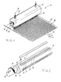
- Figure 1 shows an applicator head 11 of elongated cubic shape. From the case 12 of the applicator head 11 protrudes one end of a roller slide 13. The direction of rotation the roller slide 13 is indicated by an arrow 14. The end of the Roller slide 13 has a pin 15. On the housing 12 nozzles 16 are attached, via which, as indicated by arrows 17, liquid medium is supplied. At the bottom of the housing 12, a slot nozzle 18 can be seen, from which a spray curtain 19 exit. The spray curtain 19 strikes a material web 22 whose direction of movement is symbolized by an arrow 23. The spray curtain 19 generates a job grid 24 on the material web 22, the cross-sectional lines substantially Direction of movement shows. Within the lines are individual lines in the direction of movement recognizable. It follows that the slot 18, a diaphragm with individual Exits outlet whose distance is the distance of the individual lines across determined to the direction of movement of the web 22.
- the roller slide 13 has on its cylindrical Surface 35 a plurality of first axial grooves 27 in which radial bores 28 end.
- the first axial grooves 27 are on the radial bores 28 of a inner cavity supplied with liquid medium.
- the inner cavity in turn is supplied via a circumferential groove 25 with radial bores 26 with liquid medium.
- the circumferential groove 25 communicates with one of the radial stub 16 in the housing 12 in open connection.
- Another circumferential groove is located with radial holes of the same kind at the opposite end of the roller slide.
- Parallel to the first Axialnuten 27 are in the direction of rotation relative to these lagging second Axialnuten 31 with a smaller number of radial bores 32.
- Shutters 33 used elastically supported by coil springs 34 become.
- the radial bores 28 become supplied via an inner cavity 29 with liquid medium.
- the axial grooves 27 are constantly filled with medium.
- the axial grooves 31 with small amounts of liquid medium supplied to ensure a low throughput to cure the medium in the axial grooves 31 and thus a setting of the sealing strips 33rd to prevent.
- the closure strips 33 are of helical compression springs 34 in the Axialnuten 31 supported to pre-pressure on the surface of the roller chamber 20th to rest.
- the housing 12 encloses the roller slide 13 with a cylindrical roller chamber 20, from which radial bores 21 lead to the slot 18.
- an outlet opening 30th denoted communicates with one of the feed holes 21 in the housing 12.
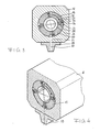
- FIGS. 2 and 4 Details of FIGS. 2 and 4 are shown in combination in FIG.
- the housing 12 is shown cut away in front, wherein the roller slide 13 from his is pulled out to the intended position to the front.
- In the intended Position would be a bore 36 for the nozzle 16 and the circumferential groove 25 lie with the radial bores 26 in a common axis normal plane.
Landscapes
- Coating Apparatus (AREA)
Abstract
Description
- einen inneren Hohlraum, dem flüssiges Medium zugeführt werden kann,
- eine Zylinderoberfläche
- erste Oberflächennuten in der Zylinderoberfläche, denen flüssiges Medium zugeführt werden kann und die drehstellungsabhängig mit der Schlitzdüse kommunizieren können,
- radiale Austrittsbohrungen vom inneren Hohlraum bis in die ersten Oberflächennuten, und
- zweite Oberflächennuten in der Zylinderoberfläche, die Verschlußleisten aufnehmen, die an der Oberfläche der Walzenkammer mit Vordruck anliegen, wobei jeder ersten Oberflächennut eine zweite Oberflächennut so zugeordnet ist, daß sie bei Drehung des Walzenschiebers der ersten Oberflächennut nacheilt.
- Figur 1
- zeigt einen Auftragskopf mit einer Materialbahn in perspektivischer Ansicht;
- Figur 2
- zeigt einen Walzenschieber mit achsparallelen ersten und zweiten Oberflächennuten als Einzelheit in perspektivischer Ansicht;
- Figur 3
- zeigt einen Auftragskopf mit Walzenschieber im Querschnitt;
- Figur 4
- zeigt einen quergeschnittenen Auftragskopf mit quergeschnittenem Walzenschieber in perspektivischer Ansicht;
- Figur 5
- zeigt einen Auftragskopf mit quergeschnittenem Gehäuse und vollständigem Walzenschieber.
- 11
- Auftragskopf
- 12
- Gehäuse
- 13
- Walzenschieber
- 14
- Pfeil
- 15
- Zapfen
- 16
- Radialstutzen
- 17
- Pfeil
- 18
- Schlitzdüse
- 19
- Sprühvorhang
- 20
- Walzenkammer
- 21
- Radialbohrung
- 22
- Materialbohrung
- 23
- Pfeil
- 24
- Auftragsraster
- 25
- Umfangsnut
- 26
- Radialbohrung
- 27
- Axialnut
- 28
- Radialbohrung
- 29
- Hohlraum
- 30
- Austrittsöffnung
- 31
- Axialnut
- 32
- Radialbohrung
- 33
- Verschlußleiste
- 34
- Schraubenfeder
- 35
- Zylinderoberfläche
- 36
- Bohrung
Claims (9)
- Auftragskopf (11) zum Auftragen von flüssigen Medien wie verflüssigten thermoplastischen Kunststoffen oder erschmolzenen Heißschmelzklebern auf eine zum Auftragskopf relativ bewegliche Materialbahn (22), mit einem Gehäuse (12), mit einer Walzenkammer (20) im Gehäuse, in der ein Walzenschieber (13) rotierend antreibbar gelagert ist, und mit einer Schlitzdüse (18) zum Ausbringen von flüssigem Medium, die vom Walzenschieber (13) steuerbar ist und sich quer zur Bewegungsrichtung der Materialbahn erstreckt,
wobei der Walzenschieber (13) folgende Merkmale aufweist:einen inneren Hohlraum (29), dem flüssiges Medium zugeführt werden kann,eine Zylinderoberflächeerste Oberflächennuten (27) in der Zylinderoberfläche, denen flüssiges Medium zugeführt werden kann und die drehstellungsabhängig mit der Schlitzdüse (18) kommunizieren können,radiale Austrittsbohrungen (28) vom inneren Hohlraum (29) bis in die ersten Oberflächennuten (27), undzweite Oberflächennuten (31) in der Zylinderoberfläche, die Verschlußleisten (32) aufnehmen, die an der Oberfläche der Walzenkammer (20) mit Vordruck anliegen, wobei jeder ersten Oberflächennut (27) eine zweite Oberflächennut (31) so zugeordnet ist, daß sie bei Drehung des Walzenschiebers (13) der ersten Oberflächennut nacheilt. - Auftragskopf nach Anspruch 1,
dadurch gekennzeichnet, daß die zweiten Oberflächennuten (31) und die einliegenden Verschlußleisten (32) im wesentlichen die gesamte Zylinderoberfläche (35) zwischen jeweils zwei ersten Oberflächennuten (27) einnehmen. - Auftragskopf nach Anspruch 1,
dadurch gekennzeichnet, daß die Oberflächennuten (27, 47, 67) als achsparallele Nuten ausgeführt sind. - Auftragskopf nach Anspruch 2,
gekennzeichnet durch
radiale Austrittsbohrungen (32) für flüssiges Medium vom inneren Hohlraum (29) bis in die zweiten Oberflächennuten (31). - Auftragskopf nach einem der Ansprüche 1 bis 4,
dadurch gekennzeichnet, daß an zumindest einem Ende des Gehäuses (12) ein Stutzen (16) im Gehäuse vorgesehen ist und ein Ringkanal zwischen Walzenschieber (13) und Walzenkammer (20) ausgebildet ist, der mit dem Stutzen im Gehäuse verbunden ist, und
daß radiale Zuführbohrungen (26) im Walzenschieber (13) in der Ebene des Ringkanals ausgeführt sind, die mit dem inneren Hohlraum (29) verbunden sind und dem Zuführen von flüssigem Medium dienen. - Auftragskopf nach einem der Ansprüche 1 bis 4,
dadurch gekennzeichnet, daß im Walzenschieber (13) zumindest an einem Ende eine Axialbohrung ausgeführt ist, die mit dem inneren Hohlraum (29) verbunden ist und dem Zuführen von flüssigem Medium dient, wobei die Axialbohrung insbesondere in einem axial aus dem Gehäuse austretenden Zapfen (15) ausgeführt ist. - Auftragskopf nach Anspruch 5,
dadurch gekennzeichnet, daß der zumindest eine Ringkanal durch eine Ringnut in der Walzenkammeroberfläche gebildet wird. - Auftragskopf nach Anspruch 5,
dadurch gekennzeichnet, daß der zumindest eine Ringkanal durch eine Umfangsnut (25) am Walzenschieber (13) gebildet wird. - Auftragskopf nach einem der Ansprüche 1 bis 8,
dadurch gekennzeichnet, daß in der Schlitzdüse (18) eine Blende mit einer Mehrzahl von Austrittsöffnungen für flüssiges Medium eingesetzt ist, wobei die Austrittsöffnungen (36) einzeln mit radialen Zuführbohrungen (21) im Gehäuse (11) von der Walzenkammer (20) aus verbunden sind.
Applications Claiming Priority (2)
| Application Number | Priority Date | Filing Date | Title |
|---|---|---|---|
| DE10216356A DE10216356C1 (de) | 2002-04-13 | 2002-04-13 | Rotationskopf mit Abstreifleisten |
| DE10216356 | 2002-04-13 |
Publications (3)
| Publication Number | Publication Date |
|---|---|
| EP1352691A2 true EP1352691A2 (de) | 2003-10-15 |
| EP1352691A3 EP1352691A3 (de) | 2006-06-07 |
| EP1352691B1 EP1352691B1 (de) | 2010-05-26 |
Family
ID=27762982
Family Applications (1)
| Application Number | Title | Priority Date | Filing Date |
|---|---|---|---|
| EP03007191A Expired - Lifetime EP1352691B1 (de) | 2002-04-13 | 2003-03-29 | Rotationskopf mit Verschlussleisten |
Country Status (4)
| Country | Link |
|---|---|
| US (1) | US6866209B2 (de) |
| EP (1) | EP1352691B1 (de) |
| DE (2) | DE10216356C1 (de) |
| ES (1) | ES2342051T3 (de) |
Families Citing this family (21)
| Publication number | Priority date | Publication date | Assignee | Title |
|---|---|---|---|---|
| US20030207206A1 (en) * | 2002-04-22 | 2003-11-06 | General Electric Company | Limited play data storage media and method for limiting access to data thereon |
| DE10320813B4 (de) * | 2003-05-08 | 2005-12-22 | Itw Dynatec Gmbh | Vorrichtung zum flächigen Auftragen von viskosen Medien |
| US7097710B2 (en) * | 2004-04-29 | 2006-08-29 | The Procter & Gamble Company | Extrusion applicator having rotational operability |
| DE102004030769A1 (de) * | 2004-06-25 | 2006-01-12 | Raumedic Ag | Mikrodosiersystem sowie Verfahren zum dosierten Benetzen eines Substrats |
| DE102004034422B4 (de) * | 2004-07-15 | 2006-12-28 | Nordson Corp., Westlake | Auftragskopf mit im Gehäuse federnd abgestütztem Düsenblock |
| DE102004058542A1 (de) * | 2004-12-03 | 2006-06-08 | Nordson Corporation, Westlake | Rotationsauftragskopf und Etikettieranlage zum Aufbringen von Etiketten |
| US7771556B2 (en) * | 2005-07-01 | 2010-08-10 | Nordson Corporation | Apparatus and process to apply adhesive during labeling operations |
| DE102008026147A1 (de) * | 2008-05-30 | 2009-12-03 | Fraunhofer-Gesellschaft zur Förderung der angewandten Forschung e.V. | Breitschlitzdüse |
| JP5786193B2 (ja) * | 2010-12-06 | 2015-09-30 | 兵神装備株式会社 | 吐出幅可変装置、及び塗布装置 |
| DE102011082631B4 (de) | 2011-09-13 | 2017-04-27 | VW-VM Forschungsgesellschaft mbH & Co. KG | Intermittierendes Beschichten von bewegten Oberflächen |
| US10632493B2 (en) * | 2015-09-29 | 2020-04-28 | Kimberly-Clark Worldwide, Inc. | Adhesive applicator with rotary valve |
| KR102338250B1 (ko) * | 2016-05-31 | 2021-12-10 | 쓰리엠 이노베이티브 프로퍼티즈 캄파니 | 캠 다이 코팅 시스템 |
| US20180030678A1 (en) * | 2016-08-01 | 2018-02-01 | Specialized Pavement Marking, Inc. | Striping apparatus |
| IT201700090917A1 (it) * | 2017-08-04 | 2019-02-04 | Tecno Italia S R L | Attrezzatura per la smaltatura di manufatti |
| ES3075908T3 (en) | 2018-12-14 | 2026-08-10 | System Ceram S P A | Equipment for the enameling of manufactured articles |
| CN110624769B (zh) * | 2019-09-11 | 2021-04-30 | 上海世禹精密机械有限公司 | 一种制造柔性电路板用的基材涂胶机 |
| CN113289836B (zh) * | 2021-05-25 | 2022-01-21 | 合壹(上海)展览有限公司 | 一种能够适用于不同形状板材的环保建材涂覆系统 |
| IT202200017310A1 (it) | 2022-08-12 | 2024-02-12 | Tecnocer Italia S R L | Apparecchiatura per la smaltatura di manufatti |
| IT202200021117A1 (it) | 2022-10-13 | 2024-04-13 | C I Me S Soc A Responsabilita Limitata | Macchina per l’applicazione di prodotti liquidi su un manufatto lastriforme |
| CN115489168B (zh) * | 2022-10-20 | 2023-08-08 | 温岭市森林包装有限公司 | 瓦楞纸板生产线 |
| IT202200025005A1 (it) * | 2022-12-05 | 2024-06-05 | C I Me S Soc A Responsabilita Limitata | Macchina per l’applicazione di prodotti liquidi su manufatti lastriformi |
Citations (1)
| Publication number | Priority date | Publication date | Assignee | Title |
|---|---|---|---|---|
| DE19757238C2 (de) | 1997-12-22 | 1999-11-25 | Wolfgang Puffe | Rotationsauftragskopf |
Family Cites Families (4)
| Publication number | Priority date | Publication date | Assignee | Title |
|---|---|---|---|---|
| US3332580A (en) * | 1965-09-20 | 1967-07-25 | Lockwood Tech | Fluid applicator valve |
| EP0286755B1 (de) * | 1987-04-16 | 1995-03-15 | Yasui Seiki Co., Ltd. | Speiseanordnung für eine Beschichtungsvorrichtung |
| US4968534A (en) * | 1989-01-17 | 1990-11-06 | Npd Corp. | Method and apparatus for pattern impregnation of a porous web |
| US5360516A (en) * | 1992-11-12 | 1994-11-01 | Philip Morris Incorporated | Application of fluidized material to a substrate using intermittent charges of compressed air |
-
2002
- 2002-04-13 DE DE10216356A patent/DE10216356C1/de not_active Expired - Fee Related
-
2003
- 2003-03-29 ES ES03007191T patent/ES2342051T3/es not_active Expired - Lifetime
- 2003-03-29 DE DE50312733T patent/DE50312733D1/de not_active Expired - Lifetime
- 2003-03-29 EP EP03007191A patent/EP1352691B1/de not_active Expired - Lifetime
- 2003-04-11 US US10/412,159 patent/US6866209B2/en not_active Expired - Lifetime
Patent Citations (1)
| Publication number | Priority date | Publication date | Assignee | Title |
|---|---|---|---|---|
| DE19757238C2 (de) | 1997-12-22 | 1999-11-25 | Wolfgang Puffe | Rotationsauftragskopf |
Also Published As
| Publication number | Publication date |
|---|---|
| ES2342051T3 (es) | 2010-07-01 |
| US20030230647A1 (en) | 2003-12-18 |
| EP1352691A3 (de) | 2006-06-07 |
| DE50312733D1 (de) | 2010-07-08 |
| US6866209B2 (en) | 2005-03-15 |
| DE10216356C1 (de) | 2003-09-18 |
| EP1352691B1 (de) | 2010-05-26 |
Similar Documents
| Publication | Publication Date | Title |
|---|---|---|
| EP1352691B1 (de) | Rotationskopf mit Verschlussleisten | |
| EP0850697B1 (de) | Vorrichtung zum Auftragen von fliessfähigem Material auf ein Substrat, insbesondere zum intermittierenden Auftragen von flüssigem Klebstoff | |
| EP1042074B1 (de) | Rotationsauftragskopf | |
| DE2100771C3 (de) | Gerät zum Auftragen von Fluiden | |
| EP1658902B1 (de) | Steuermodul für eine Düsenanordnung | |
| EP2468413A2 (de) | Vorrichtung und Verfahren zum Beschichten eines Gegenstandes mit einem Medium | |
| DE102004058542A1 (de) | Rotationsauftragskopf und Etikettieranlage zum Aufbringen von Etiketten | |
| DE69301182T2 (de) | Durch eine Magnetspule betätigte Flüssigkeitssprühpistole | |
| EP1344573B1 (de) | Rotationsauftragskopf | |
| DE69208402T2 (de) | Schlitzdüse zum Medienauftrag | |
| EP0747132B1 (de) | Vorrichtung zum Auftragen pastöser Medien | |
| DE10057733A1 (de) | Vorhang-Auftragsvorrichtung | |
| EP2282846B1 (de) | Breitschlitzdüse | |
| DE10023673B4 (de) | Verteilervorrichtung zum Verteilen von Fluiden sowie Vorrichtung zum Abgeben und Auftragen von Fluid, insbesondere Klebstoff | |
| DE10306884B3 (de) | Auftragskopf mit Drehschieberverschluss | |
| DE102004034422B4 (de) | Auftragskopf mit im Gehäuse federnd abgestütztem Düsenblock | |
| DE102010025119B4 (de) | Beschichtungsdüse | |
| DE2737993A1 (de) | Vorrichtung zum ausgeben von klebstoff | |
| DE10320856B3 (de) | Mehrfach-Düsenkopf | |
| DE19824538C2 (de) | Verfahren und Vorrichtung zum Auftragen von flüssigen Medien | |
| EP1623769B1 (de) | Auftragskopf | |
| WO1990000471A1 (de) | Verfahren und vorrichtung zum herstellen von klebenähten quer zur bewegungsrichtung einer bahn | |
| DE102014116607B4 (de) | Kartusche zum dosierten Ausbringen von flüssigen Medien und deren Verwendung | |
| DE102014116585B4 (de) | Spritzvorrichtung und System mit einer Spritzvorrichtung und einer Kartusche | |
| EP1082177B1 (de) | Verfahren und vorrichtung zum auftragen von flüssigen medien |
Legal Events
| Date | Code | Title | Description |
|---|---|---|---|
| PUAI | Public reference made under article 153(3) epc to a published international application that has entered the european phase |
Free format text: ORIGINAL CODE: 0009012 |
|
| AK | Designated contracting states |
Kind code of ref document: A2 Designated state(s): AT BE BG CH CY CZ DE DK EE ES FI FR GB GR HU IE IT LI LU MC NL PT RO SE SI SK TR |
|
| AX | Request for extension of the european patent |
Extension state: AL LT LV MK |
|
| RAP1 | Party data changed (applicant data changed or rights of an application transferred) |
Owner name: NORDSON CORPORATION |
|
| RIN1 | Information on inventor provided before grant (corrected) |
Inventor name: PUFFE, WOLFGANG |
|
| PUAL | Search report despatched |
Free format text: ORIGINAL CODE: 0009013 |
|
| AK | Designated contracting states |
Kind code of ref document: A3 Designated state(s): AT BE BG CH CY CZ DE DK EE ES FI FR GB GR HU IE IT LI LU MC NL PT RO SE SI SK TR |
|
| AX | Request for extension of the european patent |
Extension state: AL LT LV MK |
|
| 17P | Request for examination filed |
Effective date: 20061106 |
|
| AKX | Designation fees paid |
Designated state(s): DE ES IT |
|
| 17Q | First examination report despatched |
Effective date: 20070131 |
|
| GRAP | Despatch of communication of intention to grant a patent |
Free format text: ORIGINAL CODE: EPIDOSNIGR1 |
|
| GRAS | Grant fee paid |
Free format text: ORIGINAL CODE: EPIDOSNIGR3 |
|
| GRAA | (expected) grant |
Free format text: ORIGINAL CODE: 0009210 |
|
| AK | Designated contracting states |
Kind code of ref document: B1 Designated state(s): DE ES IT |
|
| REG | Reference to a national code |
Ref country code: ES Ref legal event code: FG2A Ref document number: 2342051 Country of ref document: ES Kind code of ref document: T3 |
|
| REF | Corresponds to: |
Ref document number: 50312733 Country of ref document: DE Date of ref document: 20100708 Kind code of ref document: P |
|
| PLBE | No opposition filed within time limit |
Free format text: ORIGINAL CODE: 0009261 |
|
| STAA | Information on the status of an ep patent application or granted ep patent |
Free format text: STATUS: NO OPPOSITION FILED WITHIN TIME LIMIT |
|
| 26N | No opposition filed |
Effective date: 20110301 |
|
| REG | Reference to a national code |
Ref country code: DE Ref legal event code: R097 Ref document number: 50312733 Country of ref document: DE Effective date: 20110228 |
|
| PGFP | Annual fee paid to national office [announced via postgrant information from national office to epo] |
Ref country code: DE Payment date: 20180322 Year of fee payment: 16 |
|
| PGFP | Annual fee paid to national office [announced via postgrant information from national office to epo] |
Ref country code: ES Payment date: 20180427 Year of fee payment: 16 |
|
| PGFP | Annual fee paid to national office [announced via postgrant information from national office to epo] |
Ref country code: IT Payment date: 20180327 Year of fee payment: 16 |
|
| REG | Reference to a national code |
Ref country code: DE Ref legal event code: R119 Ref document number: 50312733 Country of ref document: DE |
|
| PG25 | Lapsed in a contracting state [announced via postgrant information from national office to epo] |
Ref country code: DE Free format text: LAPSE BECAUSE OF NON-PAYMENT OF DUE FEES Effective date: 20191001 |
|
| PG25 | Lapsed in a contracting state [announced via postgrant information from national office to epo] |
Ref country code: IT Free format text: LAPSE BECAUSE OF NON-PAYMENT OF DUE FEES Effective date: 20190329 |
|
| REG | Reference to a national code |
Ref country code: ES Ref legal event code: FD2A Effective date: 20200728 |
|
| PG25 | Lapsed in a contracting state [announced via postgrant information from national office to epo] |
Ref country code: ES Free format text: LAPSE BECAUSE OF NON-PAYMENT OF DUE FEES Effective date: 20190330 |