EP2282846B1 - Breitschlitzdüse - Google Patents
Breitschlitzdüse Download PDFInfo
- Publication number
- EP2282846B1 EP2282846B1 EP09753950.6A EP09753950A EP2282846B1 EP 2282846 B1 EP2282846 B1 EP 2282846B1 EP 09753950 A EP09753950 A EP 09753950A EP 2282846 B1 EP2282846 B1 EP 2282846B1
- Authority
- EP
- European Patent Office
- Prior art keywords
- tube
- medium
- slot
- discharge nozzle
- housing
- Prior art date
- Legal status (The legal status is an assumption and is not a legal conclusion. Google has not performed a legal analysis and makes no representation as to the accuracy of the status listed.)
- Active
Links
- 238000007789 sealing Methods 0.000 claims description 60
- 230000009969 flowable effect Effects 0.000 claims description 6
- 230000004323 axial length Effects 0.000 claims description 3
- 230000015572 biosynthetic process Effects 0.000 claims 1
- NJPPVKZQTLUDBO-UHFFFAOYSA-N novaluron Chemical compound C1=C(Cl)C(OC(F)(F)C(OC(F)(F)F)F)=CC=C1NC(=O)NC(=O)C1=C(F)C=CC=C1F NJPPVKZQTLUDBO-UHFFFAOYSA-N 0.000 claims 1
- 239000000853 adhesive Substances 0.000 description 4
- 230000001070 adhesive effect Effects 0.000 description 4
- 239000000463 material Substances 0.000 description 4
- 230000008878 coupling Effects 0.000 description 3
- 238000010168 coupling process Methods 0.000 description 3
- 238000005859 coupling reaction Methods 0.000 description 3
- 239000011324 bead Substances 0.000 description 2
- 238000011161 development Methods 0.000 description 2
- 230000018109 developmental process Effects 0.000 description 2
- 239000007788 liquid Substances 0.000 description 2
- 238000003825 pressing Methods 0.000 description 2
- 239000004831 Hot glue Substances 0.000 description 1
- 230000009286 beneficial effect Effects 0.000 description 1
- 238000000576 coating method Methods 0.000 description 1
- 230000000295 complement effect Effects 0.000 description 1
- 238000005520 cutting process Methods 0.000 description 1
- 230000001419 dependent effect Effects 0.000 description 1
- 230000000694 effects Effects 0.000 description 1
- 238000004519 manufacturing process Methods 0.000 description 1
- 230000013011 mating Effects 0.000 description 1
- 239000003973 paint Substances 0.000 description 1
- 230000002093 peripheral effect Effects 0.000 description 1
- 230000000087 stabilizing effect Effects 0.000 description 1
- 238000003860 storage Methods 0.000 description 1
- 229920001169 thermoplastic Polymers 0.000 description 1
- 239000004416 thermosoftening plastic Substances 0.000 description 1
Images


Classifications
-
- B—PERFORMING OPERATIONS; TRANSPORTING
- B05—SPRAYING OR ATOMISING IN GENERAL; APPLYING FLUENT MATERIALS TO SURFACES, IN GENERAL
- B05C—APPARATUS FOR APPLYING FLUENT MATERIALS TO SURFACES, IN GENERAL
- B05C5/00—Apparatus in which liquid or other fluent material is projected, poured or allowed to flow on to the surface of the work
- B05C5/02—Apparatus in which liquid or other fluent material is projected, poured or allowed to flow on to the surface of the work the liquid or other fluent material being discharged through an outlet orifice by pressure, e.g. from an outlet device in contact or almost in contact, with the work
- B05C5/0254—Coating heads with slot-shaped outlet
- B05C5/0258—Coating heads with slot-shaped outlet flow controlled, e.g. by a valve
-
- B—PERFORMING OPERATIONS; TRANSPORTING
- B05—SPRAYING OR ATOMISING IN GENERAL; APPLYING FLUENT MATERIALS TO SURFACES, IN GENERAL
- B05C—APPARATUS FOR APPLYING FLUENT MATERIALS TO SURFACES, IN GENERAL
- B05C5/00—Apparatus in which liquid or other fluent material is projected, poured or allowed to flow on to the surface of the work
- B05C5/02—Apparatus in which liquid or other fluent material is projected, poured or allowed to flow on to the surface of the work the liquid or other fluent material being discharged through an outlet orifice by pressure, e.g. from an outlet device in contact or almost in contact, with the work
- B05C5/0225—Apparatus in which liquid or other fluent material is projected, poured or allowed to flow on to the surface of the work the liquid or other fluent material being discharged through an outlet orifice by pressure, e.g. from an outlet device in contact or almost in contact, with the work characterised by flow controlling means, e.g. valves, located proximate the outlet
- B05C5/0229—Apparatus in which liquid or other fluent material is projected, poured or allowed to flow on to the surface of the work the liquid or other fluent material being discharged through an outlet orifice by pressure, e.g. from an outlet device in contact or almost in contact, with the work characterised by flow controlling means, e.g. valves, located proximate the outlet the valve being a gate valve or a sliding valve
- B05C5/0233—Apparatus in which liquid or other fluent material is projected, poured or allowed to flow on to the surface of the work the liquid or other fluent material being discharged through an outlet orifice by pressure, e.g. from an outlet device in contact or almost in contact, with the work characterised by flow controlling means, e.g. valves, located proximate the outlet the valve being a gate valve or a sliding valve rotating valve, e.g. rotating perforated cylinder
Definitions
- the invention relates to a device according to the preamble of claim 1.
- Such a device describes the US 2006/01639 A1 ,
- the device has a housing with an elongate outlet nozzle. Within the housing there is a designed as a cylindrical tube medium distributor.
- the tube has on its lateral surface a circumferentially extending slot which passes at a rotation of the tube at the outlet nozzle.
- the device is able to apply an adhesive bead on a surface, wherein the course of the adhesive bead corresponds to the slot profile of the medium distributor.
- the GB 1 169 973 A describes a device for the surface delivery of an adhesive in which an inner tube is inserted in an outer tube. Both tubes have superimposed outlet slots.
- the DE 10216 356 C1 describes a device for dispensing a liquid medium, in which a rotational body is rotatably mounted within a housing.
- the housing and the rotary body have slots.
- the DE 103 06 884 B3 discloses an applicator head for applying liquid media with a rotary valve closure.
- a device in which a tubular medium distributor is mounted in a two-part housing with a slot extending in the axial direction of the tube.
- the tube having a circular cross-section is rotatably mounted in a congruent inner cylinder.
- the two housing parts each form two halves of the inner cylinder, wherein a lower housing part has an outlet slot which is flanked by two outlet lips.
- the lower housing part has a along in the region of the inner cylinder the edge of the exit slot extending recess with a wedge-shaped tapered bottom.
- the DE 197 57 237 C2 describes a device in which a longitudinal slot is in a substantially rectangular housing, which forms an over almost the entire length of the housing extending outlet nozzle.
- a roller with a helical groove extending on the roller surface slot.
- a flowable medium which may be a liquefied thermoplastic or a molten hot melt adhesive.
- the roll surface lies in sealing engagement with a bottom surface of the housing in which the outlet nozzle formed by a longitudinal slot is located.
- the helical slot of the medium distributor thus crosses the outlet nozzle at a plurality of spaced-apart locations. At these intersections, the flowable medium can escape from the outlet nozzle. If the medium distributor is rotated, this exit point migrates further in the nozzle extension direction. With the rotary application head described there, separate adhesive threads can be applied to a flat workpiece surface.
- the invention has the object of developing a generic device such that low to medium-viscosity media closed area on a flat workpiece surface can be applied, the mass flow of the medium is precisely on and off.
- the counter-sealing surfaces do not come from the housing, but from one in a recess of the housing Sealing strip are formed with a slot aligned with the outlet nozzle.
- a high sealing effect can be achieved, in particular by targeted application of a local pressure, so that the mass flow can be precisely switched on and off.
- the interior of the tube forms a reservoir which can be fed with a medium from a feed opening.
- the tube has a slot. This runs in such a way that it can be brought from an open position into a closed position by rotating the tube. In the open position, a passage opening which is open essentially over the entire length of the outlet opening forms from the reservoir to the outlet nozzle. In the closed position, this passage opening is completely closed.
- the housing is preferably formed by a half-tube.
- This half pipe runs centrally the outlet nozzle.
- the half tube forms a shell which receives the medium distributor.
- the half pipe also forms the arranged in the region of the outlet nozzle sealing strip.
- the material thickness of the sealing strip is preferably greater than the depth of the recess, so that the sealing strip protrudes like a socket from the recess.
- the inner wall of the housing thus has a distance from the outer wall of the medium distributor.
- the width of the sealing strip is limited to the immediate apex area of the tube.
- the sealing surfaces formed by the sealing strip run on a cylinder inner surface.
- the sealing strip forms sealing surfaces adapted to the outer wall of the pipe forming the medium distributor.
- the medium distributor against these sealing surfaces of the medium distributor is pressed with An horriliax, so that in the closed position no medium can escape from the reservoir. If the medium distributor is rotated into the open position, the medium can flow through the slot of the tube and the slot of the sealing strip into the slot forming the outlet nozzle in order to emerge uniformly from the outlet nozzle.
- To increase the stability of the slot of the sealing strip may be interrupted by a plurality of webs. The webs are spaced apart, wherein the distance between the webs corresponds to at least ten times the slot width. Measured in the extension direction of the outlet nozzle Length of the webs corresponds approximately to the slot width.
- the medium distributor has a substantially circular cross-sectional contour.
- the feed opening lies in the center of rotation of the medium distributor.
- the two ends of the half-tube are connected to headers, which slide the bearing plugs.
- the half tube may consist of two quarter tubes, which are connected to each other by means of the two head pieces but also with the help of the sealing strip and in particular glued.
- the pipe forming the medium distributor can be axially slotted over the entire length.
- the front ends of the tube can be glued to the bearing plug.
- the slot die according to the invention allows the application of low to medium-viscosity media and consists essentially of a slotted tube, which simultaneously forms a material reservoir. This tube has one or two side ports for media supply.
- the outlet nozzle forms the mating contour to the slot of the roller.
- the sealing strip has two mutually spaced by a slot sealing surfaces, which abut sealingly adjacent to the slot outer wall sections of the tube.
- the sealing strip thus lies between the slotted roller and the outlet nozzle.
- the material reservoir is dimensioned so that a uniform pressure prevails in the slotted hollow cylinder, preferably of the order of magnitude of 0.5 to 6 bar. This ensures that even with larger application widths, in particular from 500 mm to 1000 mm, uniform media application takes place.
- the connection of the reservoir is released to the outlet nozzle. This enables both a defined start of application and a defined end of application.
- structured coatings can be applied to surfaces of workpieces.
- the device With the device also vertical surfaces can be coated. It is even possible to work overhead with the nozzle. For this purpose, prove the radially projecting, the outlet nozzle flanking lips as beneficial.
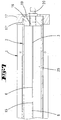
- a housing 1 provided in the form of a half-pipe.
- This shell-like housing 1 forms the nozzle carrier.
- the shell which extends approximately over a semicircle, has in its center a longitudinal slot which forms an outlet nozzle 4.
- the longitudinal slot extends over the entire length of the half pipe 1, so that the half pipe 1 is composed of two quarter pipe sections.
- the two front ends of the half tube 1 are connected to head pieces 24 and 17, respectively.
- the head pieces 17,24 form essentially cylindrical bodies and a bearing recess 17 ', 24'.
- the inner wall of the half tube 1 has a recess 7 having the shape of a rectangular groove.
- this recess 7 there is a sealing strip 3.
- the sealing strip 3 extends essentially over the entire length of the half tube 1 and has a longitudinally extending, central slot.
- the slot 5 is aligned with the outlet nozzle 4.
- the material thickness the sealing strip 3 is larger than the depth of the recess 7, so that the counter portion 3 'forming head portion of the sealing strip 3 protrudes like a socket over the inner wall of the housing 1.
- the slot 6 of the sealing strip 3 has interruptions in the form of spaced webs 15.
- the slot 6 does not extend to the respective ends of the sealing strip 3, so that this Sections have a stabilizing effect.
- the sealing strip 3 can be glued into the recess 7. It forms a slot 5 flanking sealing surface 3 ', which is curved arcuately inwardly in cross section, wherein the arc shape of the sealing surface 3' of the outer contour of a tube 2 is adjusted.
- the sealing surface 2 'of the tube 2 and the sealing surface 3' of the sealing strip 3 extends only over a achtel Vietnamese.
- the angle ⁇ over which the sealing surface extends may preferably be in a range of 30 to 60 °.
- the support of the tube 2 in the region of the slot 5 thus extends only over a limited peripheral region, which is formed by the curved surface 3 'of the socket-like inner wall 26 of the housing 1 superior sealing strip 3.
- an arcuate space 28 is formed between the outer wall 27 of the tube 2 and extending on an inner cylindrical surface inner wall 26 of the housing 1.
- the tube 2 forms a medium distributor and is mounted in the cavity of the half-tube.
- the tube 2 has a over the entire length of the tube 2 extending longitudinal slot 6.
- the longitudinal slot 6 is flanked by sealing surfaces 2 ', which rest in sealing contact with the counter-sealing surfaces 3' of the sealing strip 3.
- the sealing strip 3 extends with its running on an inner cylindrical surface counter-sealing surfaces 3 'only via Thus, only small radial forces are required in order to achieve a sufficiently high surface pressure in the region of the contact surfaces (sealing surfaces 2 ', 3').
- the tube 2 is closed at its front ends with bearing plugs 16, 21.
- the bearing plugs 16, 21 may be glued to the tube 2.
- the bearing plug 21 forms a central projection 22 which is mounted with the interposition of a bearing ring in the bearing recess 24 'of the head piece 24.
- a portion of the bearing extension 22 is frontally over. Thereof a shift lever 14 is attached.
- the bearing plug 16 is mounted with the interposition of a bearing ring in the bearing recess 17 'of the head piece 17.
- the bearing plug 16 forms a central opening 19, in which a coupling piece 20 is screwed.
- the coupling piece 20 can be connected to a supply hose or supply pipe, so that through the feed opening 19, the interior 25 of the tube 2 can be filled with a flowable medium.
- the interior of the tube 2 thus forms a reservoir 25.
- each Anyak Gland 9 forms two each about a bearing axis 12 rotatable pressure rollers 10.
- the two ends of the An für Seae 9 are connected by means of clamping screws 13 with the two edges of the half tube. They complement the cross section of the half tube 1 to a full tube, wherein by means of the tensioning screws 13 can be applied and adjustable clamping force the pressure rollers 10 are brought into exciting contact with the outer wall of the tube 2.
- the a pressing piece 9 forming elbow has an inner wall facing the tube 2, which is spaced from the outer wall 27 of the tube 2.
- the pressure rollers 10 have portions that protrude into this space spacing.
- the pressure rollers 10 are offset laterally to a running through the radial slot 4 diametrical, so that the bearing axes 12 and the outlet nozzle form 4 points of an isosceles triangle.
- the pressing pieces 9 which are substantially uniformly spaced from one another in the axial direction, a force can be exerted on the tube 2 in the radial direction, which force is discharged into the superposed sealing surfaces 2 ', 3'.
- the clamping screws 13 the force can be adjusted locally, so that manufacturing tolerances in the course of the sealing surfaces 2 ', 3' can be compensated locally. If it comes to longer leaks to local leaks, they can be fixed by tightening the clamping screws 13 of the local An horraus 9.
- the operation of the device is the following:
- the reservoir 25 is fed with a flowable, in particular low to medium viscosity medium.
- this medium it is preferably a textured paint to be applied to a flat surface of a workpiece.
- the slot die is installed in a device, not shown, so that it can be displaced with respect to the workpiece or the workpiece relative to the slot die at a uniform speed.
- the medium can escape from the outlet nozzle 4. It enters first through the slot 6 in the only slightly interrupted, aligned flush slot 5 of the sealing strip 3 and from there into the likewise aligned longitudinal slot of the outlet nozzle 4.
- the opening of the outlet nozzle 4 is flanked by extending in the radial direction of lips 8, which are formed by mutually parallel cutouts.
- the application of the medium takes place either from top to bottom on horizontal surfaces or sideways in the vertical direction on vertical surfaces. But it is also possible to work with the slot die overhead, so that horizontal surfaces can be coated from below.
Description
- Die Erfindung betrifft eine Vorrichtung gemäß Gattungsbegriff des Anspruches 1.
- Eine derartige Vorrichtung beschreibt die
US 2006/01639 A1 . Die Vorrichtung besitzt ein Gehäuse mit einer langgestreckten Austrittsdüse. Innerhalb des Gehäuses befindet sich ein als zylindrisches Rohr gestalteter Mediumverteiler. Das Rohr besitzt auf seiner Mantelfläche ein sich in Umfangsrichtung erstreckenden Schlitz, der bei einer Drehung des Rohres an der Austrittsdüse vorbeiläuft. Die Vorrichtung ist in der Lage, einen Klebewulst auf eine Oberfläche aufzubringen, wobei der Verlauf des Klebewulstes dem Schlitzverlauf des Mediumverteilers entspricht. - Die
GB 1 169 973 A - Die
DE 10216 356 C1 beschreibt eine Vorrichtung zur Abgabe eines flüssigen Mediums, bei der innerhalb eines Gehäuses ein Rotationskörper drehbar gelagert ist. Das Gehäuse und der Rotationskörper besitzen Schlitze. - Die
DE 103 06 884 B3 offenbart einen Auftragskopf zum Aufbringen flüssiger Medien mit einem Drehschieberverschluss. - Aus der
DE 33 22154 ist eine Vorrichtung bekannt, bei der in einem zweiteiligen Gehäuse ein rohrförmiger Mediumverteiler mit einem in Axialrichtung des Rohres verlaufenden Schlitz lagert. Das einen kreisförmigen Querschnitt aufweisende Rohr ist in einem dazu kongruenten Innenzylinder drehbar gelagert. Die beiden Gehäuseteile bilden jeweils zwei Hälften des Innenzylinders, wobei ein unteres Gehäuseteil einen Austrittsschlitz aufweist, der von zwei Austrittslippen flankiert ist. Das untere Gehäuseteil besitzt im Bereich des Innenzylinders eine sich entlang des Randes des Austrittsschlitzes erstreckende Ausnehmung mit einem keilförmig sich verjüngenden Boden. Durch Drehen des Mediumverteilers gelangt der schlitzförmige Auslass in den Bereich dieser Ausnehmung. Der Abstand des Bodens dieser Ausnehmung hängt von der Drehstellung des Rohres ab. Die Ausnehmung bildet eine Drossel, so dass durch die Variation der Drehstellung des Rohres die Durchflussmenge durch den Spalt eingestellt werden kann. - Die
DE 197 57 237 C2 beschreibt eine Vorrichtung, bei der in einem im Wesentlichen rechteckigen Gehäuse sich ein Längsschlitz befindet, der eine sich über im Wesentlichen die gesamte Länge des Gehäuses erstreckende Austrittsdüse ausbildet. Innerhalb des Gehäuses befindet sich eine Walze mit einem wendelgangförmig auf der Walzenoberfläche verlaufenden Schlitz. Zwischen der Außenwandung der Walze und der Innenwandung des Gehäuses befindet sich ein Reservoir zur Aufnahme eines fließfähigen Mediums, bei dem es sich um einen verflüssigten thermoplastischen Kunststoff oder einen erschmolzenen Heizschmelzkleber handeln kann. Die Walzenoberfläche liegt in dichtender Anlage an einer Bodenfläche des Gehäuses, in welcher sich die von einem Längsschlitz gebildete Austrittsdüse befindet. Der wendelgangförmige Schlitz des Mediumverteilers kreuzt somit an mehreren voneinander beabstandeten Stellen die Austrittsdüse. An diesen Kreuzungsstellen kann das fließfähige Medium aus der Austrittsdüse austreten. Wird der Mediumverteiler gedreht, so wandert diese Austrittsstelle in Düsenerstreckungsrichtung weiter. Mit dem dort beschriebenen Rotationsauftragskopf können voneinander getrennte Klebefäden auf eine ebene Werkstückoberfläche aufgebracht werden. - Der Erfindung liegt die Aufgabe zugrunde, eine gattungsgemäße Vorrichtung derart weiterzubilden, dass niedrig- bis mittelsviskose Medien geschlossenflächig auf eine ebene Werkstückoberfläche aufbringbar sind, wobei der Massenstrom des Mediums präzise ein- und ausschaltbar ist.
- Gelöst wird die Aufgabe durch die im Anspruch 1 angegebene Erfindung. Die Unteransprüche stellen vorteilhafte Weiterbildungen dar.
- Zunächst und im Wesentlichen ist vorgesehen, dass die Gegendichtflächen nicht vom Gehäuse, sondern von einer in einer Aussparung des Gehäuses einliegenden Dichtleiste mit einem zur Austrittsdüse fluchtenden Schlitz gebildet sind. Zufolge dieser Ausgestaltung lässt sich insbesondere durch gezielte Aufbringung eines lokalen Drucks eine hohe Dichtwirkung erreichen, so dass der Massenfluss präzise ein- und ausgeschaltet werden kann. Das Innere des Rohres bildet eine von einer Speiseöffnung mit einem Medium speisbares Reservoir aus. Das Rohr besitzt einen Schlitz. Dieser verläuft derart, dass er durch Drehen des Rohres von einer Offenstellung in eine Geschlossenstellung bringbar ist. In der Offenstellung bildet sich eine im Wesentlichen über die gesamte Länge der Austrittsöffnung offene Durchtrittsöffnung vom Reservoir zur Austrittsdüse aus. In der Geschlossenstellung ist diese Durchtrittsöffnung vollständig verschlossen. Das Gehäuse wird bevorzugt von einem Halbröhr ausgebildet. In diesem Halbrohr verläuft mittig die Austrittsdüse. Das Halbrohr bildet eine Schale, die den Mediumverteiler aufnimmt. Das Halbrohr bildet darüber hinaus die im Bereich der Austrittsdüse angeordnete Dichtleiste. Die Materialstärke der Dichtleiste ist bevorzugt größer, als die Tiefe der Aussparung, so dass die Dichtleiste sockelartig aus der Aussparung herausragt. Die Innenwandung des Gehäuses besitzt somit einen Abstand zur Außenwandung des Mediumverteilers. Die Breite der Dichtleiste beschränkt sich auf den unmittelbaren Scheitelbereich des Rohres. Die von der Dichtleiste ausgebildeten Dichtflächen verlaufen auf einer Zylinderinnenfläche. Die Dichtleiste bildet an die Außenwandung des den Mediumverteiler ausbildenden Rohres angepasste Dichtflächen. Gegen diese Dichtflächen wird der Mediumverteiler mit Andruckstücken angepresst, so dass in der Geschlossenstellung kein Medium aus dem Reservoir austreten kann. Wird der Mediumverteiler in die Offenstellung gedreht, so kann das Medium durch den Schlitz des Rohres und den Schlitz der Dichtleiste in den die Austrittsdüse ausbildenden Schlitz strömen, um gleichmäßig aus der Austrittsdüse auszutreten. Zur Erhöhung der Stabilität kann der Schlitz der Dichtleiste von mehreren Stegen unterbrochen sein. Die Stege sind voneinander beabstandet, wobei der Abstand zwischen den Stegen mindestens dem Zehnfachen der Schlitzweite entspricht. Die in Erstreckungsrichtung der Austrittsdüse gemessene Länge der Stege entspricht in etwa der Schlitzweite. Der Mediumverteiler besitzt eine im Wesentlichen kreisrunde Querschnittsumrisskontur. Gegen die auf dieser Umrisskontur verlaufenden Mantelfläche drücken Druckrollen der Andruckstücke. Die Andruckstücke sind voneinander beabstandet und haben eine bogenförmige Gestalt. Die Enden der Bogenstücke sind mit den Rändern des Halbrohres mit Einstellschrauben verschraubt. Im Querschnitt liegen die Druckrollen der Austrittsdüse gegenüber, wobei sich ein spitzwinkliges gleichschenkliges Dreieck ausbildet. Die Kraft, mit der die Andruckstücke die Dichtflächen des Rohres gegen die Dichtflächen der Dichtleiste beaufschlagen, kann mittels der Einstellschrauben lokal eingestellt werden. Das den Mediumverteiler ausbildende Rohr ist an seinen Stirnseiten mit Lagerstopfen verschlossen. Einer der beiden Lagerstopfen bildet einen Fortsatz, der mit einem Schalthebel verbunden ist, mit dem der Mediumverteiler gedreht werden kann. Der diesem Lagerstopfen gegenüberliegende Lagerstopfen bildet die Speiseöffnung aus. Die Speiseöffnung liegt dabei im Drehzentrum des Mediumverteilers. Die beiden Enden des Halbrohres sind mit Kopfstücken verbunden, die die Lagerstopfen gleitlagern. Das Halbrohr kann aus zwei Viertelrohren bestehen, die mit Hilfe der beiden Kopfstücke aber auch mit Hilfe der Dichtleiste miteinander verbunden und insbesondere verklebt sind. Das den Mediumverteiler ausbildende Rohr kann über die gesamte Länge axialgeschlitzt sein. Die Stirnenden des Rohres können mit den Lagerstopfen verklebt sein. Die erfindungsgemäße Breitschlitzdüse ermöglicht die Applikation niedrig- bis mittelviskoser Medien und besteht im Wesentlichen aus einem geschlitzten Rohr, welches gleichzeitig ein Materialreservoir ausbildet. Dieses Rohr besitzt ein oder zwei seitliche Anschlüsse zur Medienzuführung. Die Austrittsdüse bildet die Gegenkontur zum Schlitz der Walze. Die Dichtleiste besitzt zwei voneinander durch einen Schlitz beabstandete Dichtflächen, an denen dichtend dem Schlitz benachbarte Außenwandungsabschnitte des Rohres anliegen. Die Dichtleiste liegt somit zwischen der geschlitzten Walze und der Austrittsdüse. Mit den Andruckstücken kann die den Mediumverteiler bildende geschlitzte Walze örtlich gezielt an die Flanken der Austrittsdüse angedrückt werden. Das Materialreservoir ist so dimensioniert, dass in der geschlitzten Hohlwalze ein gleichmäßiger Druck herrscht, vorzugsweise in der Größenordnung von 0,5 bis 6 Bar. Dadurch wird erreicht, dass auch bei größeren Auftragsbreiten, insbesondere von 500 mm bis 1000 mm ein gleichmäßiger Medienauftrag erfolgt. Durch Verdrehen der geschlitzten Walze, insbesondere über den Schalthebel, wird die Verbindung des Reservoirs zur Austrittsdüse freigegeben. Damit ist sowohl ein definierter Applikationsbeginn als auch ein definiertes Applikationsende möglich. Mit der erfindungsgemäßen Breitschlitzdüse können Strukturlacke auf Oberflächen von Werkstücken aufgebracht werden. Mit der Vorrichtung können auch senkrecht stehende Flächen beschichtet werden. Es ist sogar möglich, mit der Düse über Kopf zu arbeiten. Hierzu erweisen sich die radial abragenden, die Austrittsdüse flankierenden Lippen als vorteilhaft.
- Ein Ausführungsbeispiel der Erfindung wird nachfolgend anhand beigefügter Zeichnungen erläutert. Es zeigen:
- Fig. 1
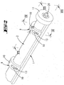
- in einer ersten perspektivischen Darstellung eine Breitschlitzdüse,
- Fig. 2
- eine vergrößerte Darstellung des in
Fig. 1 rechts dargestellten Endes, - Fig. 3
- eine vergrößerte Darstellung des in der
Fig. 1 links dargestellten Endes in Blickrichtung des Pfeils III inFig. 1 , - Fig. 4
- einen Schnitt gemäß der Linie IV-IV in
Fig. 2 , - Fig. 5
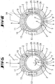
- den Schnitt gemäß
Fig. 4 mit Blick auf die Schnittebene in der Öffnungsstellung, - Fig. 6
- eine Darstellung gemäß
Fig. 5 in der Geschlossenstellung, - Fig. 7
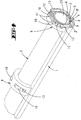
- einen Schnitt gemäß der Linie VII-VII in
Fig. 2 , - Fig. 8
- einen Schnitt gemäß der Linie VIII-VIII in
Fig. 3 , - Fig. 9
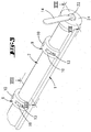
- eine weitere perspektivische Darstellung der Breitschlitzdüse,
- Fig. 10
- eine Explosionsdarstellung der einzelnen Elemente der Breitschlitzdüse und
- Fig. 11
- einen Ausschnitt gemäß Linie XI in
Fig. 10 . - Bei der in den
Figuren 1 bzw. 9 in der Totalen dargestellten Breitschlitzdüse handelt es sich um einen langgestreckten, im Wesentlichen zylindrischen Körper von einer Länge zwischen 500 und 1000 mm. - Es ist ein Gehäuse 1 in Form eines Halbrohres vorgesehen. Dieses schalenartige Gehäuse 1 bildet den Düsenträger. Die sich etwa über einen Halbkreis erstreckende Schale besitzt in ihrer Mitte einen Längsschlitz, der eine Austrittsdüse 4 ausbildet. Der Längsschlitz erstreckt sich über die gesamte Länge des Halbrohres 1, so dass das Halbrohr 1 aus zwei Viertelrohrabschnitten zusammengesetzt ist. Die beiden stirnseitigen Enden des Halbrohres 1 sind mit Kopfstücken 24 bzw. 17 verbunden. Die Kopfstücke 17,24 bilden im Wesentlichen zylinderförmige Körper und eine Lagerausnehmung 17', 24' aus.
- Im Bereich der Austrittsdüse 4 besitzt die Innenwandung des Halbrohres 1 eine die Form einer Rechtecknut aufweisende Aussparung 7. In dieser Aussparung 7 steckt eine Dichtleiste 3. Die Dichtleiste 3 erstreckt sich im Wesentlichen über die gesamte Länge des Halbrohres 1 und besitzt einen in Längsrichtung verlaufenden, mittigen Schlitz. Der Schlitz 5 fluchtet mit der Austrittsdüse 4. Die Materialstärke der Dichtleiste 3 ist größer, als die Tiefe der Aussparung 7, so dass der die Gegendichtflächen 3' ausbildende Kopfabschnitt der Dichtleiste 3 sockelartig über die Innenwandung des Gehäuses 1 einragt.
- Während sich die Austrittsdüse 4 über die gesamte axiale Länge des Halbrohres 1 erstreckt, besitzt der Schlitz 6 der Dichtleiste 3 Unterbrechungen in Form von voneinander beabstandeten Stegen 15. Der Schlitz 6 erstreckt sich auch nicht bis zu den jeweiligen Enden der Dichtleiste 3, so dass diese Abschnitte stabilisierend wirken. Die Dichtleiste 3 kann in die Aussparung 7 eingeklebt sein. Sie bildet eine den Schlitz 5 flankierende Dichtfläche 3' aus, die im Querschnitt bogenförmig einwärts gewölbt ist, wobei der Bogenverlauf der Dichtfläche 3' der Außenkontur eines Rohres 2 angepasst ist.
- Bezogen auf die Achse des Rohres 2 erstreckt sich die Dichtfläche 2' des Rohres 2 bzw. die Dichtfläche 3' der Dichtleiste 3 lediglich über einen Achtelkreis. Der Winkel α, über den sich die Dichtfläche erstreckt, kann bevorzugt in einem Bereich von 30 bis 60° liegen. Die Abstützung des Rohres 2 im Bereich des Schlitzes 5 erstreckt sich somit nur über einen begrenzten Umfangsbereich, der von der gewölbten Oberfläche 3' der sockelartig die Innenwandung 26 des Gehäuses 1 überragenden Dichtleiste 3 ausgebildet wird. Infolgedessen bildet sich zwischen der Außenwandung 27 des Rohres 2 und der auf einer Innenzylinderfläche verlaufenden Innenwandung 26 des Gehäuses 1 ein bogenförmiger Freiraum 28 aus.
- Das Rohr 2 bildet einen Mediumverteiler und ist in der Höhlung des Halbrohres gelagert. Das Rohr 2 besitzt einen über die gesamte Länge des Rohres 2 sich erstreckenden Längsschlitz 6. Der Längsschlitz 6 ist von Dichtflächen 2' flankiert, die in dichtender Anlage an den Gegendichtflächen 3' der Dichtleiste 3 anliegen. In Umfangsrichtung des Rohres 2 erstreckt sich die Dichtleiste 3 mit ihren auf einer Innenzylinderfläche verlaufenden Gegendichtflächen 3' nur über den unmittelbaren Scheitelbereich des Rohres 2. Es sind somit nur geringe Radialkräfte erforderlich, um im Bereich der Anlageflächen (Dichtflächen 2', 3') eine ausreichend hohe Flächenpressung zu erzielen.
- Das Rohr 2 ist an seinen Stirnenden mit Lagerstopfen 16, 21 verschlossen. Die Lagerstopfen 16, 21 können mit dem Rohr 2 verklebt sein. Der Lagerstopfen 21 bildet einen zentralen Vorsprung 22 aus, der unter Zwischenlage eines Lagerringes in der Lagerausnehmung 24' des Kopfstückes 24 gelagert ist. Ein Abschnitt des Lagerfortsatzes 22 steht stirnseitig über. Daran ist ein Schalthebel 14 befestigt.
- Der Lagerstopfen 16 ist unter Zwischenlage eines Lagerringes in der Lagerausnehmung 17' des Kopfstückes 17 gelagert. Der Lagerstopfen 16 bildet eine zentrale Öffnung 19 aus, in die ein Kupplungsstück 20 eingeschraubt ist. Das Kupplungsstück 20 kann mit einem Versorgungsschlauch oder Versorgungsrohr verbunden werden, so dass durch die Speiseöffnung 19 das Innere 25 des Rohres 2 mit einem fließfähigen Medium gefüllt werden kann. Das Innere des Rohres 2 bildet somit ein Reservoir 25 aus.
- Es sind insgesamt fünf bogenförmige Andruckstücke 9 vorgesehen, wobei jedes Andruckstück 9 zwei jeweils um eine Lagerachse 12 drehbare Druckrollen 10 ausbildet. Die beiden Enden der Andruckstücke 9 sind mittels Spannschrauben 13 mit den beiden Rändern des Halbrohres verbunden. Sie ergänzen den Querschnitt des Halbrohres 1 zu einem Vollrohr, wobei mittels der mit den Spannschrauben 13 aufbringbaren und einstellbaren Spannkraft die Druckrollen 10 in spannende Anlage an die Außenwandung des Rohres 2 bringbar sind. Das ein Andruckstück 9 bildende Bogenstück besitzt eine zum Rohr 2 hin gewandte Innenwandung, die von der Außenwandung 27 des Rohres 2 beabstandet ist. Die Druckrollen 10 besitzen Abschnitte, die in diesen Abstandsraum hineinragen. Wie aus den Querschnittdarstellungen der
Figuren 5 und 6 zu ersehen ist, liegen die Druckrollen 10 seitlich versetzt zu einer durch den Radialschlitz 4 verlaufenden Diametralen, so dass die Lagerachsen 12 und die Austrittsdüse 4 Punkte eines gleichschenkligen Dreiecks bilden. Mit den in Achsrichtung voneinander im Wesentlichen gleichmäßig beabstandeten Andruckstücken 9 kann eine Kraft in Radialrichtung auf das Rohr 2 ausgeübt werden, die in die aufeinanderliegenden Dichtflächen 2', 3' abgeleitet wird. Mit den Spannschrauben 13 kann die Kraft lokal eingestellt werden, so dass Fertigungstoleranzen im Verlauf der Dichtflächen 2', 3' lokal ausgeglichen werden können. Kommt es bei längeren Standzeiten zu lokalen Undichtigkeiten, so können diese durch Anziehen der Spannschrauben 13 des dortigen Andruckstücks 9 behoben werden. - Die Funktionsweise der Vorrichtung ist die Folgende:
- Durch die Speiseöffnung 19 bzw. durch das in die Speiseöffnung 19 eingeschraubte Kupplungsstück 20 wird das Reservoir 25 mit einem fließfähigen, insbesondere niedrig- bis mittelviskosen Medium gespeist. Bei diesem Medium handelt es sich bevorzugt um einen Strukturlack, der auf eine ebene Oberfläche eines Werkstücks aufgebracht werden soll. Hierzu wird die Breitschlitzdüse in eine nicht dargestellte Vorrichtung eingebaut, so dass sie gegenüber dem Werkstück bzw. das Werkstück gegenüber der Breitschlitzdüse mit gleichmäßiger Geschwindigkeit verlagert werden kann. In der in
Fig. 5 dargestellten Offenstellung kann das Medium aus der Austrittsdüse 4 austreten. Es tritt dabei zunächst durch den Schlitz 6 in den nur geringfügig unterbrochenen, dazu fluchtenden Schlitz 5 der Dichtleiste 3 ein und von dort in den ebenfalls dazu fluchtenden Längsschlitz der Austrittsdüse 4. Die Öffnung der Austrittsdüse 4 wird von sich in Radialrichtung erstreckenden Lippen 8 flankiert, die von parallel zueinander verlaufenden Freischnitten gebildet sind. - Die Applikation des Mediums erfolgt entweder von oben nach unten auf Horizontalflächen oder seitwärts in Vertikalrichtung auf Vertikalflächen. Es ist aber auch möglich, mit der Breitschlitzdüse über Kopf zu arbeiten, so dass Horizontalflächen von unten her beschichtet werden können.
- Mit dem Schalthebel 14 lässt sich der Mediumverteiler 2 von der in
Fig. 5 dargestellten Offenstellung in die inFig. 6 dargestellte Geschlossenstellung verlagern. In dieser Geschlossenstellung mündet der Schlitz 6 des Rohres 2 gegen eine Dichtfläche 3' der Dichtleiste 3, so dass der Längsschlitz des Rohres 2 verschlossen ist. In dieser Stellung kann kein Medium durch die Austrittsdüse 4 austreten. Dies ist erst wieder möglich, wenn mittels des Schalthebels 14 der Mediumverteilter 2 in die inFig. 5 dargestellte Offenstellung zurückgedreht worden ist. - Alle offenbarten Merkmale sind (für sich) erfindungswesentlich. Die Unteransprüche charakterisieren in ihrer fakultativ nebengeordneten Fassung eigenständige erfinderische Weiterbildungen des Standes der Technik, insbesondere um auf Basis dieser Ansprüche Teilanmeldungen vorzunehmen.
Claims (14)
- Vorrichtung zum Auftragen eines fließfähigen Mediums auf eine ebene Werkstückoberfläche mit einem eine langgestreckte Austrittsdüse (4) für das Medium ausbildenden Gehäuse (1) und einem in dem Gehäuse (1) drehbar angeordneten als zylindrisches Rohr gestalteten Mediumverteiler (2), welcher einen in Achsrichtung des Rohres verlaufenden Schlitz (6) aufweist, welcher durch Drehen des Mediumverteilers (2) seine Position zur Austrittsdüse (4) ändert, und dessen Außenfläche Dichtflächen (2') ausbildet, die dichtend an Gegendichtflächen (3') anliegen, wobei der Innenraum des Rohres (2) ein von einer Speiseöffnung (19) mit dem Medium speisbares Reservoir (25) ausbildet, wobei der Schlitz (6) derart verläuft, dass er durch Drehen des Mediumverteilers (2) von einer Offenstellung, in welcher er eine im Wesentlichen über seine gesamte Länge offene Durchtrittsöffnung vom Reservoir (25) zur Austrittsdüse (4) ausbildet, in eine Geschlossenstellung bringbar ist, in welcher die Durchtrittsöffnung vollständig geschlossen ist, dadurch gekennzeichnet, dass die Gegendichtflächen (3') von einer in einer Aussparung (7) des Gehäuses (1) einliegenden Dichtleiste (3) mit einem zur Austrittsdüse (4) fluchtenden Schlitz (5) gebildet sind.
- Vorrichtung nach Anspruch 1, dadurch gekennzeichnet, dass das Gehäuse (1) ein Halbrohr ausbildet, mit einem die Austrittsdüse (4) ausbildenden Axialschlitz.
- Vorrichtung nach einem der vorhergehenden Ansprüche, dadurch gekennzeichnet, dass die Dichtleiste (3) sockelartig aus der Aussparung (7) herausragt, so dass die Innenwandung (26) des Gehäuses (1) in einem Abstand (28) zur Außenwandung (27) des Medienverteilers (2) verläuft.
- Vorrichtung nach einem der vorhergehenden Ansprüche, dadurch gekennzeichnet, dass der Schlitz (5) der Dichtleiste (3) durch voneinander beabstandete Stege (15) unterbrochen ist.
- Vorrichtung nach einem der vorhergehenden Ansprüche, dadurch gekennzeichnet, dass die Austrittsdüse (4) von im Wesentlichen in.Radialrichtung sich erstreckenden Lippen (8) flankiert ist.
- Vorrichtung zum Auftragen eines fließfähigen Mediums auf eine ebene Werkstückoberfläche mit einem eine langgestreckte Austrittsdüse (4) für das Medium ausbildenden Gehäuse (1) und einem in dem Gehäuse (1) drehbar angeordneten als zylindrisches Rohr gestalteten Medienverteiler (2), welcher einen in Achsrichtung des Rohres verlaufenden Schlitz (6) aufweist, welcher durch Drehen des Medienverteilers (2) seine Position zur Austrittsdüse (4) ändert, und dessen Außenfläche Dichtflächen (2') ausbildet, die dichtend an Gegendichtflächen (3') anliegen, wobei der Innenraum des Rohres (2) ein von einer Speiseöffnung (19) mit dem Medium speisbares Reservoir (25) ausbildet, wobei der Schlitz (6) derart verläuft, dass er durch Drehen des Medienverteilers (2) von einer Offenstellung, in welcher er eine im Wesentlichen über seine gesamte Länge offene Durchtritfsöffnung vom Reservoir (25) zur Austrittsdüse (4) ausbildet, in eine Geschlossenstellung bringbar ist, in welcher die Durchtrittsöffnung vollständig geschlossen ist, gemäß einem der vorhergehenden Ansprüche, dadurch gekennzeichnet, dass der Medienverteiler (2) mittels in Achsrichtung des Rohres (2) voneinander beabstandeten dem Gehäuse (1) zugeordneten Andruckstücken (9) mit einer lokal einstellbaren Kraft gegen die den Schlitz (5) flankierenden Gegendichtflächen (3') gepresst ist.
- Vorrichtung nach Anspruch 6, dadurch gekennzeichnet, dass die Andruckstücke (9) voneinander beabstandete bügelförmige Körper sind, wobei die Bügelenden jeweils mit den Rändern des Halbrohres (1) verspannt sind.
- Vorrichtung nach einem der Ansprüche 6 oder 7, dadurch gekennzeichnet, dass die Andruckstücke (9) Druckrollen (10) ausbilden, die bezogen auf einen Querschnitt unter Ausbildung eines gleichschenkligen Dreiecks der Austrittsdüse (4) gegenüberliegen und an denen sich die Außenwand des Mediumverteilers (2) abstützt.
- Vorrichtung nach einem der vorhergehenden Ansprüche, dadurch gekennzeichnet, dass die beiden Stirnöffnungen des den Mediumverteiler ausbildenden Rohres (2) von Lagerstopfen (16, 21) verschlossen sind, wobei ein Lagerstopfen (21) einen Lagerfortsatz (22) ausbildet, der in einem Kopfstück (24) des Gehäuses gelagert ist und der andere Lagerstopfen (16) die Speiseöffnung (19) ausbildet und ebenfalls in einem Kopfstück (17) des Gehäuses (1) gelagert ist.
- Vorrichtung nach einem der vorhergehenden Ansprüche, dadurch gekennzeichnet, dass sich ein die Austrittsdüse (4) ausbildender Axialschlitz im Wesentlichen über die gesamte axiale Länge des an seinen beiden Enden mit Kopfstücken (17, 24) versehenen Halbrohres (1) erstreckt.
- Vorrichtung nach Anspruch 10, dadurch gekennzeichnet, dass sich der Axialschlitz (6) des Rohres (2) im Wesentlichen über die gesamte axiale Länge des jeweils endseitig mit Lagerstopfen (16, 21) versehenen Rohres (2) erstreckt.
- Vorrichtung nach einem der vorhergehenden Ansprüche, dadurch gekennzeichnet, dass der mit der Austrittsdüse (4) fluchtende Längsschlitz (5) der Dichtleiste (3) im Wesentlichen gleich beabstandete von kurzen Stegen (15) gebildete Unterbrechungen aufweist und insgesamt kürzer ist, als der die Austrittsdüse (4) ausbildende Längsschlitz und der Längsschlitz (6) des Mediumverteilers (2).
- Vorrichtung nach Anspruch 12, dadurch gekennzeichnet, dass die in Schlitzrichtung gemessene Breite der Stege (15) in etwa der Schlitzweite des Schlitzes (5) entspricht.
- Vorrichtung nach einem der Ansprüche 9 bis 11, gekennzeichnet durch einen am Lagerstopfen (21) angeordneten Schalthebel (14) zum Verdrehen des Mediumverteilers (2) zwischen Öffnungsstellung und Geschlossenstellung.
Applications Claiming Priority (2)
| Application Number | Priority Date | Filing Date | Title |
|---|---|---|---|
| DE102008026147A DE102008026147A1 (de) | 2008-05-30 | 2008-05-30 | Breitschlitzdüse |
| PCT/EP2009/056589 WO2009144295A1 (de) | 2008-05-30 | 2009-05-29 | Breitschlitzdüse |
Publications (2)
| Publication Number | Publication Date |
|---|---|
| EP2282846A1 EP2282846A1 (de) | 2011-02-16 |
| EP2282846B1 true EP2282846B1 (de) | 2016-08-31 |
Family
ID=41020756
Family Applications (1)
| Application Number | Title | Priority Date | Filing Date |
|---|---|---|---|
| EP09753950.6A Active EP2282846B1 (de) | 2008-05-30 | 2009-05-29 | Breitschlitzdüse |
Country Status (5)
| Country | Link |
|---|---|
| US (1) | US8468967B2 (de) |
| EP (1) | EP2282846B1 (de) |
| DE (1) | DE102008026147A1 (de) |
| ES (1) | ES2594435T3 (de) |
| WO (1) | WO2009144295A1 (de) |
Families Citing this family (4)
| Publication number | Priority date | Publication date | Assignee | Title |
|---|---|---|---|---|
| DE102014212940A1 (de) | 2014-07-03 | 2016-01-07 | Fraunhofer-Gesellschaft zur Förderung der angewandten Forschung e.V. | Modul, System und Verfahren zum Auftragen eines viskosen Mediums auf eine Oberfläche und Verfahren zum Herstellen des Moduls |
| USD815263S1 (en) * | 2015-07-14 | 2018-04-10 | Sussman Automatic Corporation | Steamhead for steam generator |
| WO2017209926A1 (en) | 2016-05-31 | 2017-12-07 | 3M Innovative Properties Company | Cam die coating systems |
| CN114833016B (zh) * | 2022-06-06 | 2023-03-24 | 广东越海集成技术有限公司 | 一种涂胶装置 |
Citations (2)
| Publication number | Priority date | Publication date | Assignee | Title |
|---|---|---|---|---|
| DE3322154A1 (de) * | 1982-08-21 | 1984-02-23 | Wolfgang Dipl.-Ing. 5000 Köln Breynk | Dosiervorrichtung |
| DE19757237C2 (de) * | 1997-12-22 | 2000-05-11 | Wolfgang Puffe | Rotationsauftragskopf |
Family Cites Families (8)
| Publication number | Priority date | Publication date | Assignee | Title |
|---|---|---|---|---|
| US3220653A (en) * | 1963-08-22 | 1965-11-30 | Amchem Prod | Liquid spraying device |
| GB1169973A (en) * | 1967-03-03 | 1969-11-12 | Berisfords Ltd | Apparatus for rendering Adhesives into Coherent Form |
| AT357505B (de) * | 1972-12-21 | 1980-07-10 | Zimmer Peter Ag | Mehrteilige spaltrakel fuer filmdruckmaschinen |
| JPH09327645A (ja) * | 1996-06-10 | 1997-12-22 | Kiroku Kobayashi | 高粘性塗料類の塗装用吐出ノズル装置 |
| DE10216356C1 (de) * | 2002-04-13 | 2003-09-18 | Wolfgang Puffe | Rotationskopf mit Abstreifleisten |
| DE10306884B3 (de) * | 2003-02-18 | 2004-06-03 | Wolfgang Puffe | Auftragskopf mit Drehschieberverschluss |
| DE102004034422B4 (de) * | 2004-07-15 | 2006-12-28 | Nordson Corp., Westlake | Auftragskopf mit im Gehäuse federnd abgestütztem Düsenblock |
| DE202006016674U1 (de) * | 2006-10-27 | 2007-02-22 | Nordson Corporation, Westlake | Auftragsvorrichtung zum Auftragen von flüssigem Material |
-
2008
- 2008-05-30 DE DE102008026147A patent/DE102008026147A1/de not_active Ceased
-
2009
- 2009-05-29 ES ES09753950.6T patent/ES2594435T3/es active Active
- 2009-05-29 EP EP09753950.6A patent/EP2282846B1/de active Active
- 2009-05-29 WO PCT/EP2009/056589 patent/WO2009144295A1/de active Application Filing
-
2010
- 2010-11-30 US US12/956,790 patent/US8468967B2/en active Active
Patent Citations (2)
| Publication number | Priority date | Publication date | Assignee | Title |
|---|---|---|---|---|
| DE3322154A1 (de) * | 1982-08-21 | 1984-02-23 | Wolfgang Dipl.-Ing. 5000 Köln Breynk | Dosiervorrichtung |
| DE19757237C2 (de) * | 1997-12-22 | 2000-05-11 | Wolfgang Puffe | Rotationsauftragskopf |
Also Published As
| Publication number | Publication date |
|---|---|
| US8468967B2 (en) | 2013-06-25 |
| WO2009144295A1 (de) | 2009-12-03 |
| EP2282846A1 (de) | 2011-02-16 |
| DE102008026147A1 (de) | 2009-12-03 |
| US20110132940A1 (en) | 2011-06-09 |
| ES2594435T3 (es) | 2016-12-20 |
Similar Documents
| Publication | Publication Date | Title |
|---|---|---|
| EP2451586B1 (de) | Farbspritzpistole | |
| EP1632293B1 (de) | Düse für die Abgabe einer fliessfähigen Substanz | |
| DE3630961C2 (de) | ||
| WO2000067914A2 (de) | Vorrichtung zum auftragen von fluid | |
| EP2145695A1 (de) | Vorrichtung zur Klebstoffapplikation | |
| EP2282846B1 (de) | Breitschlitzdüse | |
| EP1358945A2 (de) | Vorrichtung zum Auftragen von fliessfähigem Material auf ein Substrat, insbesondere zum intermittierenden Auftragen von flüssigem Klebstoff | |
| EP1352691B1 (de) | Rotationskopf mit Verschlussleisten | |
| EP2377623B1 (de) | Vorrichtung zum Abgeben von Fluid auf ein Substrat | |
| DE19602483C1 (de) | Rollrakelbaugruppe | |
| DE202006019724U1 (de) | Vorrichtung mit Schlitzdüsenanordnung zum Abgeben von Fluid | |
| DE102010017965B4 (de) | Beschichtungsdüse | |
| WO2000030768A1 (de) | Roller zum aufbringen eines mediums, insbesondere farbroller | |
| DE4017558C2 (de) | Verwendung von Drehkörpern zur Variation des Durchschnittsquerschnitts für das Kunststoffmaterial in Planetwalzen-Extrudern | |
| DE4129404A1 (de) | Querleim-vorrichtung zum aufbringen von leim auf eine bewegte materialbahn | |
| DE10253410A1 (de) | Verbesserungen an den Köpfen zum Auftragen von Schmelzklebstoffen | |
| DE10306884B3 (de) | Auftragskopf mit Drehschieberverschluss | |
| DE2532855A1 (de) | Vorrichtung zum beschichten von leisten | |
| DE3919546C2 (de) | ||
| DE202009001870U1 (de) | Handbetätigte Vorrichtung zum Verteilen einer Auftragsmasse auf einer Tragfläche | |
| DE3115818C2 (de) | ||
| EP0732152A1 (de) | Vorrichtung zum Auftragen von flüssigen Medien | |
| EP1240949A2 (de) | Vorrichtung zum Abgeben von Fluiden, insbesondere fliessfähigem Klebstoff | |
| EP0218992B1 (de) | Kochextruder | |
| DE2737993A1 (de) | Vorrichtung zum ausgeben von klebstoff |
Legal Events
| Date | Code | Title | Description |
|---|---|---|---|
| PUAI | Public reference made under article 153(3) epc to a published international application that has entered the european phase |
Free format text: ORIGINAL CODE: 0009012 |
|
| 17P | Request for examination filed |
Effective date: 20101203 |
|
| AK | Designated contracting states |
Kind code of ref document: A1 Designated state(s): AT BE BG CH CY CZ DE DK EE ES FI FR GB GR HR HU IE IS IT LI LT LU LV MC MK MT NL NO PL PT RO SE SI SK TR |
|
| AX | Request for extension of the european patent |
Extension state: AL BA RS |
|
| DAX | Request for extension of the european patent (deleted) | ||
| 17Q | First examination report despatched |
Effective date: 20160112 |
|
| GRAP | Despatch of communication of intention to grant a patent |
Free format text: ORIGINAL CODE: EPIDOSNIGR1 |
|
| INTG | Intention to grant announced |
Effective date: 20160331 |
|
| GRAJ | Information related to disapproval of communication of intention to grant by the applicant or resumption of examination proceedings by the epo deleted |
Free format text: ORIGINAL CODE: EPIDOSDIGR1 |
|
| GRAS | Grant fee paid |
Free format text: ORIGINAL CODE: EPIDOSNIGR3 |
|
| GRAP | Despatch of communication of intention to grant a patent |
Free format text: ORIGINAL CODE: EPIDOSNIGR1 |
|
| GRAA | (expected) grant |
Free format text: ORIGINAL CODE: 0009210 |
|
| INTC | Intention to grant announced (deleted) | ||
| INTG | Intention to grant announced |
Effective date: 20160726 |
|
| AK | Designated contracting states |
Kind code of ref document: B1 Designated state(s): AT BE BG CH CY CZ DE DK EE ES FI FR GB GR HR HU IE IS IT LI LT LU LV MC MK MT NL NO PL PT RO SE SI SK TR |
|
| REG | Reference to a national code |
Ref country code: CH Ref legal event code: EP Ref country code: GB Ref legal event code: FG4D Free format text: NOT ENGLISH |
|
| REG | Reference to a national code |
Ref country code: IE Ref legal event code: FG4D Free format text: LANGUAGE OF EP DOCUMENT: GERMAN |
|
| REG | Reference to a national code |
Ref country code: DE Ref legal event code: R096 Ref document number: 502009013029 Country of ref document: DE |
|
| REG | Reference to a national code |
Ref country code: AT Ref legal event code: REF Ref document number: 824535 Country of ref document: AT Kind code of ref document: T Effective date: 20161015 |
|
| REG | Reference to a national code |
Ref country code: ES Ref legal event code: FG2A Ref document number: 2594435 Country of ref document: ES Kind code of ref document: T3 Effective date: 20161220 |
|
| REG | Reference to a national code |
Ref country code: LT Ref legal event code: MG4D |
|
| REG | Reference to a national code |
Ref country code: NL Ref legal event code: MP Effective date: 20160831 |
|
| PG25 | Lapsed in a contracting state [announced via postgrant information from national office to epo] |
Ref country code: LT Free format text: LAPSE BECAUSE OF FAILURE TO SUBMIT A TRANSLATION OF THE DESCRIPTION OR TO PAY THE FEE WITHIN THE PRESCRIBED TIME-LIMIT Effective date: 20160831 Ref country code: FI Free format text: LAPSE BECAUSE OF FAILURE TO SUBMIT A TRANSLATION OF THE DESCRIPTION OR TO PAY THE FEE WITHIN THE PRESCRIBED TIME-LIMIT Effective date: 20160831 Ref country code: HR Free format text: LAPSE BECAUSE OF FAILURE TO SUBMIT A TRANSLATION OF THE DESCRIPTION OR TO PAY THE FEE WITHIN THE PRESCRIBED TIME-LIMIT Effective date: 20160831 Ref country code: NO Free format text: LAPSE BECAUSE OF FAILURE TO SUBMIT A TRANSLATION OF THE DESCRIPTION OR TO PAY THE FEE WITHIN THE PRESCRIBED TIME-LIMIT Effective date: 20161130 |
|
| PG25 | Lapsed in a contracting state [announced via postgrant information from national office to epo] |
Ref country code: NL Free format text: LAPSE BECAUSE OF FAILURE TO SUBMIT A TRANSLATION OF THE DESCRIPTION OR TO PAY THE FEE WITHIN THE PRESCRIBED TIME-LIMIT Effective date: 20160831 Ref country code: GR Free format text: LAPSE BECAUSE OF FAILURE TO SUBMIT A TRANSLATION OF THE DESCRIPTION OR TO PAY THE FEE WITHIN THE PRESCRIBED TIME-LIMIT Effective date: 20161201 Ref country code: LV Free format text: LAPSE BECAUSE OF FAILURE TO SUBMIT A TRANSLATION OF THE DESCRIPTION OR TO PAY THE FEE WITHIN THE PRESCRIBED TIME-LIMIT Effective date: 20160831 Ref country code: SE Free format text: LAPSE BECAUSE OF FAILURE TO SUBMIT A TRANSLATION OF THE DESCRIPTION OR TO PAY THE FEE WITHIN THE PRESCRIBED TIME-LIMIT Effective date: 20160831 |
|
| PG25 | Lapsed in a contracting state [announced via postgrant information from national office to epo] |
Ref country code: RO Free format text: LAPSE BECAUSE OF FAILURE TO SUBMIT A TRANSLATION OF THE DESCRIPTION OR TO PAY THE FEE WITHIN THE PRESCRIBED TIME-LIMIT Effective date: 20160831 Ref country code: EE Free format text: LAPSE BECAUSE OF FAILURE TO SUBMIT A TRANSLATION OF THE DESCRIPTION OR TO PAY THE FEE WITHIN THE PRESCRIBED TIME-LIMIT Effective date: 20160831 |
|
| REG | Reference to a national code |
Ref country code: FR Ref legal event code: PLFP Year of fee payment: 9 |
|
| PG25 | Lapsed in a contracting state [announced via postgrant information from national office to epo] |
Ref country code: DK Free format text: LAPSE BECAUSE OF FAILURE TO SUBMIT A TRANSLATION OF THE DESCRIPTION OR TO PAY THE FEE WITHIN THE PRESCRIBED TIME-LIMIT Effective date: 20160831 Ref country code: BG Free format text: LAPSE BECAUSE OF FAILURE TO SUBMIT A TRANSLATION OF THE DESCRIPTION OR TO PAY THE FEE WITHIN THE PRESCRIBED TIME-LIMIT Effective date: 20161130 Ref country code: PT Free format text: LAPSE BECAUSE OF FAILURE TO SUBMIT A TRANSLATION OF THE DESCRIPTION OR TO PAY THE FEE WITHIN THE PRESCRIBED TIME-LIMIT Effective date: 20170102 Ref country code: CZ Free format text: LAPSE BECAUSE OF FAILURE TO SUBMIT A TRANSLATION OF THE DESCRIPTION OR TO PAY THE FEE WITHIN THE PRESCRIBED TIME-LIMIT Effective date: 20160831 Ref country code: SK Free format text: LAPSE BECAUSE OF FAILURE TO SUBMIT A TRANSLATION OF THE DESCRIPTION OR TO PAY THE FEE WITHIN THE PRESCRIBED TIME-LIMIT Effective date: 20160831 Ref country code: PL Free format text: LAPSE BECAUSE OF FAILURE TO SUBMIT A TRANSLATION OF THE DESCRIPTION OR TO PAY THE FEE WITHIN THE PRESCRIBED TIME-LIMIT Effective date: 20160831 |
|
| REG | Reference to a national code |
Ref country code: DE Ref legal event code: R097 Ref document number: 502009013029 Country of ref document: DE |
|
| PG25 | Lapsed in a contracting state [announced via postgrant information from national office to epo] |
Ref country code: IT Free format text: LAPSE BECAUSE OF FAILURE TO SUBMIT A TRANSLATION OF THE DESCRIPTION OR TO PAY THE FEE WITHIN THE PRESCRIBED TIME-LIMIT Effective date: 20160831 |
|
| PLBE | No opposition filed within time limit |
Free format text: ORIGINAL CODE: 0009261 |
|
| STAA | Information on the status of an ep patent application or granted ep patent |
Free format text: STATUS: NO OPPOSITION FILED WITHIN TIME LIMIT |
|
| 26N | No opposition filed |
Effective date: 20170601 |
|
| PG25 | Lapsed in a contracting state [announced via postgrant information from national office to epo] |
Ref country code: SI Free format text: LAPSE BECAUSE OF FAILURE TO SUBMIT A TRANSLATION OF THE DESCRIPTION OR TO PAY THE FEE WITHIN THE PRESCRIBED TIME-LIMIT Effective date: 20160831 Ref country code: LU Free format text: LAPSE BECAUSE OF NON-PAYMENT OF DUE FEES Effective date: 20170531 |
|
| REG | Reference to a national code |
Ref country code: CH Ref legal event code: PL |
|
| PG25 | Lapsed in a contracting state [announced via postgrant information from national office to epo] |
Ref country code: MC Free format text: LAPSE BECAUSE OF FAILURE TO SUBMIT A TRANSLATION OF THE DESCRIPTION OR TO PAY THE FEE WITHIN THE PRESCRIBED TIME-LIMIT Effective date: 20160831 |
|
| REG | Reference to a national code |
Ref country code: IE Ref legal event code: MM4A |
|
| PG25 | Lapsed in a contracting state [announced via postgrant information from national office to epo] |
Ref country code: LI Free format text: LAPSE BECAUSE OF NON-PAYMENT OF DUE FEES Effective date: 20170531 Ref country code: CH Free format text: LAPSE BECAUSE OF NON-PAYMENT OF DUE FEES Effective date: 20170531 |
|
| PG25 | Lapsed in a contracting state [announced via postgrant information from national office to epo] |
Ref country code: LU Free format text: LAPSE BECAUSE OF NON-PAYMENT OF DUE FEES Effective date: 20170529 |
|
| REG | Reference to a national code |
Ref country code: BE Ref legal event code: MM Effective date: 20170531 |
|
| PG25 | Lapsed in a contracting state [announced via postgrant information from national office to epo] |
Ref country code: IE Free format text: LAPSE BECAUSE OF NON-PAYMENT OF DUE FEES Effective date: 20170529 |
|
| REG | Reference to a national code |
Ref country code: FR Ref legal event code: PLFP Year of fee payment: 10 |
|
| REG | Reference to a national code |
Ref country code: AT Ref legal event code: MM01 Ref document number: 824535 Country of ref document: AT Kind code of ref document: T Effective date: 20170529 |
|
| PG25 | Lapsed in a contracting state [announced via postgrant information from national office to epo] |
Ref country code: AT Free format text: LAPSE BECAUSE OF NON-PAYMENT OF DUE FEES Effective date: 20170529 Ref country code: BE Free format text: LAPSE BECAUSE OF NON-PAYMENT OF DUE FEES Effective date: 20170531 |
|
| PG25 | Lapsed in a contracting state [announced via postgrant information from national office to epo] |
Ref country code: MT Free format text: LAPSE BECAUSE OF FAILURE TO SUBMIT A TRANSLATION OF THE DESCRIPTION OR TO PAY THE FEE WITHIN THE PRESCRIBED TIME-LIMIT Effective date: 20160831 |
|
| PG25 | Lapsed in a contracting state [announced via postgrant information from national office to epo] |
Ref country code: HU Free format text: LAPSE BECAUSE OF FAILURE TO SUBMIT A TRANSLATION OF THE DESCRIPTION OR TO PAY THE FEE WITHIN THE PRESCRIBED TIME-LIMIT; INVALID AB INITIO Effective date: 20090529 |
|
| PG25 | Lapsed in a contracting state [announced via postgrant information from national office to epo] |
Ref country code: CY Free format text: LAPSE BECAUSE OF NON-PAYMENT OF DUE FEES Effective date: 20160831 |
|
| PG25 | Lapsed in a contracting state [announced via postgrant information from national office to epo] |
Ref country code: MK Free format text: LAPSE BECAUSE OF FAILURE TO SUBMIT A TRANSLATION OF THE DESCRIPTION OR TO PAY THE FEE WITHIN THE PRESCRIBED TIME-LIMIT Effective date: 20160831 |
|
| PG25 | Lapsed in a contracting state [announced via postgrant information from national office to epo] |
Ref country code: TR Free format text: LAPSE BECAUSE OF FAILURE TO SUBMIT A TRANSLATION OF THE DESCRIPTION OR TO PAY THE FEE WITHIN THE PRESCRIBED TIME-LIMIT Effective date: 20160831 |
|
| PG25 | Lapsed in a contracting state [announced via postgrant information from national office to epo] |
Ref country code: IS Free format text: LAPSE BECAUSE OF FAILURE TO SUBMIT A TRANSLATION OF THE DESCRIPTION OR TO PAY THE FEE WITHIN THE PRESCRIBED TIME-LIMIT Effective date: 20161231 |
|
| P01 | Opt-out of the competence of the unified patent court (upc) registered |
Effective date: 20230524 |
|
| PGFP | Annual fee paid to national office [announced via postgrant information from national office to epo] |
Ref country code: FR Payment date: 20230517 Year of fee payment: 15 Ref country code: ES Payment date: 20230621 Year of fee payment: 15 Ref country code: DE Payment date: 20230519 Year of fee payment: 15 |
|
| PGFP | Annual fee paid to national office [announced via postgrant information from national office to epo] |
Ref country code: GB Payment date: 20230522 Year of fee payment: 15 |