EP1352553A1 - Kreiselschwader - Google Patents
Kreiselschwader Download PDFInfo
- Publication number
- EP1352553A1 EP1352553A1 EP03003498A EP03003498A EP1352553A1 EP 1352553 A1 EP1352553 A1 EP 1352553A1 EP 03003498 A EP03003498 A EP 03003498A EP 03003498 A EP03003498 A EP 03003498A EP 1352553 A1 EP1352553 A1 EP 1352553A1
- Authority
- EP
- European Patent Office
- Prior art keywords
- conjunction
- rotary
- housing
- bearings
- tine arms
- Prior art date
- Legal status (The legal status is an assumption and is not a legal conclusion. Google has not performed a legal analysis and makes no representation as to the accuracy of the status listed.)
- Granted
Links
Images








Classifications
-
- A—HUMAN NECESSITIES
- A01—AGRICULTURE; FORESTRY; ANIMAL HUSBANDRY; HUNTING; TRAPPING; FISHING
- A01D—HARVESTING; MOWING
- A01D78/00—Haymakers with tines moving with respect to the machine
- A01D78/08—Haymakers with tines moving with respect to the machine with tine-carrying rotary heads or wheels
- A01D78/10—Haymakers with tines moving with respect to the machine with tine-carrying rotary heads or wheels the tines rotating about a substantially vertical axis
- A01D78/12—Haymakers with tines moving with respect to the machine with tine-carrying rotary heads or wheels the tines rotating about a substantially vertical axis the tines having an additional movement superimposed upon their rotary movement
- A01D78/125—Haymakers with tines moving with respect to the machine with tine-carrying rotary heads or wheels the tines rotating about a substantially vertical axis the tines having an additional movement superimposed upon their rotary movement by a guiding track
Definitions
- the invention relates to a rotary swather according to the preamble of the claim 1.
- the ever-increasing range of tractors' services demands larger working widths of agricultural machinery and on the other hand after higher driving speeds.
- the goal is that Area performance of agricultural machines to increase by just so that you can make optimal use of the range of tractors.
- Rotary rakes fall under this category of agricultural Machinery.
- the current power consumption on the drive shaft is one Swath gyros depending on rotary swathers, among others of the diameter and thus on the working width of a swath but also depending on the Feed mass currently to be moved and thus from the current one Driving speed.
- the invention therefore has the task of the type of constructive Design a modular platform for swaths from rotary swathers to create, which makes it possible to reduce the variety of parts and still the different performance requirements for types of rotary swather in order to meet the more economical production of To improve rotary swathers and, on the other hand, the a wide variety of operating conditions and the associated better meet different requirement profiles of practical use to be able to.
- a generic rotary swather after the Invention with swath rotors the rake tines in a known manner from a Cam track control can be controlled from the fact that the basic elements to generate the movements of the rake tines on their orbit in a first inner housing common to these elements as a base unit are housed and the first inner housing of a second outer Is surrounded, which is supported on the first inner housing, wherein both the first inner and the second outer housing as part of the Rech Vietnameseels participate in its orbital movement.
- this base unit can be operated by one second outer housing as a about the gyro axis by coupling with the Base unit can be built over synchronously with rotating frame, whereby additional support bearings for the tine arms of the rake tines on this frame can be supported.
- the second outer housing can be designed so that it can at any time is detachably connected to the inner housing and that it by a suitable adjustment mechanism is rotatable relative to the base unit. This creates further possibilities for an inventive design of Windrowers according to the invention.
- the relative rotatability of the outer housing relative to the base unit creates additional possibilities by changing influencing factors on the To influence the result of the work process of a rotary swather, which can improve the quality of the crop produced.
- the mechanism of relative rotatability can Collision protection to avoid overloading the drive elements of a Swaths are created.
- This base unit in connection with the structural design of a rotating frame as an outer housing to support an additional Storage of tine arms can thus be a modular platform for a larger one Show the range of types of rotary swathers.
- the characteristic feature of a spatially compact basic unit is This is particularly advantageous when the cam track control is used in a closed and sealed housing in an oil bath or Fluid grease gear should be operated.
- an overload safety device can be used as a collision safety device for the tine gyroscope can be realized by locking it as a shear element or is designed as a locking body coupling.
- Another advantageous embodiment of the invention provides that Compensating coupling in the longitudinal extension of a tine arm by Cardan joint to replace. It is now possible through relative Rotation of the inner versus the outer housing, one Adjustment mechanism to realize the tangential pressure angle of the Tine arms and thus the tangential pressure angle of the To change rake tines.
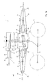
- Fig. 1 is a generic swath rotor 1 with the diameter D1 and the tine arms 2 in a simplified sectional view as a wire model, and in FIG. 2 the swath rotor 1 according to FIG. 1 is in a horizontal section A-A with Direction of view on the working level 60 shown.
- Fig. 1a shows one enlarged section of the swath according to Figure 1 in section.
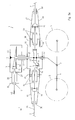
- Fig. 3, Fig. 3a and Fig. 4 show a larger swath rotor 1 'with the Diameter D2 analogous to the figure representations Fig.1, Fig.1a and Fig. 2, however with longer tine arms 2 ', which by an additional outer housing 18 and additional outer support bearing 30 are performed according to the invention.
- Figures 3b and 3c show variants of a swath rotor 1 ′ according to FIG. 3, 3a and 4 in a simplified version.
- a swath rotor 1 consist essentially of the in a known manner Tine arms 2 with the rake tines 3 attached, the tine arms 2 are pivotally mounted in an inner housing 8 in bearings 25.
- the Tine arms 2 predominantly extend perpendicular to the radial direction Gyro axis 4, however, at a tangential angle of attack ⁇ to the outside. All Tine arms 2 lie in the same rotation plane 29.
- the tine arms are in a known manner by means of a plug-in coupling 41 with safety plugs 42 securely connected to the control levers 12 of the cam track control 9.
- the swath rotor 2 is shown in a momentary rotational angle position is characterized by the tangential angle of attack ⁇ of a tine arm 2 with respect to a radius beam 55, which is aligned parallel to the direction of travel F.
- This angle of rotation position is the starting position of all others below shown swath, on the basis of which the inventive advantages of Invention are shown and described.
- the rake tines 3 are in their orbit around the rotary axis 4 of with rollers 11 control levers 12, which are controlled by a cam track 9 by a curved path 10 in its current orientation either in its Rake position 32 or in its raised position releasing the raked material 33 held.
- the swath rotor 1 is through to the ground on its working level 60 a chassis 56 supported.
- This consists essentially of the touch and Support wheels 5, which are interconnected by means of rockers 6 and which in a pivot point 7 are connected to the fixed gyro axis 4.
- Machine frame fixed gyro axis 4 is with the gear housing 14 a bevel gear 13 connected in the fixed point 17.
- The is driven Swath rotor 1 in a known manner, for example from the PTO Tractor or a hydraulic motor with the torque M1, which a Bevel gear pinion 15 drives, the bevel gear pinion 15 in the bearings 21, 21 'of Bearing neck 20 of the gear housing 14 is mounted.
- the bearing neck 20 supports its free end a mounting flange 35 on which the complete Swath rotor with the machine frame of a rotary swather in known Way is connectable.
- the bevel gear pinion 15 is in engagement with the drive side a ring gear 16, which with the inner housing 4 and thus with the Tine arms and their rake tines 3 are in a rotationally fixed connection.
- the non-rotatable connection between the ring gear 16 and the inner housing 8 is produced by the hollow shaft 24, the inner housing 8 being in supports the bearings 23, 23 'on the fixed gyro axis 4. It supports itself the hollow shaft 24 on the one hand in the bearing 23 on the other hand in the bearing 22 of the Gear housing 14 from.
- the tine arms 2 are thus about the gyroscopic axis 4 in the plane of rotation 19 driven in its direction of rotation 34. Due to the movement of the Tractor in the direction of travel F and by its direct drive through the PTO or by an indirect drive, for example by the on-board hydraulics, the rake tines of a swath rotor 1 move on the one hand in the direction of travel F on the other hand in the direction of rotation 34. Both types of movement, that of rotation and the translation together enable a mobile i.e. comprehensive Raking.
- Rotary swathers of this genus can be used both as single rotor and as Multi-rotor rakes should be designed.
- FIG. 3 and FIG. 4 a larger one is analogous to FIG. 1 and analogous to FIG Calculating gyro 1 'shown with the larger diameter D2. It is assumed that the units bevel gear 13, inner housing 8 including the Curve path control 9 exactly with each other in both arithmetic gyros 1 and 1 ' are identical. Rake gyroscope 1 with the diameter D1 differs in this respect only from the rake 2 with the diameter D2 in the length of the Tine arms 2 ', due to the larger diameter D2 Tine arms can be equipped with a larger number of rake tines2.
- the working width of the individual gyroscope determines a larger torque M2 at the Pinion shaft is present and due to this it can also be expected that the Support reactions. grow accordingly in the bearings 25 of the tine arms 2, the tine arms 2 'are supported in additional outer support bearings 30.
- This outer housing 18 can be formed, for example from an upper housing bell 27 and a lower housing bell 28. Both, the upper housing bell 27 and the lower housing bell 28 can by means of a screw connection 36 to be screwed to the inner housing 8 and therefore rely on this.
- the inner housing 8 with an upper Centering approach 26 and a lower centering approach 26 '. So are the upper bell 27 and the lower bell 28 by means of a flange connection, consisting of the centering projection 26, 26 'and the screw connection 36 by means of a flange connection with the inner housing 8 in a rotationally fixed manner interconnected.
- the outer bearings 30 are thus on the outer circumference of the outer Housing 18 positioned and they can by means of a simplification Screw connection, not shown, with the upper 27 and lower Housing bell 28 be screwed.
- This screw connection can also can be realized for example by a clamp connection by the Bearing housing of the bearings 30 between the upper 27 and the lower Bell housing 28 are clamped.
- FIG. 3b shows a simplified embodiment in accordance with the embodiment of FIG. 3a, by eliminating the lower bell housing 28.
- This is a Execution that differs from the embodiment according to FIG. 3 or FIG. 3a only has a lower rigidity and thus a lower stability, which however, in practice, depending on the conditions of use, it can be sufficient represents a cheaper variant of the embodiment shown in Fig. 3a.
- Figure 3c shows the execution of a gyro according to Figure 3b, but with a further simplification namely that of an inner housing 8 which is open at the bottom, which is generally known under the term open cam track.
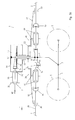
- FIGS. 1 and 2 are basically the same as in FIGS. 1 and 2 Swath rotor 1 'shown with the outer diameter D2.
- FIG. 6 the swath rotor according to FIG. 5 is in a horizontal section according to FIG Section C-C shown.
- the course of the cut is identical to that Rotation plane 29 of the tine arms.
- 5a is again an enlarged one Section of Fig. 5 shown.
- the spatial positioning of the compensating coupling 19 is thus made possible by the presence of a gap 57 which is formed by the spacing of an inner bearing 25 from its neighboring one outer support bearing 30.
- FIG. 5b again shows a simplified variant construction according to the Execution in Fig. 5a, i.e. without the lower housing bell 28 with again inner housing open at the bottom 8.
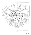
- FIGS. 7 and 8 show the swath rotor 1 "analogous to FIGS. 5 and 6, however, the tine arms 2 'an additional pivoting in the Rotation plane around the bending angle ⁇ compared to the tangential angle of attack ⁇ have experienced, so that the new tangential angle of attack ⁇ ' has stopped. This situation is shown in an enlarged detail in FIG. 8a shown in FIG. 8
- This change in the angle of attack ⁇ can be made possible by the compensating coupling 19 is designed, for example, as a universal joint 19 '.
- the outer housing 18 it is necessary to move the outer housing 18 around the centering projection 26, 26 ' of the inner housing 8 rotatable but also lockable.
- the upper housing bell 27 or under the housing bell 28 be equipped with a collar that centers around the respective centering approach 26,26 'rotatable and centered about the gyro axis 4.
- Locking can take place, for example, by a locking device 65 a spring-loaded snap bolt 31 take place.
- FIGS. 7b and 7c show a basic embodiment of a such locking device 65, Fig. 7b the locked and Fig. 7c the represents unlocked position of the snap bolt 31. More constructive Details can also be found in FIGS. 8a and 9b.
- the angled spring-loaded is known Snap bolt 31 in a guide housing 44 can be pivoted by approximately 180 Degree and at the same time axially displaceable by a compression spring 45 in the axial Biased and guided in the direction.
- the prestressed compression spring 45 is supported on the one hand on the upper contact surface 58 of the guide housing 44 and on the other hand on the lower contact surface 59, formed by a washer 46, which is below the washer 46 by a roll pin 47, which the transversely drilled latch bolt 31 penetrates from.
- By rotating the The latch bolt 31 slides the angled part of the latch bolt 31 over an inclined plane 61, which is also an axial Displacement of the latch bolt 31 causes.
- the guide housing 44 is, for example, with the upper housing bell 27 of the outer housing 18 welded and the snap bolt 31st then penetrates the wall of the bell housing 27 in the bore 63, depending on Position in position as shown in Fig. 7b, in the position bore 54 of the to engage inner housing 8, or as in the position as in Fig. 7b shown to release this position hole.
- FIG. 8b shows an enlarged section from FIG. 8a.
- the radian gives between 54 and 54 'the angle of rotation ⁇ within a step change of Hole pattern 64 on.
- the directional arrows + ⁇ and - ⁇ give the direction in which the tangential angle of attack ⁇ of the tine arms 2,2 'one Swath rotors 1,1 ', 1 "can be changed.
- Such an adjustment mechanism can thus be implemented, for example, in Step jumps with the angle of rotation ⁇ according to FIG. 8a or FIG. 8c, so that the Snap bolt 31 optionally in different position holes, for example 54 and 54 'can snap.
- the adjustment mechanism can Adjustment of the angle of attack ⁇ , as described under Fig. 8, in connection with a collision protection for swath rotor 1 ', 1 "can be expanded.
- Such a collision protection device in particular to protect the tine arms 2, 2 ' and other components of the cam track control 9 before breakage and plastic Deformations also to protect against broken teeth within the Bevel gear 13 is shown in FIGS. 9, 9a and 9b.
- the latch bolt 31, as described in FIGS. 7b and 7c, is shown in FIG modified the embodiment of FIG. 9 in such a way that its function is retained in principle, but the actual one remains Locking function of a spring-loaded steel ball 49 as a spear body is taken over.
- This steel ball 49 becomes analogous to the description in FIG. 7 and Fig. 8 of the compression spring 45 now from the spring bolt 43 in one Ball socket 48, which is part of the inner housing 8, as a locking body pushed.
- the steel ball 49 also protrudes into the Housing bore 63 of the outer housing 18 and thereby prevents Normal operation a relative twist between inner 8 and outer Housing 18, which with respect to a stable and permanent alignment of the set angle of attack ⁇ , ⁇ 'in the operating state of the rotary swather leads.
- the steel ball 49 loses its function as a blocking body, so that the tine arms, including the outer housing18, counter to the Direction of rotation 34 and thus relative to this now in the direction of rotation 34 ' can pivot the gyro axis 4 and thus avoid the obstacle.
- this effect can be used in conjunction with a gearbox Reversing the direction of rotation of a swath rotor in a special way to form small - so-called - night swaths can be used.
- the tine arms must also be replaced i.e. be adjusted to the direction of rotation. This is done, for example made possible by the tine arms with the compensating coupling 19,19 'by a Coupling device, for example by means of a plug-in coupling 42 are.
Landscapes
- Life Sciences & Earth Sciences (AREA)
- Environmental Sciences (AREA)
- Soil Working Implements (AREA)
- Harvester Elements (AREA)
- Retarders (AREA)
- Crystals, And After-Treatments Of Crystals (AREA)
- Polishing Bodies And Polishing Tools (AREA)
- Power Steering Mechanism (AREA)
Abstract
Description
- 1,1',1"
- Schwadkreisel
- 2,2'
- Zinkenarm
- 3
- Rechzinken
- 4
- Kreiselachse
- 5
- Tast- u. Stützrad
- 6
- Schwinge
- 7
- Drehpunkt
- 8
- Gehäuse
- 9
- Kurvenbahnsteuerung
- 10
- Kurvenbahn
- 11
- Laufrolle
- 12
- Steuerhebel
- 13
- Kegelradgetriebe
- 14
- Getriebegehäuse
- 15
- Kegelradritzel
- 16
- Tellerrad
- 17
- Fixpunkt
- 18
- Gehäuse
- 19
- Ausgleichskupplung
- 19'
- Kreuzgelenk
- 20
- Lagerhals
- 21,21'
- Lager
- 22
- Lager
- 23,23'
- Lager
- 24
- Hohlwelle
- 25
- Lager
- 26,26'
- Zentrieransatz
- 27
- obere Gehäuseglocke
- 28
- untere Gehäuseglocke
- 29
- Rotationsebene
- 30,30'
- äußeres Stützlager
- 31
- Schnappriegelbolzen
- 32
- Rechposition
- 33
- ausgehobene Position
- 34,34'
- Umlaufrichtung
- 35
- Befestigungsflansch
- 36
- Schraubverbindung
- 37
- Lagerbund
- 38,38'
- Umfangspunkt
- 39
- Abstand der Gelenke 8,8' in der Arbeitstellung
- 40
- Radius
- 41
- Steckkupplung
- 42
- Sicherungsstift
- 43
- Federbolzen
- 44
- Führungsgehäuse
- 45
- Druckfeder
- 46
- Unterlegscheibe
- 47
- Spannstift
- 48
- Kugelpfanne
- 49
- Stahlkugel
- 50
- Radius
- 51
- Ursprungsabstand
- 52
- Abstand
- 53
- Mittelpunkt
- 54,54'
- Positionsbohrung
- 55
- Radiusstrahl
- 56
- Fahrwerk
- 57
- Zwischenraum
- 58
- obere Anlagefläche
- 59
- untere Anlagefläche
- 60
- Arbeitsebene
- 61
- schiefe Ebene
- 62
- Schwenkachse
- 63
- Gehäusebohrung
- 64
- Lochbildmuster
- 65
- Feststelleinrichtung
- D1,D2,D2',D3
- Kreiseldurchmesser
- F
- Fahrtrichtung
- M1
- Antriebsdrehmoment
- M2
- Antriebsdrehmoment
- α,α',α",α"'
- Anstellwinkel
- β,β',β",β'"
- Beugewinkel
- δ,δ',δ"
- Verdrehwinkel
- Fig. 1
- zeigt einen gattungsgemäßen Schwadkreisel in einer Schnittdarstellung
- Fig. 1a
- zeigt einen vergrößerten Ausschnitt aus Fig.1
- Fig. 2
- zeigt einen gattungsgemäßen Schwadkreisel in einem Horizontalschnitt gemäß Schnitt A-A in Fig. 1
- Fig. 3
- zeigt einen erfindungsgemäßen Schwadkreisel in einer Schnittdarstellung
- Fig. 3a
- zeigt einen vergrößerten Ausschnitt aus Fig.3
- Fig. 3b
- zeigt eine Variantenkonstruktion zu Fig.3a
- Fig. 3c
- zeigt eine Variantenkonstruktion zu Fig.3b
- Fig. 4
- zeigt einen erfindungsgemäßen Schwadkreisel in einem Horizontalschnitt gemäß Schnitt B-B in Fig. 3
- Fig. 5
- zeigt einen erfindungsgemäßen Schwadkreisel in einer Schnittdarstellung
- Fig. 5a
- zeigt einen vergrößerten Ausschnitt aus Fig.5
- Fig. 5b
- zeigt eine Variantenkonstruktion zu Fig.5a
- Fig. 6
- zeigt einen erfindungsgemäßen Schwadkreisel in einem Horizontalschnitt gemäß Schnitt C-C der Fig. 5
- Fig. 7
- zeigt einen erfindungsgemäßen Schwadkreisel in einer Schnittdarstellung
- Fig. 7a
- zeigt einen vergrößerten Ausschnitt aus Fig.3
- Fig. 7b
- ein Verriegelungsmechanismus im gesperrten Zustand
- Fig. 7c
- ein Verriegelungsmechanismus im freigeschalteten Zustand
- Fig. 8
- zeigt einen erfindungsgemäßen Schwadkreisel in einer Draufsicht
- Fig. 8a
- zeigt einen vergrößerten Ausschnitt aus Fig.8
- Fig. 8b
- zeigt einen vergrößerten Ausschnitt aus Fig.8a
- Fig. 9
- zeigt einen erfindungsgemäßen Schwadkreisel in einer Draufsicht
- Fig. 9a
- zeigt ein Ausführungsbeispiel eines Kugel-Schnappriegelverschlusses in verriegelter Grundstellung
- Fig. 9b
- zeigt ein Ausführungsbeispiel eines Kugel-Schnappriegelverschlusses in ausgerasteter Stellung nach Überlast
- Fig. 10
- zeigt einen erfindungsgemäßen Schwadkreisel in einer Draufsicht in einer raumsparenden Transportstellung mit tangential angelegten Zinkenarmen
- Fig. 11
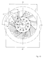
- zeigt einen erfindungsgemäßen Schwadkreisel in einer Draufsicht mit negativem tangentiale Anstellwinkel der Zinkenarme
Claims (26)
- Kreiselschwader zum Rechen und Schwaden von stengeligem Grünfuttererntegut mit mindestens einen um eine vertikale Kreiselachse (4) umlaufend angetriebenen mittels Tast und Stützräder (5) am Boden abgestützten Schwadkreisel (1), und ein Schwadkreisel (1) eine Kurvenbahnsteuerung (9) für gesteuerte an Zinkenarmen (2) befestigte Rechzinken (3) aufweist, und die Zinkenarme (2) endseitig der Kreiselachse (4) zugewandt mit Steuerhebel (12) bestückten Laufrollen (11) aufweisen, die mit der Kurvenbahnsteuerung (9) in Eingriff stehen, und die Steuerhebel (12) der Zinkenarme (2) in Lagern (25) als Teil eines um die Kreiselachse (4) umlaufend angetriebenen Gehäuse (8) gelagert sind, dadurch gekennzeichnet, dass ein Rechkreisel (1',1") ein erstes inneres Gehäuse (8) mit Lagern (25) und ein zweites äußeres Gehäuse (18) mit Lagern (30,30') für die Lagerung der Zinkenarmen (1,1',1") aufweist wobei das äußeres Gehäuse (18) an dem inneren Gehäuse (8) abgestützt ist.
- Kreiselschwader zum Rechen und Schwaden von stengeligem Erntegut mit mindestens einen um eine vertikale Kreiselachse (4) umlaufend angetriebenen mittels Tast und Stützräder (5) am Boden abgestützten Schwadkreisel (1), und ein Schwadkreisel (1) eine Kurvenbahnsteuerung (9) für gesteuerte an Zinkenarmen (2) befestigte Rechzinken (3) aufweist, und die Zinkenarme (2) endseitig der Kreiselachse zugewandt mit Steuerhebel (12) bestückten Laufrollen (11) aufweisen, die mit der Kurvenbahnsteuerung (9) in Eingriff stehen, und die Steuerhebel (12) der Zinkenarme (2) in Lagern (25) als Teil eines um die Kreiselachse (4) umlaufend angetriebenen Gehäuse (8) gelagert sind, dadurch gekennzeichnet, dass die Zinkenarme (2,2') so ausgebildet, gelagert und abgestützt sind, dass diese gegenüber der Drehachse der Lager (25) der Steuerhebel (12) einem Beugewinkel (β,β',β") ausgesetzt sein können.
- Kreiselschwader nach Anspruch 1 oder 2, dadurch gekennzeichnet, dass das erste inneres Gehäuse (8) Teil einer vollständigen und funktionsfähigen Basiseinheit, bestehend aus innerem Gehäuse (8), Kurvenbahnsteuerung (9) mit den Steuerelementen Kurvenbahn (10), Steuerhebeln (12), Laufrollen (11) und Lagern (25), darstellt.
- Kreiselschwader nach Anspruch 3, dadurch gekennzeichnet, dass das inneren Gehäuse (8) vollständig vom äußeren Gehäuse (18) umgeben ist.
- Kreiselschwader nach Anspruch 3, dadurch gekennzeichnet, dass das inneren Gehäuse (8) teilweise vom äußeren Gehäuse (18) umgeben ist.
- Kreiselschwader nach Anspruch 1 in Verbindung mit einem oder mehreren der vorhergehenden Ansprüche, dadurch gekennzeichnet, dass das äußeres Gehäuse (18) an dem inneren Gehäuse (8) mittels einer Schraubverbindung (36) mit diesem (8) abgestützt und verbunden ist.
- Kreiselschwader nach Anspruch 1 in Verbindung mit einem oder mehreren der vorhergehenden Ansprüche, dadurch gekennzeichnet, dass das äußeres Gehäuse (18) an dem inneren Gehäuse (8) mittels einer Schweißverbindung mit diesem (8) abgestützt und verbunden ist.
- Kreiselschwader nach Anspruch 1 in Verbindung mit einem oder mehreren der vorhergehenden Ansprüche, dadurch gekennzeichnet, dass die Steuerhebel (12) und die Zinkenarme (2 oder 2') durch eine Ausgleichskupplung (19), die zwischen den Lagern 25 und den Lagern (30,30') angeordnet sind, untereinander verbunden sind.
- Kreiselschwader nach Anspruch 1 in Verbindung mit einem oder mehreren der vorhergehenden Ansprüche, dadurch gekennzeichnet, dass die Ausgleichskupplung (19) so ausgebildet ist, dass diese Fluchtungsfehler zwischen den Lagern 25 und den Lagern (30,30') ausgleichen kann.
- Kreiselschwader nach Anspruch 1 in Verbindung mit einem oder mehreren der vorhergehenden Ansprüche, dadurch gekennzeichnet, dass die Ausgleichskupplung (19) als Kreuzgelenk 19' ausgebildet ist.
- Kreiselschwader nach Anspruch 1 in Verbindung mit einem oder mehreren der vorhergehenden Ansprüche, dadurch gekennzeichnet, dass das äußere Gehäuse (18) und dass innere Gehäuse (8) um die Kreiselachse (4) gelagert, relativ um einen Verdrehwinkel (δ,δ',δ") zueinander verdrehbar sind.
- Kreiselschwader nach Anspruch 1 in Verbindung mit einem oder mehreren der vorhergehenden Ansprüche, dadurch gekennzeichnet, dass das äußere Gehäuse (18) relativ zum inneren Gehäuse (8) verdrehbare, durch eine Feststelleinrichtung (65) in seiner Lage fixiert werden kann.
- Kreiselschwader nach Anspruch 1 in Verbindung mit einem oder mehreren der vorhergehenden Ansprüche, dadurch gekennzeichnet, dass das die Feststelleinrichtung (65) einen federbelasteten Schnappriegel aufweist.
- Kreiselschwader nach Anspruch 1 in Verbindung mit einem oder mehreren der vorhergehenden Ansprüche, dadurch gekennzeichnet, dass in Verbindung mit der relativen Verdrehung um einen Verdrehwinkel (δ,δ') des äußere Gehäuse (18) gegenüber dem inneren Gehäuse (8) ein Verstellmechanismus insgesamt gebildet werden kann, der eine Veränderbarkeit des tangentialen Eingriffswinkels (α,α') ermöglicht.
- Kreiselschwader nach Anspruch 1 in Verbindung mit einem oder mehreren der vorhergehenden Ansprüche, dadurch gekennzeichnet, dass der Verdrehwinkel (δ) in Stufensprüngen durch eine Feststelleinrichtung (65) veränderbar ist.
- Kreiselschwader nach Anspruch 1 in Verbindung mit einem oder mehreren der vorhergehenden Ansprüche, dadurch gekennzeichnet, dass das äußere Gehäuse (18) und dass innere Gehäuse (8) relativ zueinander verdrehbar um einen Verdrehwinkel (δ,δ',δ") um die Kreiselachse (4) eine Anfahrsicherung als Überlastsicherung beinhaltet.
- Kreiselschwader nach Anspruch 1 in Verbindung mit einem oder mehreren der vorhergehenden Ansprüche, dadurch gekennzeichnet, dass das äußere Gehäuse (18) aus geprägten Gehäuseglocken (27,28) besteht.
- Kreiselschwader nach Anspruch 1 in Verbindung mit einem oder mehreren der vorhergehenden Ansprüche, dadurch gekennzeichnet, dass das äußere Gehäuse (18) aus einer geprägten oberen Gehäuseglocken (27) besteht.
- Kreiselschwader nach Anspruch 1 in Verbindung mit einem oder mehreren der vorhergehenden Ansprüche, dadurch gekennzeichnet, dass ein äußere Stützlager (30,30') aus einem richtungsveränderbaren Schwenklager besteht.
- Kreiselschwader nach Anspruch 1 in Verbindung mit einem oder mehreren der vorhergehenden Ansprüche, dadurch gekennzeichnet, dass ein äußere Stützlager (30,30') als richtungsveränderbares Schwenklager beispielsweise aus einem Kugelgelenklager besteht.
- Kreiselschwader nach Anspruch 1 in Verbindung mit einem oder mehreren der vorhergehenden Ansprüche, dadurch gekennzeichnet, dass ein äußere Stützlager (30,30') als Axial- und Radiallager mit relativer Längsverschiebbarkeit eines Stützlagers (30,30') gegenüber den Zinkenarmen (2,2') ausgebildet ist
- Kreiselschwader nach Anspruch 1 in Verbindung mit einem oder mehreren der vorhergehenden Ansprüche, dadurch gekennzeichnet, dass durch die Veränderung des Beugewinkels (β) mit negativem Beugewinkel (-β) eine Veränderung der Umlaufrichtung (34,34') eines Schwadkreisels (1,1',1") möglich ist.
- Kreiselschwader nach Anspruch 1 in Verbindung mit einem oder mehreren der vorhergehenden Ansprüche, dadurch gekennzeichnet, dass die Zinkenarme (2,2') mittels einer Kupplungseinrichtung, beispielsweise ausgeführt als Steckkupplung 42, an - oder abgebaut werden können.
- Kreiselschwader nach Anspruch 1 in Verbindung mit einem oder mehreren der vorhergehenden Ansprüche, dadurch gekennzeichnet, dass die Zinkenarme (2,2') von links- oder rechtsdrehenden Schwadkreiseln durch eine Kupplungseinrichtung, beispielsweise ausgeführt als Steckkupplung 42, untereinander austauschbar sind.
- Kreiselschwader nach Anspruch 1 in Verbindung mit einem oder mehreren der vorhergehenden Ansprüche, dadurch gekennzeichnet, dass die Zinkenarme (2,2') von links- oder rechtsdrehenden Schwadkreiseln untereinander austauschbar sind.
- Kreiselschwader nach Anspruch 1 in Verbindung mit einem oder mehreren der vorhergehenden Ansprüche, dadurch gekennzeichnet, dass durch die Veränderung des Beugewinkels (β) der Kreiseldurchmesser (D2,D3) gegenüber den maximalen Kreiselduchmessers (D1) um mindestens 10 % verkleinerbar ist.
Applications Claiming Priority (2)
| Application Number | Priority Date | Filing Date | Title |
|---|---|---|---|
| DE10216474 | 2002-04-12 | ||
| DE10216474A DE10216474A1 (de) | 2002-04-12 | 2002-04-12 | Kreiselschwader |
Publications (2)
| Publication Number | Publication Date |
|---|---|
| EP1352553A1 true EP1352553A1 (de) | 2003-10-15 |
| EP1352553B1 EP1352553B1 (de) | 2008-02-13 |
Family
ID=28051309
Family Applications (1)
| Application Number | Title | Priority Date | Filing Date |
|---|---|---|---|
| EP03003498A Expired - Lifetime EP1352553B1 (de) | 2002-04-12 | 2003-02-14 | Kreiselschwader |
Country Status (4)
| Country | Link |
|---|---|
| EP (1) | EP1352553B1 (de) |
| AT (1) | ATE385678T1 (de) |
| DE (2) | DE10216474A1 (de) |
| PL (1) | PL216039B1 (de) |
Citations (10)
| Publication number | Priority date | Publication date | Assignee | Title |
|---|---|---|---|---|
| FR1562572A (de) * | 1967-05-05 | 1969-04-04 | ||
| DE1907337B1 (de) * | 1969-02-14 | 1970-01-29 | Stoll Walter Dipl Ing | Kreiselzettwender |
| DE2300969A1 (de) * | 1972-01-11 | 1973-07-26 | Poettinger Ohg Alois | Kreiselschwadrechen |
| FR2307458A1 (fr) * | 1975-04-18 | 1976-11-12 | Stoll Maschf Gmbh Wilhelm | Machine de fanage |
| FR2310080A1 (fr) * | 1975-05-05 | 1976-12-03 | Reber Walter | Machine de fenaison pour le fanage et l'andainage de fourrage |
| US4062174A (en) * | 1975-05-26 | 1977-12-13 | Wilhelm Stoll, Maschinenfabrik Gmbh | Hay-making machine |
| US4281506A (en) * | 1979-03-09 | 1981-08-04 | Belrecolt S.A. | Convertible forage-handling machine |
| AT366875B (de) * | 1976-02-06 | 1982-05-10 | Poettinger Ohg Alois | Heuwerbungsmaschine |
| EP0124837A1 (de) * | 1983-05-05 | 1984-11-14 | BUCHER-GUYER AG Maschinenfabrik | Heuwerbungsmaschine zum Zetten und Schwaden |
| EP0559023A1 (de) * | 1992-03-02 | 1993-09-08 | Maschinenfabrik Bernard Krone GmbH | Kreiselrechen für eine Heuwerbungsmaschine |
-
2002
- 2002-04-12 DE DE10216474A patent/DE10216474A1/de not_active Withdrawn
-
2003
- 2003-02-14 AT AT03003498T patent/ATE385678T1/de active
- 2003-02-14 DE DE50309137T patent/DE50309137D1/de not_active Expired - Lifetime
- 2003-02-14 EP EP03003498A patent/EP1352553B1/de not_active Expired - Lifetime
- 2003-04-01 PL PL359446A patent/PL216039B1/pl unknown
Patent Citations (10)
| Publication number | Priority date | Publication date | Assignee | Title |
|---|---|---|---|---|
| FR1562572A (de) * | 1967-05-05 | 1969-04-04 | ||
| DE1907337B1 (de) * | 1969-02-14 | 1970-01-29 | Stoll Walter Dipl Ing | Kreiselzettwender |
| DE2300969A1 (de) * | 1972-01-11 | 1973-07-26 | Poettinger Ohg Alois | Kreiselschwadrechen |
| FR2307458A1 (fr) * | 1975-04-18 | 1976-11-12 | Stoll Maschf Gmbh Wilhelm | Machine de fanage |
| FR2310080A1 (fr) * | 1975-05-05 | 1976-12-03 | Reber Walter | Machine de fenaison pour le fanage et l'andainage de fourrage |
| US4062174A (en) * | 1975-05-26 | 1977-12-13 | Wilhelm Stoll, Maschinenfabrik Gmbh | Hay-making machine |
| AT366875B (de) * | 1976-02-06 | 1982-05-10 | Poettinger Ohg Alois | Heuwerbungsmaschine |
| US4281506A (en) * | 1979-03-09 | 1981-08-04 | Belrecolt S.A. | Convertible forage-handling machine |
| EP0124837A1 (de) * | 1983-05-05 | 1984-11-14 | BUCHER-GUYER AG Maschinenfabrik | Heuwerbungsmaschine zum Zetten und Schwaden |
| EP0559023A1 (de) * | 1992-03-02 | 1993-09-08 | Maschinenfabrik Bernard Krone GmbH | Kreiselrechen für eine Heuwerbungsmaschine |
Also Published As
| Publication number | Publication date |
|---|---|
| ATE385678T1 (de) | 2008-03-15 |
| DE50309137D1 (de) | 2008-03-27 |
| PL359446A1 (en) | 2003-10-20 |
| PL216039B1 (pl) | 2014-02-28 |
| EP1352553B1 (de) | 2008-02-13 |
| DE10216474A1 (de) | 2003-10-23 |
Similar Documents
| Publication | Publication Date | Title |
|---|---|---|
| DE3031837C2 (de) | Landmaschine, insbesondere Kreiselheuwerbungsmaschine | |
| DE68909541T2 (de) | Mähmaschine mit verbessertem Rahmen. | |
| DE69017363T2 (de) | Mähmaschine mit verbesserter Entlastungsvorrichtung. | |
| EP0774202B1 (de) | Werkzeugträger | |
| EP1405556B1 (de) | Selbstfahrendes Grossflächenmähwerk | |
| DE68909559T2 (de) | Mähmaschine mit Schneidelementen. | |
| DE2426209B2 (de) | Landmaschine | |
| DE2822686C2 (de) | ||
| DE69001394T2 (de) | Landmaschine zum Schwaden mit zusammenklappbaren Werkzeugträgern. | |
| DE2814399A1 (de) | Erntemaschine | |
| DE69511739T2 (de) | Kreiselmäher mit Mähbalken und Traggestell | |
| DE10121014A1 (de) | Mähvorrichtung | |
| DE2858680C2 (de) | ||
| EP0667186B1 (de) | Walzenmühle | |
| EP1095555A1 (de) | Heuwerbungsmaschine | |
| DE68904246T2 (de) | Landmaschine mit mindestens einem waehrend der arbeit angetriebenen rechrad. | |
| EP0753247A1 (de) | Landwirtschaftliche Arbeitsmaschine, insbesondere Vielkreisel-Heuwender | |
| EP0399256B1 (de) | Laufradsteuerung für ein landwirtschaftliches Gerät,insbesondere für eine Heuwerbungsmaschine | |
| DE68916191T2 (de) | Landmaschine, insbesondere für die Heuwerbung mit einem mehrteiligen schwenkbaren Rahmen. | |
| DE2800500A1 (de) | Kreiselmaeher | |
| DE3218385C2 (de) | ||
| DE2224735A1 (de) | Heuwerbungsmaschine | |
| EP1352553B1 (de) | Kreiselschwader | |
| DE68902077T2 (de) | Mechanische lenkvorrichtung fuer die hinterraeder eines kraftfahrzeuges mit vierrad-lenkung. | |
| EP1258187B1 (de) | Antriebsanordnung für eine landwirtschaftliche Maschine |
Legal Events
| Date | Code | Title | Description |
|---|---|---|---|
| PUAI | Public reference made under article 153(3) epc to a published international application that has entered the european phase |
Free format text: ORIGINAL CODE: 0009012 |
|
| AK | Designated contracting states |
Kind code of ref document: A1 Designated state(s): AT BE BG CH CY CZ DE DK EE ES FI FR GB GR HU IE IT LI LU MC NL PT SE SI SK TR |
|
| AX | Request for extension of the european patent |
Extension state: AL LT LV MK RO |
|
| 17P | Request for examination filed |
Effective date: 20040415 |
|
| AKX | Designation fees paid |
Designated state(s): AT BE BG CH CY CZ DE DK EE ES FI FR GB GR HU IE IT LI LU MC NL PT SE SI SK TR |
|
| 17Q | First examination report despatched |
Effective date: 20061228 |
|
| GRAP | Despatch of communication of intention to grant a patent |
Free format text: ORIGINAL CODE: EPIDOSNIGR1 |
|
| GRAS | Grant fee paid |
Free format text: ORIGINAL CODE: EPIDOSNIGR3 |
|
| GRAA | (expected) grant |
Free format text: ORIGINAL CODE: 0009210 |
|
| AK | Designated contracting states |
Kind code of ref document: B1 Designated state(s): AT BE BG CH CY CZ DE DK EE ES FI FR GB GR HU IE IT LI LU MC NL PT SE SI SK TR |
|
| REG | Reference to a national code |
Ref country code: GB Ref legal event code: FG4D Free format text: NOT ENGLISH |
|
| REG | Reference to a national code |
Ref country code: CH Ref legal event code: EP |
|
| REG | Reference to a national code |
Ref country code: IE Ref legal event code: FG4D Free format text: LANGUAGE OF EP DOCUMENT: GERMAN |
|
| REF | Corresponds to: |
Ref document number: 50309137 Country of ref document: DE Date of ref document: 20080327 Kind code of ref document: P |
|
| REG | Reference to a national code |
Ref country code: DE Ref legal event code: R096 Ref document number: 50309137 Country of ref document: DE Effective date: 20080327 |
|
| PG25 | Lapsed in a contracting state [announced via postgrant information from national office to epo] |
Ref country code: FI Free format text: LAPSE BECAUSE OF FAILURE TO SUBMIT A TRANSLATION OF THE DESCRIPTION OR TO PAY THE FEE WITHIN THE PRESCRIBED TIME-LIMIT Effective date: 20080213 Ref country code: ES Free format text: LAPSE BECAUSE OF FAILURE TO SUBMIT A TRANSLATION OF THE DESCRIPTION OR TO PAY THE FEE WITHIN THE PRESCRIBED TIME-LIMIT Effective date: 20080524 |
|
| BERE | Be: lapsed |
Owner name: CLAAS SAULGAU G.M.B.H. Effective date: 20080228 |
|
| PG25 | Lapsed in a contracting state [announced via postgrant information from national office to epo] |
Ref country code: SI Free format text: LAPSE BECAUSE OF FAILURE TO SUBMIT A TRANSLATION OF THE DESCRIPTION OR TO PAY THE FEE WITHIN THE PRESCRIBED TIME-LIMIT Effective date: 20080213 |
|
| REG | Reference to a national code |
Ref country code: CH Ref legal event code: PL |
|
| REG | Reference to a national code |
Ref country code: IE Ref legal event code: FD4D |
|
| ET | Fr: translation filed | ||
| PG25 | Lapsed in a contracting state [announced via postgrant information from national office to epo] |
Ref country code: CH Free format text: LAPSE BECAUSE OF NON-PAYMENT OF DUE FEES Effective date: 20080229 Ref country code: MC Free format text: LAPSE BECAUSE OF NON-PAYMENT OF DUE FEES Effective date: 20080228 Ref country code: SK Free format text: LAPSE BECAUSE OF FAILURE TO SUBMIT A TRANSLATION OF THE DESCRIPTION OR TO PAY THE FEE WITHIN THE PRESCRIBED TIME-LIMIT Effective date: 20080213 Ref country code: SE Free format text: LAPSE BECAUSE OF FAILURE TO SUBMIT A TRANSLATION OF THE DESCRIPTION OR TO PAY THE FEE WITHIN THE PRESCRIBED TIME-LIMIT Effective date: 20080513 Ref country code: PT Free format text: LAPSE BECAUSE OF FAILURE TO SUBMIT A TRANSLATION OF THE DESCRIPTION OR TO PAY THE FEE WITHIN THE PRESCRIBED TIME-LIMIT Effective date: 20080714 Ref country code: DK Free format text: LAPSE BECAUSE OF FAILURE TO SUBMIT A TRANSLATION OF THE DESCRIPTION OR TO PAY THE FEE WITHIN THE PRESCRIBED TIME-LIMIT Effective date: 20080213 Ref country code: LI Free format text: LAPSE BECAUSE OF NON-PAYMENT OF DUE FEES Effective date: 20080229 Ref country code: CZ Free format text: LAPSE BECAUSE OF FAILURE TO SUBMIT A TRANSLATION OF THE DESCRIPTION OR TO PAY THE FEE WITHIN THE PRESCRIBED TIME-LIMIT Effective date: 20080213 Ref country code: IE Free format text: LAPSE BECAUSE OF FAILURE TO SUBMIT A TRANSLATION OF THE DESCRIPTION OR TO PAY THE FEE WITHIN THE PRESCRIBED TIME-LIMIT Effective date: 20080213 |
|
| PLBE | No opposition filed within time limit |
Free format text: ORIGINAL CODE: 0009261 |
|
| STAA | Information on the status of an ep patent application or granted ep patent |
Free format text: STATUS: NO OPPOSITION FILED WITHIN TIME LIMIT |
|
| 26N | No opposition filed |
Effective date: 20081114 |
|
| GBPC | Gb: european patent ceased through non-payment of renewal fee |
Effective date: 20080513 |
|
| PG25 | Lapsed in a contracting state [announced via postgrant information from national office to epo] |
Ref country code: EE Free format text: LAPSE BECAUSE OF FAILURE TO SUBMIT A TRANSLATION OF THE DESCRIPTION OR TO PAY THE FEE WITHIN THE PRESCRIBED TIME-LIMIT Effective date: 20080213 |
|
| PG25 | Lapsed in a contracting state [announced via postgrant information from national office to epo] |
Ref country code: BE Free format text: LAPSE BECAUSE OF NON-PAYMENT OF DUE FEES Effective date: 20080228 |
|
| REG | Reference to a national code |
Ref country code: DE Ref legal event code: R097 Ref document number: 50309137 Country of ref document: DE Effective date: 20081114 |
|
| PG25 | Lapsed in a contracting state [announced via postgrant information from national office to epo] |
Ref country code: BG Free format text: LAPSE BECAUSE OF FAILURE TO SUBMIT A TRANSLATION OF THE DESCRIPTION OR TO PAY THE FEE WITHIN THE PRESCRIBED TIME-LIMIT Effective date: 20080513 |
|
| PG25 | Lapsed in a contracting state [announced via postgrant information from national office to epo] |
Ref country code: GB Free format text: LAPSE BECAUSE OF NON-PAYMENT OF DUE FEES Effective date: 20080513 |
|
| PG25 | Lapsed in a contracting state [announced via postgrant information from national office to epo] |
Ref country code: CY Free format text: LAPSE BECAUSE OF FAILURE TO SUBMIT A TRANSLATION OF THE DESCRIPTION OR TO PAY THE FEE WITHIN THE PRESCRIBED TIME-LIMIT Effective date: 20080213 |
|
| PG25 | Lapsed in a contracting state [announced via postgrant information from national office to epo] |
Ref country code: IT Free format text: LAPSE BECAUSE OF FAILURE TO SUBMIT A TRANSLATION OF THE DESCRIPTION OR TO PAY THE FEE WITHIN THE PRESCRIBED TIME-LIMIT Effective date: 20080213 |
|
| PG25 | Lapsed in a contracting state [announced via postgrant information from national office to epo] |
Ref country code: HU Free format text: LAPSE BECAUSE OF FAILURE TO SUBMIT A TRANSLATION OF THE DESCRIPTION OR TO PAY THE FEE WITHIN THE PRESCRIBED TIME-LIMIT Effective date: 20080814 Ref country code: LU Free format text: LAPSE BECAUSE OF NON-PAYMENT OF DUE FEES Effective date: 20080214 |
|
| PG25 | Lapsed in a contracting state [announced via postgrant information from national office to epo] |
Ref country code: TR Free format text: LAPSE BECAUSE OF FAILURE TO SUBMIT A TRANSLATION OF THE DESCRIPTION OR TO PAY THE FEE WITHIN THE PRESCRIBED TIME-LIMIT Effective date: 20080213 |
|
| PG25 | Lapsed in a contracting state [announced via postgrant information from national office to epo] |
Ref country code: GR Free format text: LAPSE BECAUSE OF FAILURE TO SUBMIT A TRANSLATION OF THE DESCRIPTION OR TO PAY THE FEE WITHIN THE PRESCRIBED TIME-LIMIT Effective date: 20080514 |
|
| REG | Reference to a national code |
Ref country code: FR Ref legal event code: PLFP Year of fee payment: 14 |
|
| REG | Reference to a national code |
Ref country code: FR Ref legal event code: PLFP Year of fee payment: 15 |
|
| REG | Reference to a national code |
Ref country code: FR Ref legal event code: PLFP Year of fee payment: 16 |
|
| PGFP | Annual fee paid to national office [announced via postgrant information from national office to epo] |
Ref country code: NL Payment date: 20200219 Year of fee payment: 18 |
|
| REG | Reference to a national code |
Ref country code: NL Ref legal event code: MM Effective date: 20210301 |
|
| PG25 | Lapsed in a contracting state [announced via postgrant information from national office to epo] |
Ref country code: NL Free format text: LAPSE BECAUSE OF NON-PAYMENT OF DUE FEES Effective date: 20210301 |
|
| PGFP | Annual fee paid to national office [announced via postgrant information from national office to epo] |
Ref country code: DE Payment date: 20220217 Year of fee payment: 20 Ref country code: AT Payment date: 20220217 Year of fee payment: 20 |
|
| PGFP | Annual fee paid to national office [announced via postgrant information from national office to epo] |
Ref country code: FR Payment date: 20220216 Year of fee payment: 20 |
|
| REG | Reference to a national code |
Ref country code: DE Ref legal event code: R071 Ref document number: 50309137 Country of ref document: DE |
|
| REG | Reference to a national code |
Ref country code: AT Ref legal event code: MK07 Ref document number: 385678 Country of ref document: AT Kind code of ref document: T Effective date: 20230214 |
|
| P01 | Opt-out of the competence of the unified patent court (upc) registered |
Effective date: 20230517 |