EP1352171B1 - Finned plate heat exchanger - Google Patents
Finned plate heat exchanger Download PDFInfo
- Publication number
- EP1352171B1 EP1352171B1 EP01271497A EP01271497A EP1352171B1 EP 1352171 B1 EP1352171 B1 EP 1352171B1 EP 01271497 A EP01271497 A EP 01271497A EP 01271497 A EP01271497 A EP 01271497A EP 1352171 B1 EP1352171 B1 EP 1352171B1
- Authority
- EP
- European Patent Office
- Prior art keywords
- heat exchanger
- inlet
- cross
- manifolds
- base member
- Prior art date
- Legal status (The legal status is an assumption and is not a legal conclusion. Google has not performed a legal analysis and makes no representation as to the accuracy of the status listed.)
- Expired - Lifetime
Links
- 239000012530 fluid Substances 0.000 claims description 18
- 238000000034 method Methods 0.000 claims description 3
- WYTGDNHDOZPMIW-RCBQFDQVSA-N alstonine Natural products C1=CC2=C3C=CC=CC3=NC2=C2N1C[C@H]1[C@H](C)OC=C(C(=O)OC)[C@H]1C2 WYTGDNHDOZPMIW-RCBQFDQVSA-N 0.000 claims description 2
- 238000001816 cooling Methods 0.000 abstract description 3
- 239000000446 fuel Substances 0.000 description 15
- 229910052751 metal Inorganic materials 0.000 description 10
- 239000002184 metal Substances 0.000 description 10
- 239000000945 filler Substances 0.000 description 7
- 238000005219 brazing Methods 0.000 description 6
- 229910052782 aluminium Inorganic materials 0.000 description 5
- XAGFODPZIPBFFR-UHFFFAOYSA-N aluminium Chemical compound [Al] XAGFODPZIPBFFR-UHFFFAOYSA-N 0.000 description 5
- 238000009826 distribution Methods 0.000 description 5
- 210000002445 nipple Anatomy 0.000 description 5
- 238000004519 manufacturing process Methods 0.000 description 3
- 238000012986 modification Methods 0.000 description 3
- 230000004048 modification Effects 0.000 description 3
- 229910000838 Al alloy Inorganic materials 0.000 description 2
- 238000010276 construction Methods 0.000 description 2
- 238000001125 extrusion Methods 0.000 description 2
- 239000011888 foil Substances 0.000 description 2
- 230000004075 alteration Effects 0.000 description 1
- 238000005253 cladding Methods 0.000 description 1
- 239000002826 coolant Substances 0.000 description 1
- 239000002828 fuel tank Substances 0.000 description 1
- 238000009434 installation Methods 0.000 description 1
- 239000007788 liquid Substances 0.000 description 1
- 239000000203 mixture Substances 0.000 description 1
- 230000002093 peripheral effect Effects 0.000 description 1
- 238000005476 soldering Methods 0.000 description 1
- 239000007787 solid Substances 0.000 description 1
Images


Classifications
-
- F—MECHANICAL ENGINEERING; LIGHTING; HEATING; WEAPONS; BLASTING
- F28—HEAT EXCHANGE IN GENERAL
- F28F—DETAILS OF HEAT-EXCHANGE AND HEAT-TRANSFER APPARATUS, OF GENERAL APPLICATION
- F28F9/00—Casings; Header boxes; Auxiliary supports for elements; Auxiliary members within casings
- F28F9/02—Header boxes; End plates
- F28F9/026—Header boxes; End plates with static flow control means, e.g. with means for uniformly distributing heat exchange media into conduits
- F28F9/0278—Header boxes; End plates with static flow control means, e.g. with means for uniformly distributing heat exchange media into conduits in the form of stacked distribution plates or perforated plates arranged over end plates
-
- F—MECHANICAL ENGINEERING; LIGHTING; HEATING; WEAPONS; BLASTING
- F02—COMBUSTION ENGINES; HOT-GAS OR COMBUSTION-PRODUCT ENGINE PLANTS
- F02M—SUPPLYING COMBUSTION ENGINES IN GENERAL WITH COMBUSTIBLE MIXTURES OR CONSTITUENTS THEREOF
- F02M31/00—Apparatus for thermally treating combustion-air, fuel, or fuel-air mixture
- F02M31/20—Apparatus for thermally treating combustion-air, fuel, or fuel-air mixture for cooling
-
- F—MECHANICAL ENGINEERING; LIGHTING; HEATING; WEAPONS; BLASTING
- F28—HEAT EXCHANGE IN GENERAL
- F28D—HEAT-EXCHANGE APPARATUS, NOT PROVIDED FOR IN ANOTHER SUBCLASS, IN WHICH THE HEAT-EXCHANGE MEDIA DO NOT COME INTO DIRECT CONTACT
- F28D1/00—Heat-exchange apparatus having stationary conduit assemblies for one heat-exchange medium only, the media being in contact with different sides of the conduit wall, in which the other heat-exchange medium is a large body of fluid, e.g. domestic or motor car radiators
- F28D1/02—Heat-exchange apparatus having stationary conduit assemblies for one heat-exchange medium only, the media being in contact with different sides of the conduit wall, in which the other heat-exchange medium is a large body of fluid, e.g. domestic or motor car radiators with heat-exchange conduits immersed in the body of fluid
- F28D1/03—Heat-exchange apparatus having stationary conduit assemblies for one heat-exchange medium only, the media being in contact with different sides of the conduit wall, in which the other heat-exchange medium is a large body of fluid, e.g. domestic or motor car radiators with heat-exchange conduits immersed in the body of fluid with plate-like or laminated conduits
- F28D1/0308—Heat-exchange apparatus having stationary conduit assemblies for one heat-exchange medium only, the media being in contact with different sides of the conduit wall, in which the other heat-exchange medium is a large body of fluid, e.g. domestic or motor car radiators with heat-exchange conduits immersed in the body of fluid with plate-like or laminated conduits the conduits being formed by paired plates touching each other
-
- F—MECHANICAL ENGINEERING; LIGHTING; HEATING; WEAPONS; BLASTING
- F28—HEAT EXCHANGE IN GENERAL
- F28F—DETAILS OF HEAT-EXCHANGE AND HEAT-TRANSFER APPARATUS, OF GENERAL APPLICATION
- F28F3/00—Plate-like or laminated elements; Assemblies of plate-like or laminated elements
- F28F3/02—Elements or assemblies thereof with means for increasing heat-transfer area, e.g. with fins, with recesses, with corrugations
- F28F3/04—Elements or assemblies thereof with means for increasing heat-transfer area, e.g. with fins, with recesses, with corrugations the means being integral with the element
-
- F—MECHANICAL ENGINEERING; LIGHTING; HEATING; WEAPONS; BLASTING
- F28—HEAT EXCHANGE IN GENERAL
- F28F—DETAILS OF HEAT-EXCHANGE AND HEAT-TRANSFER APPARATUS, OF GENERAL APPLICATION
- F28F3/00—Plate-like or laminated elements; Assemblies of plate-like or laminated elements
- F28F3/12—Elements constructed in the shape of a hollow panel, e.g. with channels
-
- F—MECHANICAL ENGINEERING; LIGHTING; HEATING; WEAPONS; BLASTING
- F28—HEAT EXCHANGE IN GENERAL
- F28F—DETAILS OF HEAT-EXCHANGE AND HEAT-TRANSFER APPARATUS, OF GENERAL APPLICATION
- F28F9/00—Casings; Header boxes; Auxiliary supports for elements; Auxiliary members within casings
- F28F9/02—Header boxes; End plates
- F28F9/0246—Arrangements for connecting header boxes with flow lines
-
- F—MECHANICAL ENGINEERING; LIGHTING; HEATING; WEAPONS; BLASTING
- F28—HEAT EXCHANGE IN GENERAL
- F28D—HEAT-EXCHANGE APPARATUS, NOT PROVIDED FOR IN ANOTHER SUBCLASS, IN WHICH THE HEAT-EXCHANGE MEDIA DO NOT COME INTO DIRECT CONTACT
- F28D21/00—Heat-exchange apparatus not covered by any of the groups F28D1/00 - F28D20/00
- F28D2021/0019—Other heat exchangers for particular applications; Heat exchange systems not otherwise provided for
- F28D2021/008—Other heat exchangers for particular applications; Heat exchange systems not otherwise provided for for vehicles
- F28D2021/0091—Radiators
- F28D2021/0092—Radiators with particular location on vehicle, e.g. under floor or on roof
-
- Y—GENERAL TAGGING OF NEW TECHNOLOGICAL DEVELOPMENTS; GENERAL TAGGING OF CROSS-SECTIONAL TECHNOLOGIES SPANNING OVER SEVERAL SECTIONS OF THE IPC; TECHNICAL SUBJECTS COVERED BY FORMER USPC CROSS-REFERENCE ART COLLECTIONS [XRACs] AND DIGESTS
- Y02—TECHNOLOGIES OR APPLICATIONS FOR MITIGATION OR ADAPTATION AGAINST CLIMATE CHANGE
- Y02T—CLIMATE CHANGE MITIGATION TECHNOLOGIES RELATED TO TRANSPORTATION
- Y02T10/00—Road transport of goods or passengers
- Y02T10/10—Internal combustion engine [ICE] based vehicles
- Y02T10/12—Improving ICE efficiencies
Definitions
- the present invention relates to heat exchangers, and in particular, to heat exchangers useful as fuel coolers for automotive engines.
- EP 0 826 874 A2 shows a further heat exchanger in which flow channels are defined within a main body of a heat exchanger in which cooling fins or ribs are defined by the main body as well.
- FR 2,748,800 A shows a further heat exchanger configurations in which two plates having slots formed therein are sandwiched between two further plates.
- the slots in the internal plates cooperate to form flow paths and inlet and outlet manifolds.
- JP 62-9182 discloses a further example of a heat exchanger, which comprises an elongate base member having first and second side surfaces and including a plurality of spaced-apart fins extending from one of said first and second side surfaces, the base member being formed with spaced-apart, inlet and outlet manifolds; and inlet and outlet fittings communicating respectively with said inlet and outlet manifolds; the heat exchanger further comprising a cross-over member connected to the other of said first and second side surfaces and defining a flow channel for the flow of a heat exchange fluid the flow channel having inlet and outlet end portions communicating respectively with said inlet and outlet manifolds.
- heat exchangers are provided that are much simpler and easier to manufacture, and which require much less expensive tooling to make the required components.
- the elongate base member has a planar central portion
- the cross-over member is a plate having a groove formed therein defining said flow channel, the groove facing the planar central portion
- a method of forming a heat exchanger including the steps of: extruding a base member having a planar central portion and spaced-apart fins extending from one side of the planar central portion; forming a pair of spaced-apart flow manifolds in the base member; and forming spaced-apart openings in the planar central portion communicating with the flow manifolds; forming a cross-over member comprising a plate with a groove formed therein defining a flow channel; and attaching the cross-over member to the planar central portion, so that the flow manifolds and flow channel communicate with each other through said openings.
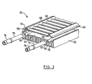
- Heat exchanger 10 is particularly useful as a fuel cooler and as such is an air cooled or liquid to air heat exchanger. It will be appreciated, however, that heat exchanger 10 can also be used to heat fluids, and it can also be used with fluids other than air and fuel.
- Heat exchanger 10 includes an elongate base member 12 which includes a planar central portion 14.
- Planar central portion 14 has an upper or first side surface 16 and a lower or second side surface 18.
- a plurality of spaced-apart fins 20 extend from the planar central portion 14. In the embodiment shown in Figures 1 and 2, fins 20 extend downwardly from the second side surface 18 but, as will be apparent from the following discussion, the fins 20 could extend upwardly or downwardly from planar central portion 14, as desired.
- the length, direction or orientation, and the spacing of fins 20 can be chosen to give predetermined or desired heat transfer characteristics to heat exchanger 10.
- Base member 12 also has upwardly extending peripheral side skirts 22 (see Figure 2) to help position the main components of heat exchanger 10, but side skirts 22 are not necessary and can be eliminated, if desired.
- Heat exchanger 10 also includes a cross-over member 24 which is connected to the other of the first and second side surfaces 16, 18, namely, to first side surface 16 as shown in Figures 1 and 2.
- Cross-over member 24 includes a first plate 26 located adjacent to the base member planar central portion 14.
- First plate 26 includes or defines a plurality of spaced-apart slots 28 therein which form spaced-apart flow channels for the flow of a heat exchange fluid, such as fuel, over the planar central portion 14.
- First plate 26 preferably is stamped to form slots 28. Slots 28 preferably are as long as possible and spaced as closely together as possible, yet keeping first plate 26 reasonably flat for assembly purposes, also to be described further below. If desired, slots 28 can be of different widths to vary the flow distribution across planar central portion 14. Also, expanded metal turbulizers could be located in slots 28, if desired.
- Cross-over member 24 also includes a second plate 30 which overlies first plate 26.
- Second plate 30 has a pair of spaced-apart slots 32, 34 formed therein which become flow manifolds for the supply and return of fuel from slots or flow channels 28.
- the flow manifolds 32, 34 communicate with the opposed distal end portions of flow channels 28, one of the end portions being an inlet end portion and the other of the end portions being an outlet end portion, depending upon which direction the fluid is flowing through heat exchanger 10.
- either of the flow manifolds 32 or 34 could be the inlet manifold, the other one being the outlet manifold, depending upon the direction in which the fluid flows through heat exchanger 10.
- flow manifolds or slots 32, 34 could be tapered if desired to help distribute the flow longitudinally along the heat exchanger.
- plates 26 and 30 could be reversed, so that plate 30 is the first plate and is located adjacent to the planar central portion 14, and plate 26 is the second plate and is located on top of plate 30.
- Cross-over member 24 also includes a third or cover plate 36 which overlies the second or manifold plate 30.
- Third or cover plate 36 has inlet and outlet openings 38, 40 formed therein that communicate with the respective slots or flow manifolds 32, 34 in second plate 30. Again, the direction of flow of fluid or fuel through heat exchanger 10 determines which of the openings 38, 40 is the inlet and which is the outlet.
- inlet and outlet elbows or fittings 42, 44 are attached to third or cover plate 36.
- Fittings 42, 44 have barbs or nipples 46, 48 for attaching hoses, such as fuel lines, to heat exchanger 10.
- Nipples 46, 48 thus communicate with inlet and outlet manifolds 32, 34 and thus in turn with flow channels 28.
- Base member 12 is preferably formed of aluminum or an aluminum alloy and is most conveniently made by extrusion, so that it can be made to any desired length simply by chopping or sawing the extrusion to a desired length.
- Plates 26, 30 and 36 are preferably stamped out of brazing clad aluminum.
- Fittings 42, 44 also are made of aluminum or an aluminum alloy.
- Heat exchanger 10 is made by assembling the components and furnace brazing or soldering them together.
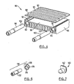
- Heat exchanger 50 also has an extruded aluminum base member 52 with a planar central portion 54 and spaced-apart fins 56, all of those components being similar to the embodiment of Figures 1 and 2.
- base member 52 is also formed with spaced-apart longitudinal grooves 58, 60 in planar central portion 54. These grooves 58, 60 extend from planar central portion 54 in the same direction as fins 56 and form partial inlet and outlet manifolds. These inlet and outlet manifolds are completed by cross-over member 62, as described next below.
- Cross-over member 62 is formed with a pair of longitudinal, spaced-apart, inverted, U-shaped grooves 64, 66 that also form partial inlet and outlet manifolds. Grooves 64, 66 co-operate with respective base member grooves 58, 60 to form the full inlet and outlet manifolds for heat exchanger 50.
- Cross-over member 62 is also formed with transverse, spaced-apart, inverted grooves or flow channels 68 (that appear as ribs in Figure 3), that communicate between the longitudinal grooves or flow manifolds 64, 66.
- Flow channels 68 are shown to be perpendicular to manifolds 64, 66, but they could be angled as well, if desired.
- Cross-over member 62 normally is roll formed, but it could be stamped if desired, in which case flow channels 68 could be of different widths or heights to vary the flow distribution inside heat exchanger 50.
- the cross-over member inlet and outlet manifolds 64, 66 overlie and communicate with the respective base member manifolds 58, 60 to form enlarged inlet and outlet manifolds for heat exchanger 50.
- Tubular fittings 70, 72 are then inserted into these flow manifolds. Fittings 70 and 72 have integral hose barbs or nipples 74, 76 for the attachment of hoses, such as fuel lines, to heat exchanger 50.
- suitable plugs (not shown) would be inserted into the manifolds formed by grooves 58, 64 and 60, 66.
- fittings 70, 72 could be located at opposite ends of heat exchanger 80, one fitting being associated with each of the manifolds 64, 66, and either one being the inlet fitting, the other one being the outlet fitting. The opposite ends of the manifolds 58, 64 and 60, 66 would be plugged.
- the inlet and outlet manifolds are partially formed in both the base member 52 and the cross-over member 62, but they could be formed only in the cross-over member 62.
- the planar central portion 54 would be flat and continuous as in the embodiment of Figures 1 and 2. Suitable modifications would be made to the shape of fittings 70, 72 to fit in a fluid tight manner into the inlet and outlet manifolds 64, 66.
- the partial inlet and outlet manifolds 58, 60 in base member 52 underlie and communicate with the respective cross-over member partial manifolds 64, 66 and together form enlarged inlet and outlet manifolds for heat exchanger 50.
- the partial inlet and outlet manifolds 64, 66 in cross-over member 62 overly and communicate with the respective base member partial manifold 58, 60 to form enlarged inlet and outlet manifolds for heat exchanger 50.
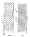
- Heat exchanger 80 is somewhat similar to heat exchanger 50 of Figure 3, except that the inlet and outlet manifolds 82, 84 are completely formed in base member 86.
- Cross-over member 88 is simply formed with transverse, inverted grooves 90 (again appearing as ribs in Figure 4) that define the flow channels therein.
- Inlet and outlet manifolds 82, 84 have upper slots 92, 94, and the grooves 90 face the planar central portion 96 and extend over the slots 92, 94 and thus between inlet and outlet manifolds 82, 84 for the flow of fluid or fuel over planar central portion 96.
- Grooves 90 could be of different widths along the length of heat exchanger 80.
- the grooves 90 close to the inlet and outlet of heat exchanger 80 could be of narrower width to reduce the tendency for short circuit flow between the inlet and outlet.
- Another possibility would be to put expanded metal turbulizers in grooves 90, especially near the heat exchanger inlet and outlet.
- slots 92, 94 could be replaced with longitudinally spaced-apart, transverse holes (see, for example, Figure 10), or a combination of holes and grooves, that communicate with manifolds 82, 84. Further, these holes could be of different sizes or spaced-apart at different intervals or locations along base member 86 to adjust the cross-flow between manifolds 82, 84 along the length of the heat exchanger. Of course, the spacing or size of flow channels 90 would be adjusted to suit these holes.
- Inlet fittings 98, 100 have raised longitudinal ribs or tabs 102 that plug the ends of slots 92, 94 to make a fluid tight connection with base member 86.
- ribs 102 could be eliminated if a shim is used as indicated in Figure 6, and as will be described further below.
- one large groove or depression in member 88 could be used instead of forming cross-over member 88 with grooves 90. In this case, it may be advantageous to place one or more expanded metal turbulizers in the cavity created by the one large groove 90 between plate 88 and planar central portion 96.
- Another possibility is to make cross-over member 88 a dimpled plate with the dimples extending downwardly to contact planar central portion 96.
- heat exchanger 80 is very similar to heat exchanger 50 of Figure 3. Again, fittings 98, 100 could be located at opposite ends of heat exchanger 80, one fitting being located in each of the manifolds 82, 84.
- heat exchanger 104 is yet another preferred embodiment according to the present invention.
- a pair of base members 106, 108 are stacked on top of each other with their respective planar central portions 110, 112 adjacent to each other.
- the cross-over member is formed of two halves or plates 114 and 116, Cross-over member plates 114, 116 are similar to the cross-over member 88 of Figure 4 in that they have transverse grooves 118 (again appearing as ribs in Figures 5) formed therein defining flow channels.
- the cross-over member plates 114, 116 are arranged back-to-back with their respective grooves 118 facing the planar central portions 110, 112.
- An inlet manifold 120 like inlet manifold 82 of the embodiment of Figure 4, is formed in one of the base members 106, and an outlet manifold 122, like that of outlet manifold 84 in the embodiment of Figure 4, is formed in the other of the base members 108.
- the grooves 118 of the cross-over members or plates 114, 116 are formed with transfer openings 124 located remote from inlet and outlet manifolds 120, 122 for passing heat exchange fluid between the back-to-back plates 114, 116. Otherwise, the construction of heat exchanger 104 is similar to heat exchanger 80 of Figure 4.
- fluid entering inlet manifold 120 through fitting 126 passes through flow channels 118 passing over central planar portion 110, then through openings 124 back through flow channels 118 of the lower half of heat exchanger 104, passing over central planar portion 112 and out through outlet fitting 128.
- FIG. 6 shows a modified fitting combination 130 that could be used for the inlet or outlet of either of the embodiments of Figures 4 or 5.
- Fitting combination 130 includes a nipple 132 much like the fittings 74, 76 of Figure 3, and also a shim 134.
- Shim 134 includes a tubular portion 136 that accommodates fitting 132 and fits snugly into the end of manifolds 82 or 84.
- Shim 134 also optionally includes a tab portion 138 that closes off the ends of the slots 92, 94 to provide a fluid-tight connection between the fittings and manifolds 82, 84.
- Shim 134 preferably is made of brazing clad aluminum or brazing sheet that has a clad filler metal on both surfaces, so that the shim 134 provides a source of filler metal to provide fluid-tight joints or seals for nipple 132.
- shims 134 could be made from or covered with filler metal foil.
- Figure 7 shows a plug 140 that can be used in any of the embodiments of Figures 3, 4 or 5 to close off the open ends of the inlet and outlet manifolds not containing an inlet or outlet fitting.
- Plug 140 also includes a tab portion 142 that closes off the ends of the slots 92, 94 to give a fluid-tight seal.
- Plug 140 preferably is made of brazing sheet with filler metal clad on at least the one side that contacts the inlet and outlet manifolds.
- filler metal wire preforms An alternative to using filler metal cladding or foil on the brazing sheet used to make shim 134 and plug 140 is the use filler metal wire preforms. Such filler metal wire preforms could also be used in place of shims 134.
- Figure 8 shows diagrammatically another configuration of a cross-over member 144 that could be used for the various cross-over members described above.
- cross-over member 144 could be used as the first plate 26 of the embodiment of Figures 1 and 2, in which case there would be flow channels 146 in the form of angled slots in plate 144.
- flow channels 146 would be angled grooves formed in plate member 144.
- the inlet side of plate 144 is indicated by arrow 148.
- Figure 9 is a diagrammatic view similar to Figure 8, but showing a cross-over member 150 formed of two overlapping plates that have angled flow channels 152, 154 that criss-cross. If cross-over member 150 is used in the embodiment of Figures 1 and 2, cross-over member 150 would take the place of both plates 26 and 30. A third or cover plate 36 would still be required. Preferable the inlet and outlet openings 38, 40 would be located at opposite corners of cross-over plate 150.
- cross-over member 150 is used for the embodiment of Figures 4 and 5, the uppermost plate would be a solid plate formed with grooves that define flow channels 152, much like cross-over members 88, 114 and 116, except that the flow channels are on an angle. Again, the flow channels in cross-over members 144, 150 can differ in width or spacing to vary the flow distribution inside their respective heat exchangers.
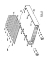
- Heat exchanger 156 is similar to the embodiment of Figure 4, except that base member 158 has a planar central portion 160 that includes a plurality of spaced-apart openings 162, 164 therethrough communicating with respective inlet and outlet manifolds 166, 168.
- Cross-over member 170 is formed with serpentine grooves or flow channels 172, each having an inlet end portion 174 and an outlet end portion 176 communicating with respective inlet and outlet openings 162, 164.
- Each serpentine flow channel 172 is shown having 3 passes or lengths, but there could be any odd number of passes, such as 5, 7, 9, or more passes between each of the inlet and outlet openings 162, 164. There could also be a mixture of flow channels containing different numbers of channels. Also, the widths of the flow channels could be varied as well as the diameters of the openings 162, 164 to vary the flow distribution inside heat exchanger 156.
- the method of making heat exchangers 10, 50, 80, 104 and 156 starts with the step of extruding the base members so that they have planar central portions and spaced-apart fins extending from one side of the planar central portions.
- the cross-over members are then formed by stamping the plates as in Figure 1 or stamping or roll forming the plates of the type shown in Figures 3, 4, 5 and 10.
- the base portions and/or the cross-over members are formed with a pair of spaced-apart flow manifolds and a plurality of spaced-apart transverse flow channels extend between the flow manifolds.
- the inlet and outlet fittings are then placed in position and the components are attached together.
- the flow manifolds and flow channels and inlet and outlet fittings thus communicate with the planar central portions to provide the heat transfer between fluid passing through the heat exchanger and the fluid, such as air, exposed to the fins of the base members.
- the heat exchangers have been shown having longitudinal fins, and transverse flow channels provided by the cross-over members. This provides a cross flow type heat exchanger.
- the flow channels of the cross-over members could be orientated in the same direction as the fins, in which case, a parallel flow heat exchanger would be provided.
- the heat exchangers described above have been shown to be rectangular or elongate, but they could be square as well. Different types of fittings could be used for attaching the heat exchangers into the fluid circuits into which they would be used, and the fittings can be located in different positions than those described above.
- the dimensions of the components described above can be varied to suit the application.
Landscapes
- Engineering & Computer Science (AREA)
- Mechanical Engineering (AREA)
- General Engineering & Computer Science (AREA)
- Thermal Sciences (AREA)
- Physics & Mathematics (AREA)
- Combustion & Propulsion (AREA)
- Chemical & Material Sciences (AREA)
- Heat-Exchange Devices With Radiators And Conduit Assemblies (AREA)
- Details Of Heat-Exchange And Heat-Transfer (AREA)
- Defrosting Systems (AREA)
- Separation By Low-Temperature Treatments (AREA)
- Steam Or Hot-Water Central Heating Systems (AREA)
- Filling Or Discharging Of Gas Storage Vessels (AREA)
Applications Claiming Priority (3)
| Application Number | Priority Date | Filing Date | Title |
|---|---|---|---|
| CA2329408 | 2000-12-21 | ||
| CA002329408A CA2329408C (en) | 2000-12-21 | 2000-12-21 | Finned plate heat exchanger |
| PCT/CA2001/001822 WO2002050419A1 (en) | 2000-12-21 | 2001-12-18 | Finned plate heat exchanger |
Publications (2)
| Publication Number | Publication Date |
|---|---|
| EP1352171A1 EP1352171A1 (en) | 2003-10-15 |
| EP1352171B1 true EP1352171B1 (en) | 2006-03-08 |
Family
ID=4167978
Family Applications (1)
| Application Number | Title | Priority Date | Filing Date |
|---|---|---|---|
| EP01271497A Expired - Lifetime EP1352171B1 (en) | 2000-12-21 | 2001-12-18 | Finned plate heat exchanger |
Country Status (11)
| Country | Link |
|---|---|
| US (1) | US6536516B2 (enExample) |
| EP (1) | EP1352171B1 (enExample) |
| JP (1) | JP4241044B2 (enExample) |
| KR (1) | KR100546869B1 (enExample) |
| CN (1) | CN100343500C (enExample) |
| AT (1) | ATE319926T1 (enExample) |
| AU (2) | AU1579002A (enExample) |
| CA (1) | CA2329408C (enExample) |
| CZ (1) | CZ299165B6 (enExample) |
| DE (1) | DE60117693T2 (enExample) |
| WO (1) | WO2002050419A1 (enExample) |
Cited By (1)
| Publication number | Priority date | Publication date | Assignee | Title |
|---|---|---|---|---|
| EP4421438A1 (de) * | 2023-02-27 | 2024-08-28 | Benteler Automobiltechnik GmbH | Wärmeübertragerplatte |
Families Citing this family (127)
| Publication number | Priority date | Publication date | Assignee | Title |
|---|---|---|---|---|
| US7295552B1 (en) * | 1999-06-30 | 2007-11-13 | Broadcom Corporation | Cluster switching architecture |
| US7011142B2 (en) * | 2000-12-21 | 2006-03-14 | Dana Canada Corporation | Finned plate heat exchanger |
| DE10125636B4 (de) * | 2001-05-25 | 2004-03-25 | Agilent Technologies, Inc. (n.d.Ges.d.Staates Delaware), Palo Alto | Kühler für elektrische und/oder elektronische Bauteile |
| CA2372399C (en) * | 2002-02-19 | 2010-10-26 | Long Manufacturing Ltd. | Low profile finned heat exchanger |
| US20070262162A1 (en) * | 2006-01-03 | 2007-11-15 | Karamanos John C | Limited loss laminar flow dampers for heating, ventilation, and air conditioning (hvac) systems |
| US11841159B2 (en) | 2002-03-06 | 2023-12-12 | John Chris Karamanos | Embedded heat exchanger with support mechanism |
| US8714236B2 (en) | 2007-01-10 | 2014-05-06 | John C. Karamanos | Embedded heat exchanger for heating, ventilatiion, and air conditioning (HVAC) systems and methods |
| USRE46708E1 (en) | 2002-03-06 | 2018-02-13 | John C. Karamanos | Embedded heat exchanger for heating, ventilation, and air conditioning (HVAC) systems and methods |
| US20030196451A1 (en) * | 2002-04-11 | 2003-10-23 | Lytron, Inc. | Contact cooling device |
| US8087452B2 (en) * | 2002-04-11 | 2012-01-03 | Lytron, Inc. | Contact cooling device |
| US8584738B2 (en) * | 2002-06-14 | 2013-11-19 | Lockheed Martin Corporation | Apparatus and method for extracting heat from a device |
| CA2392610C (en) * | 2002-07-05 | 2010-11-02 | Long Manufacturing Ltd. | Baffled surface cooled heat exchanger |
| US6988534B2 (en) * | 2002-11-01 | 2006-01-24 | Cooligy, Inc. | Method and apparatus for flexible fluid delivery for cooling desired hot spots in a heat producing device |
| US7000691B1 (en) * | 2002-07-11 | 2006-02-21 | Raytheon Company | Method and apparatus for cooling with coolant at a subambient pressure |
| US6994151B2 (en) | 2002-10-22 | 2006-02-07 | Cooligy, Inc. | Vapor escape microchannel heat exchanger |
| US6988535B2 (en) | 2002-11-01 | 2006-01-24 | Cooligy, Inc. | Channeled flat plate fin heat exchange system, device and method |
| US8464781B2 (en) * | 2002-11-01 | 2013-06-18 | Cooligy Inc. | Cooling systems incorporating heat exchangers and thermoelectric layers |
| WO2004042306A2 (en) | 2002-11-01 | 2004-05-21 | Cooligy, Inc. | Method and apparatus for achieving temperature uniformity and hot spot cooling in a heat producing device |
| US20050211417A1 (en) * | 2002-11-01 | 2005-09-29 | Cooligy,Inc. | Interwoven manifolds for pressure drop reduction in microchannel heat exchangers |
| US7156159B2 (en) | 2003-03-17 | 2007-01-02 | Cooligy, Inc. | Multi-level microchannel heat exchangers |
| US6986382B2 (en) * | 2002-11-01 | 2006-01-17 | Cooligy Inc. | Interwoven manifolds for pressure drop reduction in microchannel heat exchangers |
| US20050211427A1 (en) * | 2002-11-01 | 2005-09-29 | Cooligy, Inc. | Method and apparatus for flexible fluid delivery for cooling desired hot spots in a heat producing device |
| US7836597B2 (en) | 2002-11-01 | 2010-11-23 | Cooligy Inc. | Method of fabricating high surface to volume ratio structures and their integration in microheat exchangers for liquid cooling system |
| US7000684B2 (en) | 2002-11-01 | 2006-02-21 | Cooligy, Inc. | Method and apparatus for efficient vertical fluid delivery for cooling a heat producing device |
| US20090044928A1 (en) * | 2003-01-31 | 2009-02-19 | Girish Upadhya | Method and apparatus for preventing cracking in a liquid cooling system |
| US7201012B2 (en) | 2003-01-31 | 2007-04-10 | Cooligy, Inc. | Remedies to prevent cracking in a liquid system |
| US7293423B2 (en) * | 2004-06-04 | 2007-11-13 | Cooligy Inc. | Method and apparatus for controlling freezing nucleation and propagation |
| US7017654B2 (en) | 2003-03-17 | 2006-03-28 | Cooligy, Inc. | Apparatus and method of forming channels in a heat-exchanging device |
| CA2425233C (en) | 2003-04-11 | 2011-11-15 | Dana Canada Corporation | Surface cooled finned plate heat exchanger |
| DE10317705A1 (de) * | 2003-04-17 | 2004-10-28 | Robert Bosch Gmbh | Gehäuse mit Kühlung für elektronische Steuergeräte, insbesondere in Kfz |
| US7591302B1 (en) * | 2003-07-23 | 2009-09-22 | Cooligy Inc. | Pump and fan control concepts in a cooling system |
| US7596962B2 (en) | 2005-05-06 | 2009-10-06 | Karamanos John C | Shipping and installation for heating, ventilation, and air conditioning (HVAC) |
| WO2005028964A2 (en) * | 2003-09-17 | 2005-03-31 | Hvac-Sales, Inc. | Universal bracket and method for transporting an assembled conduit |
| US6951324B2 (en) * | 2003-09-17 | 2005-10-04 | John Chris Karamanos | Universal bracket for transporting an assembled conduit |
| ITTO20030743A1 (it) * | 2003-09-24 | 2005-03-25 | Dayco Fuel Man Spa | Dispositivo di raffreddamento per un circuito di ricircolo di carburante da un sistema di iniezione a un serbatorio di un autoveicolo |
| DK200301577A (da) * | 2003-10-27 | 2005-04-28 | Danfoss Silicon Power Gmbh | Flowfordelingsenhed og köleenhed |
| US6952345B2 (en) * | 2003-10-31 | 2005-10-04 | Raytheon Company | Method and apparatus for cooling heat-generating structure |
| US7182125B2 (en) * | 2003-11-28 | 2007-02-27 | Dana Canada Corporation | Low profile heat exchanger with notched turbulizer |
| JP2005274120A (ja) * | 2004-02-24 | 2005-10-06 | Showa Denko Kk | 液冷式冷却板 |
| US7280358B2 (en) * | 2004-04-19 | 2007-10-09 | Hewlett-Packard Development Company, L.P. | Liquid loop with multiple heat exchangers for efficient space utilization |
| US7002799B2 (en) * | 2004-04-19 | 2006-02-21 | Hewlett-Packard Development Company, L.P. | External liquid loop heat exchanger for an electronic system |
| US6997247B2 (en) * | 2004-04-29 | 2006-02-14 | Hewlett-Packard Development Company, L.P. | Multiple-pass heat exchanger with gaps between fins of adjacent tube segments |
| US20050262861A1 (en) * | 2004-05-25 | 2005-12-01 | Weber Richard M | Method and apparatus for controlling cooling with coolant at a subambient pressure |
| US7140236B2 (en) * | 2004-06-02 | 2006-11-28 | John Chris Karamanos | Method and system for controlling quality and tracking parts for repair and replacement in a piping system |
| US7616444B2 (en) * | 2004-06-04 | 2009-11-10 | Cooligy Inc. | Gimballed attachment for multiple heat exchangers |
| US7188662B2 (en) | 2004-06-04 | 2007-03-13 | Cooligy, Inc. | Apparatus and method of efficient fluid delivery for cooling a heat producing device |
| US20050274139A1 (en) * | 2004-06-14 | 2005-12-15 | Wyatt William G | Sub-ambient refrigerating cycle |
| US20060042785A1 (en) * | 2004-08-27 | 2006-03-02 | Cooligy, Inc. | Pumped fluid cooling system and method |
| JP4568581B2 (ja) * | 2004-11-02 | 2010-10-27 | カルソニックカンセイ株式会社 | プレート型熱交換器 |
| TWM267825U (en) * | 2004-11-03 | 2005-06-11 | Forward Electronics Co Ltd | Improved heat sink structure of liquid-cooling type heat sink device |
| US7117931B2 (en) * | 2004-12-31 | 2006-10-10 | Intel Corporation | Systems for low cost liquid cooling |
| JP4581964B2 (ja) * | 2005-02-14 | 2010-11-17 | セイコーエプソン株式会社 | マイクロチャンネル構造体の製造方法 |
| US7254957B2 (en) * | 2005-02-15 | 2007-08-14 | Raytheon Company | Method and apparatus for cooling with coolant at a subambient pressure |
| FR2883364B1 (fr) * | 2005-03-21 | 2007-09-28 | Roland Vilmart | Procede permettant d'assurer un echange thermique optimal au sein d'un ensemble constitue d'une plaque absorbante thermiquement conductrice et d'un fluide caloporteur |
| US9459015B2 (en) * | 2005-05-06 | 2016-10-04 | John Chris Karamanos | HVAC system and zone control unit |
| US9677777B2 (en) * | 2005-05-06 | 2017-06-13 | HVAC MFG, Inc. | HVAC system and zone control unit |
| DE102005029074B3 (de) * | 2005-06-23 | 2006-08-10 | Wieland-Werke Ag | Wärmeaustauscher für Kleinbauteile |
| US7658224B2 (en) * | 2005-09-19 | 2010-02-09 | Dana Canada Corporation | Flanged connection for heat exchanger |
| US7272006B2 (en) * | 2005-09-30 | 2007-09-18 | Intel Corporation | IC coolant microchannel assembly with integrated attachment hardware |
| US20070119572A1 (en) * | 2005-11-30 | 2007-05-31 | Raytheon Company | System and Method for Boiling Heat Transfer Using Self-Induced Coolant Transport and Impingements |
| US20070119568A1 (en) * | 2005-11-30 | 2007-05-31 | Raytheon Company | System and method of enhanced boiling heat transfer using pin fins |
| TW200805042A (en) | 2006-02-16 | 2008-01-16 | Cooligy Inc | Liquid cooling loops for server applications |
| JP4234722B2 (ja) * | 2006-02-28 | 2009-03-04 | 株式会社東芝 | 冷却装置および電子機器 |
| US20070209782A1 (en) * | 2006-03-08 | 2007-09-13 | Raytheon Company | System and method for cooling a server-based data center with sub-ambient cooling |
| TW200810676A (en) * | 2006-03-30 | 2008-02-16 | Cooligy Inc | Multi device cooling |
| US20070227709A1 (en) * | 2006-03-30 | 2007-10-04 | Girish Upadhya | Multi device cooling |
| US20070227698A1 (en) * | 2006-03-30 | 2007-10-04 | Conway Bruce R | Integrated fluid pump and radiator reservoir |
| US7715194B2 (en) * | 2006-04-11 | 2010-05-11 | Cooligy Inc. | Methodology of cooling multiple heat sources in a personal computer through the use of multiple fluid-based heat exchanging loops coupled via modular bus-type heat exchangers |
| US7908874B2 (en) | 2006-05-02 | 2011-03-22 | Raytheon Company | Method and apparatus for cooling electronics with a coolant at a subambient pressure |
| US20070256825A1 (en) * | 2006-05-04 | 2007-11-08 | Conway Bruce R | Methodology for the liquid cooling of heat generating components mounted on a daughter card/expansion card in a personal computer through the use of a remote drive bay heat exchanger with a flexible fluid interconnect |
| US20080006396A1 (en) * | 2006-06-30 | 2008-01-10 | Girish Upadhya | Multi-stage staggered radiator for high performance liquid cooling applications |
| US7624791B2 (en) * | 2006-09-08 | 2009-12-01 | Advanced Energy Industries, Inc. | Cooling apparatus for electronics |
| US9743563B2 (en) * | 2007-03-20 | 2017-08-22 | Conti Temic Microelectronic Gmbh | Control appliance for using in the engine compartment or in the transmission of a motor vehicle and cooling system for such a control appliance |
| US8651172B2 (en) * | 2007-03-22 | 2014-02-18 | Raytheon Company | System and method for separating components of a fluid coolant for cooling a structure |
| TW200912621A (en) * | 2007-08-07 | 2009-03-16 | Cooligy Inc | Method and apparatus for providing a supplemental cooling to server racks |
| US7921655B2 (en) | 2007-09-21 | 2011-04-12 | Raytheon Company | Topping cycle for a sub-ambient cooling system |
| US7940524B2 (en) * | 2007-10-01 | 2011-05-10 | Raytheon Company | Remote cooling of a phased array antenna |
| US7934386B2 (en) * | 2008-02-25 | 2011-05-03 | Raytheon Company | System and method for cooling a heat generating structure |
| US9297571B1 (en) | 2008-03-10 | 2016-03-29 | Liebert Corporation | Device and methodology for the removal of heat from an equipment rack by means of heat exchangers mounted to a door |
| US20090225514A1 (en) * | 2008-03-10 | 2009-09-10 | Adrian Correa | Device and methodology for the removal of heat from an equipment rack by means of heat exchangers mounted to a door |
| US7907409B2 (en) * | 2008-03-25 | 2011-03-15 | Raytheon Company | Systems and methods for cooling a computing component in a computing rack |
| US8490678B2 (en) * | 2008-06-02 | 2013-07-23 | Gerald Ho Kim | Silicon-based thermal energy transfer device and apparatus |
| JP5117287B2 (ja) * | 2008-06-06 | 2013-01-16 | 株式会社日立製作所 | 電子機器の冷却装置 |
| US8474516B2 (en) * | 2008-08-08 | 2013-07-02 | Mikros Manufacturing, Inc. | Heat exchanger having winding micro-channels |
| US20110226448A1 (en) * | 2008-08-08 | 2011-09-22 | Mikros Manufacturing, Inc. | Heat exchanger having winding channels |
| DE102008037852A1 (de) * | 2008-08-15 | 2010-02-18 | Robin Petrick | Plattenwärmetauscher |
| US7898810B2 (en) * | 2008-12-19 | 2011-03-01 | Raytheon Company | Air cooling for a phased array radar |
| JP5343574B2 (ja) * | 2009-01-20 | 2013-11-13 | トヨタ自動車株式会社 | ヒートシンクのろう付け方法 |
| TW201036527A (en) * | 2009-03-19 | 2010-10-01 | Acbel Polytech Inc | Large-area liquid-cooled heat-dissipation device |
| US20110022620A1 (en) * | 2009-07-27 | 2011-01-27 | Gemstar Development Corporation | Methods and systems for associating and providing media content of different types which share atrributes |
| DE102009051864B4 (de) * | 2009-11-04 | 2023-07-13 | Dr. Ing. H.C. F. Porsche Aktiengesellschaft | Kühlvorrichtung für eine elektrische Einrichtung |
| US8839519B2 (en) * | 2009-11-16 | 2014-09-23 | Raytheon Company | Method of making cold chassis for electronic modules |
| JP4951094B2 (ja) * | 2010-02-16 | 2012-06-13 | 株式会社東芝 | 電子機器の冷却構造 |
| US20110232887A1 (en) * | 2010-03-29 | 2011-09-29 | Zaffetti Mark A | Cold plate with integral structural fluid port |
| US20110317369A1 (en) * | 2010-06-29 | 2011-12-29 | General Electric Company | Heat sinks with millichannel cooling |
| US8218320B2 (en) | 2010-06-29 | 2012-07-10 | General Electric Company | Heat sinks with C-shaped manifolds and millichannel cooling |
| US8797741B2 (en) * | 2010-10-21 | 2014-08-05 | Raytheon Company | Maintaining thermal uniformity in micro-channel cold plates with two-phase flows |
| FR2967817B1 (fr) * | 2010-11-22 | 2013-08-16 | Solaire 2G | Panneau solaire hybride. |
| DE102011007748A1 (de) | 2011-04-20 | 2012-10-25 | Behr Gmbh & Co. Kg | Abgaskühler zum Kühlen von Verbrennungsabgas einer Verbrennungskraftmaschine, Wassersammeladapter, Abgaskühlsystem und Verfahren zum Herstellen eines Abgaskühlsystems |
| ITTO20111182A1 (it) * | 2011-12-21 | 2013-06-22 | Thesan S P A | Connessione per pannelli roll-bond |
| JP2015535070A (ja) * | 2012-11-08 | 2015-12-07 | ビーイー・エアロスペース・インコーポレーテッドB/E Aerospace, Inc. | 空気熱交換器間に配置された液体熱交換器を含む熱電冷却デバイス |
| CN104033966B (zh) * | 2013-03-06 | 2017-04-12 | 苏州昆拓热控系统股份有限公司 | 机柜空调器 |
| US9222862B2 (en) | 2013-03-12 | 2015-12-29 | John C. Karamanos | Piping stick systems and methods |
| CN104165413B (zh) * | 2013-05-20 | 2017-08-22 | 苏州昆拓热控系统股份有限公司 | 机柜空调器 |
| US9651316B2 (en) * | 2014-09-11 | 2017-05-16 | Ying Lin Cai | Thermal energy exchanger for bathing shower water |
| FR3030708B1 (fr) * | 2014-12-22 | 2018-02-16 | Airbus Operations Sas | Plaque froide, formant notamment partie structurale d'un equipement a composants generateurs de chaleur |
| ITUA20164171A1 (it) * | 2016-06-07 | 2017-12-07 | Fondital Spa | Dispositivo di riscaldamento |
| ITUA20164170A1 (it) * | 2016-06-07 | 2017-12-07 | Fondital Spa | Dispositivo di riscaldamento ad alta efficienza |
| ITUA20164166A1 (it) * | 2016-06-07 | 2017-12-07 | Fondital Spa | Dispositivo di riscaldamento e sistema modulare di riscaldamento con possibilita' di allestimento modulare in fase di installazione |
| CN107062972B (zh) * | 2017-04-27 | 2019-03-29 | 北京工业大学 | 一种扁管式相变蓄热装置 |
| TWI757553B (zh) * | 2017-10-13 | 2022-03-11 | 訊凱國際股份有限公司 | 脈衝式均溫板 |
| CN108105894B (zh) * | 2018-02-09 | 2024-05-24 | 珠海格力电器股份有限公司 | 热交换设备及空调器 |
| FR3086044B1 (fr) * | 2018-09-13 | 2020-08-21 | Valeo Systemes Thermiques | Echangeur de chaleur a reservoir de materiau a changement de phase |
| US10746084B2 (en) * | 2018-12-13 | 2020-08-18 | General Electric Company | Liquid driven thermal module and thermal management system |
| EP3686714A1 (en) * | 2019-01-25 | 2020-07-29 | Asetek Danmark A/S | Cooling system including a heat exchanging unit |
| FR3097627B1 (fr) * | 2019-06-18 | 2022-12-02 | Valeo Systemes Thermiques | Echangeur thermique à circulation de liquide et connecteur pour un tel échangeur |
| US10874037B1 (en) * | 2019-09-23 | 2020-12-22 | Ford Global Technologies, Llc | Power-module assembly with cooling arrangement |
| CN111678371B (zh) * | 2020-06-19 | 2022-02-18 | 贵州凯宏汇达冷却系统有限公司 | 一种换热器及基于其的液冷源设备 |
| CN114251861A (zh) * | 2020-09-24 | 2022-03-29 | 北京市京科伦工程设计研究院有限公司 | 一种高层建筑用单级二氧化碳中央空调 |
| IT202000031469A1 (it) * | 2020-12-18 | 2022-06-18 | Ufi Innovation Ct Srl | Dispositivo di regolazione termica |
| CN112902712A (zh) * | 2021-03-29 | 2021-06-04 | 浙江峰煌热交换器有限公司 | 一种芯片冷却换热器 |
| CN215912393U (zh) * | 2021-05-17 | 2022-02-25 | 深圳市英维克科技股份有限公司 | 一种冷却装置及电子设备 |
| KR20230073486A (ko) * | 2021-11-19 | 2023-05-26 | 한온시스템 주식회사 | 유체 가열 히터 |
| KR20230094013A (ko) | 2021-12-20 | 2023-06-27 | 현대자동차주식회사 | 파워모듈용 냉각장치 |
| CN116221683A (zh) * | 2022-12-29 | 2023-06-06 | 深圳市爱图仕影像器材有限公司 | 吸热组件、散热器和灯具 |
| DE102023202395A1 (de) * | 2023-03-16 | 2024-09-19 | Robert Bosch Gesellschaft mit beschränkter Haftung | Fluiddurchströmbarer Kühler zum Kühlen von mindestens zwei elektrischen und/oder elektronischen Baugruppen |
| FR3150280A1 (fr) * | 2023-06-20 | 2024-12-27 | Valeo Systemes Thermiques | Dispositif de régulation thermique |
Family Cites Families (24)
| Publication number | Priority date | Publication date | Assignee | Title |
|---|---|---|---|---|
| US2039593A (en) | 1935-06-20 | 1936-05-05 | Theodore N Hubbuch | Heat transfer coil |
| US4574876A (en) | 1981-05-11 | 1986-03-11 | Extracorporeal Medical Specialties, Inc. | Container with tapered walls for heating or cooling fluids |
| CN2045782U (zh) * | 1988-05-14 | 1989-10-11 | 石家庄新兴金属工艺加工厂 | 余热注入式汽车节油净化装置 |
| JPH036848A (ja) * | 1989-06-03 | 1991-01-14 | Hitachi Ltd | 半導体冷却モジュール |
| US5285347A (en) * | 1990-07-02 | 1994-02-08 | Digital Equipment Corporation | Hybird cooling system for electronic components |
| US5099311A (en) * | 1991-01-17 | 1992-03-24 | The United States Of America As Represented By The United States Department Of Energy | Microchannel heat sink assembly |
| US5381510A (en) | 1991-03-15 | 1995-01-10 | In-Touch Products Co. | In-line fluid heating apparatus with gradation of heat energy from inlet to outlet |
| US5159529A (en) * | 1991-05-15 | 1992-10-27 | International Business Machines Corporation | Composite liquid cooled plate for electronic equipment |
| US5205348A (en) | 1991-05-31 | 1993-04-27 | Minnesota Mining And Manufacturing Company | Semi-rigid heat transfer devices |
| US5316077A (en) * | 1992-12-09 | 1994-05-31 | Eaton Corporation | Heat sink for electrical circuit components |
| FR2701600B1 (fr) * | 1993-02-10 | 1995-09-08 | Gec Alsthom Transport Sa | Dispositif de refroidissement de composants electriques de puissance. |
| FR2701554B1 (fr) * | 1993-02-12 | 1995-05-12 | Transcal | Echangeur de chaleur pour composants électroniques et appareillages électro-techniques. |
| WO1994023257A1 (en) | 1993-03-29 | 1994-10-13 | Melanesia International Trust Company Limited | Heat exchanger assembly |
| DE19617396C2 (de) | 1996-05-02 | 1998-03-26 | Dornier Gmbh | Strömungsmodul |
| FR2748800A1 (fr) | 1996-05-15 | 1997-11-21 | Ferraz | Echangeur de chaleur pour composants electroniques et autres appareillages electro-techniques |
| DE19619934A1 (de) | 1996-05-17 | 1997-11-20 | Bayerische Motoren Werke Ag | Kraftstoffleitungssystem |
| DE59706596D1 (de) * | 1996-08-30 | 2002-04-18 | Volkswagen Ag | Einrichtung zur Kühlung des einem Verbrennungsmotor zugeführten Kraftstoffes |
| US5901037A (en) * | 1997-06-18 | 1999-05-04 | Northrop Grumman Corporation | Closed loop liquid cooling for semiconductor RF amplifier modules |
| DE19729857A1 (de) | 1997-07-11 | 1999-01-14 | Volkswagen Ag | Kraftfahrzeug mit Unterbodenwärmetauscher |
| DE29722841U1 (de) | 1997-12-24 | 1998-02-12 | Sander KG GmbH & Co., 77871 Renchen | Kühler für von der Einspritzpumpe oder Einspritzdüse zurückfließendes Dieselöl |
| FR2774463A1 (fr) | 1998-01-30 | 1999-08-06 | Peugeot | Module echangeur refroidisseur de fluide et utilisation du module echangeur refroidisseur |
| FR2774462B1 (fr) | 1998-01-30 | 2000-04-14 | Peugeot | Echangeur refroidisseur de fluide |
| FR2774635B1 (fr) | 1998-02-09 | 2000-04-21 | Valeo Thermique Moteur Sa | Dispositif de refroidissement du carburant d'un moteur de vehicule automobile |
| FR2785377B1 (fr) | 1998-10-29 | 2001-01-12 | Valeo Thermique Moteur Sa | Dispositif de refroidissement de carburant pour un moteur de vehicule automobile |
-
2000
- 2000-12-21 CA CA002329408A patent/CA2329408C/en not_active Expired - Lifetime
-
2001
- 2001-07-20 US US09/909,536 patent/US6536516B2/en not_active Expired - Lifetime
- 2001-12-18 AU AU1579002A patent/AU1579002A/xx active Pending
- 2001-12-18 CZ CZ20031996A patent/CZ299165B6/cs not_active IP Right Cessation
- 2001-12-18 CN CNB018209254A patent/CN100343500C/zh not_active Expired - Fee Related
- 2001-12-18 KR KR1020037008489A patent/KR100546869B1/ko not_active Expired - Fee Related
- 2001-12-18 WO PCT/CA2001/001822 patent/WO2002050419A1/en not_active Ceased
- 2001-12-18 AU AU2002215790A patent/AU2002215790B2/en not_active Ceased
- 2001-12-18 EP EP01271497A patent/EP1352171B1/en not_active Expired - Lifetime
- 2001-12-18 DE DE60117693T patent/DE60117693T2/de not_active Expired - Lifetime
- 2001-12-18 JP JP2002551282A patent/JP4241044B2/ja not_active Expired - Fee Related
- 2001-12-18 AT AT01271497T patent/ATE319926T1/de not_active IP Right Cessation
Cited By (2)
| Publication number | Priority date | Publication date | Assignee | Title |
|---|---|---|---|---|
| EP4421438A1 (de) * | 2023-02-27 | 2024-08-28 | Benteler Automobiltechnik GmbH | Wärmeübertragerplatte |
| EP4425085A1 (de) * | 2023-02-27 | 2024-09-04 | Benteler Automobiltechnik GmbH | Wärmeübertragerplatte |
Also Published As
| Publication number | Publication date |
|---|---|
| AU2002215790B2 (en) | 2005-03-10 |
| JP4241044B2 (ja) | 2009-03-18 |
| DE60117693D1 (de) | 2006-05-04 |
| EP1352171A1 (en) | 2003-10-15 |
| US6536516B2 (en) | 2003-03-25 |
| JP2004515742A (ja) | 2004-05-27 |
| CN1481472A (zh) | 2004-03-10 |
| WO2002050419A1 (en) | 2002-06-27 |
| CA2329408C (en) | 2007-12-04 |
| DE60117693T2 (de) | 2006-10-05 |
| CZ299165B6 (cs) | 2008-05-07 |
| ATE319926T1 (de) | 2006-03-15 |
| US20020079095A1 (en) | 2002-06-27 |
| KR20030086585A (ko) | 2003-11-10 |
| KR100546869B1 (ko) | 2006-01-25 |
| AU1579002A (en) | 2002-07-01 |
| CZ20031996A3 (cs) | 2004-11-10 |
| CN100343500C (zh) | 2007-10-17 |
| CA2329408A1 (en) | 2002-06-21 |
Similar Documents
| Publication | Publication Date | Title |
|---|---|---|
| EP1352171B1 (en) | Finned plate heat exchanger | |
| US7011142B2 (en) | Finned plate heat exchanger | |
| CA2425233C (en) | Surface cooled finned plate heat exchanger | |
| CA1313183C (en) | Embossed plate heat exchanger | |
| US5538077A (en) | In tank oil cooler | |
| CA2272804C (en) | Heat exchanger with dimpled bypass channel | |
| AU693694B2 (en) | Plate heat exchanger with improved undulating passageway | |
| US10451362B2 (en) | Heat exchanger having bypass seal with retention clip | |
| US7703505B2 (en) | Multifluid two-dimensional heat exchanger | |
| KR960005784B1 (ko) | 열교환기 | |
| US6938686B2 (en) | Lateral plate surface cooled heat exchanger | |
| US5476140A (en) | Alternately staggered louvered heat exchanger fin | |
| CA2431233A1 (en) | Finned plate heat exchanger |
Legal Events
| Date | Code | Title | Description |
|---|---|---|---|
| PUAI | Public reference made under article 153(3) epc to a published international application that has entered the european phase |
Free format text: ORIGINAL CODE: 0009012 |
|
| 17P | Request for examination filed |
Effective date: 20030714 |
|
| AK | Designated contracting states |
Kind code of ref document: A1 Designated state(s): AT BE CH CY DE DK ES FI FR GB GR IE IT LI LU MC NL PT SE TR |
|
| AX | Request for extension of the european patent |
Extension state: AL LT LV MK RO SI |
|
| 17Q | First examination report despatched |
Effective date: 20031031 |
|
| GRAP | Despatch of communication of intention to grant a patent |
Free format text: ORIGINAL CODE: EPIDOSNIGR1 |
|
| GRAS | Grant fee paid |
Free format text: ORIGINAL CODE: EPIDOSNIGR3 |
|
| GRAA | (expected) grant |
Free format text: ORIGINAL CODE: 0009210 |
|
| AK | Designated contracting states |
Kind code of ref document: B1 Designated state(s): AT BE CH CY DE DK ES FI FR GB GR IE IT LI LU MC NL PT SE TR |
|
| PG25 | Lapsed in a contracting state [announced via postgrant information from national office to epo] |
Ref country code: IT Free format text: LAPSE BECAUSE OF FAILURE TO SUBMIT A TRANSLATION OF THE DESCRIPTION OR TO PAY THE FEE WITHIN THE PRESCRIBED TIME-LIMIT;WARNING: LAPSES OF ITALIAN PATENTS WITH EFFECTIVE DATE BEFORE 2007 MAY HAVE OCCURRED AT ANY TIME BEFORE 2007. THE CORRECT EFFECTIVE DATE MAY BE DIFFERENT FROM THE ONE RECORDED. Effective date: 20060308 Ref country code: BE Free format text: LAPSE BECAUSE OF FAILURE TO SUBMIT A TRANSLATION OF THE DESCRIPTION OR TO PAY THE FEE WITHIN THE PRESCRIBED TIME-LIMIT Effective date: 20060308 Ref country code: CH Free format text: LAPSE BECAUSE OF FAILURE TO SUBMIT A TRANSLATION OF THE DESCRIPTION OR TO PAY THE FEE WITHIN THE PRESCRIBED TIME-LIMIT Effective date: 20060308 Ref country code: LI Free format text: LAPSE BECAUSE OF FAILURE TO SUBMIT A TRANSLATION OF THE DESCRIPTION OR TO PAY THE FEE WITHIN THE PRESCRIBED TIME-LIMIT Effective date: 20060308 Ref country code: NL Free format text: LAPSE BECAUSE OF FAILURE TO SUBMIT A TRANSLATION OF THE DESCRIPTION OR TO PAY THE FEE WITHIN THE PRESCRIBED TIME-LIMIT Effective date: 20060308 Ref country code: FI Free format text: LAPSE BECAUSE OF FAILURE TO SUBMIT A TRANSLATION OF THE DESCRIPTION OR TO PAY THE FEE WITHIN THE PRESCRIBED TIME-LIMIT Effective date: 20060308 Ref country code: AT Free format text: LAPSE BECAUSE OF FAILURE TO SUBMIT A TRANSLATION OF THE DESCRIPTION OR TO PAY THE FEE WITHIN THE PRESCRIBED TIME-LIMIT Effective date: 20060308 |
|
| REG | Reference to a national code |
Ref country code: GB Ref legal event code: FG4D |
|
| REG | Reference to a national code |
Ref country code: CH Ref legal event code: EP |
|
| REG | Reference to a national code |
Ref country code: IE Ref legal event code: FG4D |
|
| REF | Corresponds to: |
Ref document number: 60117693 Country of ref document: DE Date of ref document: 20060504 Kind code of ref document: P |
|
| PG25 | Lapsed in a contracting state [announced via postgrant information from national office to epo] |
Ref country code: DK Free format text: LAPSE BECAUSE OF FAILURE TO SUBMIT A TRANSLATION OF THE DESCRIPTION OR TO PAY THE FEE WITHIN THE PRESCRIBED TIME-LIMIT Effective date: 20060608 Ref country code: SE Free format text: LAPSE BECAUSE OF FAILURE TO SUBMIT A TRANSLATION OF THE DESCRIPTION OR TO PAY THE FEE WITHIN THE PRESCRIBED TIME-LIMIT Effective date: 20060608 |
|
| PG25 | Lapsed in a contracting state [announced via postgrant information from national office to epo] |
Ref country code: ES Free format text: LAPSE BECAUSE OF FAILURE TO SUBMIT A TRANSLATION OF THE DESCRIPTION OR TO PAY THE FEE WITHIN THE PRESCRIBED TIME-LIMIT Effective date: 20060619 |
|
| PG25 | Lapsed in a contracting state [announced via postgrant information from national office to epo] |
Ref country code: PT Free format text: LAPSE BECAUSE OF FAILURE TO SUBMIT A TRANSLATION OF THE DESCRIPTION OR TO PAY THE FEE WITHIN THE PRESCRIBED TIME-LIMIT Effective date: 20060808 |
|
| NLV1 | Nl: lapsed or annulled due to failure to fulfill the requirements of art. 29p and 29m of the patents act | ||
| REG | Reference to a national code |
Ref country code: CH Ref legal event code: PL |
|
| ET | Fr: translation filed | ||
| PG25 | Lapsed in a contracting state [announced via postgrant information from national office to epo] |
Ref country code: IE Free format text: LAPSE BECAUSE OF NON-PAYMENT OF DUE FEES Effective date: 20061218 |
|
| PG25 | Lapsed in a contracting state [announced via postgrant information from national office to epo] |
Ref country code: MC Free format text: LAPSE BECAUSE OF NON-PAYMENT OF DUE FEES Effective date: 20061231 |
|
| PLBE | No opposition filed within time limit |
Free format text: ORIGINAL CODE: 0009261 |
|
| STAA | Information on the status of an ep patent application or granted ep patent |
Free format text: STATUS: NO OPPOSITION FILED WITHIN TIME LIMIT |
|
| 26N | No opposition filed |
Effective date: 20061211 |
|
| PG25 | Lapsed in a contracting state [announced via postgrant information from national office to epo] |
Ref country code: GR Free format text: LAPSE BECAUSE OF FAILURE TO SUBMIT A TRANSLATION OF THE DESCRIPTION OR TO PAY THE FEE WITHIN THE PRESCRIBED TIME-LIMIT Effective date: 20060609 |
|
| PG25 | Lapsed in a contracting state [announced via postgrant information from national office to epo] |
Ref country code: LU Free format text: LAPSE BECAUSE OF NON-PAYMENT OF DUE FEES Effective date: 20061218 Ref country code: TR Free format text: LAPSE BECAUSE OF FAILURE TO SUBMIT A TRANSLATION OF THE DESCRIPTION OR TO PAY THE FEE WITHIN THE PRESCRIBED TIME-LIMIT Effective date: 20060308 |
|
| PG25 | Lapsed in a contracting state [announced via postgrant information from national office to epo] |
Ref country code: CY Free format text: LAPSE BECAUSE OF FAILURE TO SUBMIT A TRANSLATION OF THE DESCRIPTION OR TO PAY THE FEE WITHIN THE PRESCRIBED TIME-LIMIT Effective date: 20060308 |
|
| PGFP | Annual fee paid to national office [announced via postgrant information from national office to epo] |
Ref country code: DE Payment date: 20091230 Year of fee payment: 9 |
|
| REG | Reference to a national code |
Ref country code: DE Ref legal event code: R119 Ref document number: 60117693 Country of ref document: DE Effective date: 20110701 |
|
| PG25 | Lapsed in a contracting state [announced via postgrant information from national office to epo] |
Ref country code: DE Free format text: LAPSE BECAUSE OF NON-PAYMENT OF DUE FEES Effective date: 20110701 |
|
| PGFP | Annual fee paid to national office [announced via postgrant information from national office to epo] |
Ref country code: GB Payment date: 20121227 Year of fee payment: 12 |
|
| GBPC | Gb: european patent ceased through non-payment of renewal fee |
Effective date: 20131218 |
|
| PG25 | Lapsed in a contracting state [announced via postgrant information from national office to epo] |
Ref country code: GB Free format text: LAPSE BECAUSE OF NON-PAYMENT OF DUE FEES Effective date: 20131218 |
|
| REG | Reference to a national code |
Ref country code: FR Ref legal event code: PLFP Year of fee payment: 15 |
|
| REG | Reference to a national code |
Ref country code: FR Ref legal event code: PLFP Year of fee payment: 16 |
|
| REG | Reference to a national code |
Ref country code: FR Ref legal event code: PLFP Year of fee payment: 17 |
|
| PGFP | Annual fee paid to national office [announced via postgrant information from national office to epo] |
Ref country code: FR Payment date: 20191226 Year of fee payment: 19 |
|
| PG25 | Lapsed in a contracting state [announced via postgrant information from national office to epo] |
Ref country code: FR Free format text: LAPSE BECAUSE OF NON-PAYMENT OF DUE FEES Effective date: 20201231 |