EP1352134B1 - Riegel-pfosten-konstruktion - Google Patents
Riegel-pfosten-konstruktion Download PDFInfo
- Publication number
- EP1352134B1 EP1352134B1 EP02702252A EP02702252A EP1352134B1 EP 1352134 B1 EP1352134 B1 EP 1352134B1 EP 02702252 A EP02702252 A EP 02702252A EP 02702252 A EP02702252 A EP 02702252A EP 1352134 B1 EP1352134 B1 EP 1352134B1
- Authority
- EP
- European Patent Office
- Prior art keywords
- transom
- connecting part
- structure according
- mullion
- groove
- Prior art date
- Legal status (The legal status is an assumption and is not a legal conclusion. Google has not performed a legal analysis and makes no representation as to the accuracy of the status listed.)
- Expired - Lifetime
Links
- 239000011521 glass Substances 0.000 claims abstract description 21
- 239000007788 liquid Substances 0.000 claims abstract description 8
- 230000008878 coupling Effects 0.000 claims description 20
- 238000010168 coupling process Methods 0.000 claims description 20
- 238000005859 coupling reaction Methods 0.000 claims description 20
- 230000002093 peripheral effect Effects 0.000 claims description 5
- 238000007789 sealing Methods 0.000 claims description 5
- 150000001875 compounds Chemical class 0.000 claims description 4
- 230000015572 biosynthetic process Effects 0.000 claims 1
- 230000000717 retained effect Effects 0.000 claims 1
- 238000010276 construction Methods 0.000 description 16
- 238000004873 anchoring Methods 0.000 description 7
- 239000000565 sealant Substances 0.000 description 4
- 239000000853 adhesive Substances 0.000 description 3
- 230000001070 adhesive effect Effects 0.000 description 3
- 230000007704 transition Effects 0.000 description 3
- 239000002184 metal Substances 0.000 description 2
- 238000000034 method Methods 0.000 description 2
- 238000004026 adhesive bonding Methods 0.000 description 1
- 238000005520 cutting process Methods 0.000 description 1
- 238000007599 discharging Methods 0.000 description 1
- 238000005516 engineering process Methods 0.000 description 1
- 238000005304 joining Methods 0.000 description 1
- ORQBXQOJMQIAOY-UHFFFAOYSA-N nobelium Chemical compound [No] ORQBXQOJMQIAOY-UHFFFAOYSA-N 0.000 description 1
- 238000003466 welding Methods 0.000 description 1
Images



Classifications
-
- E—FIXED CONSTRUCTIONS
- E04—BUILDING
- E04B—GENERAL BUILDING CONSTRUCTIONS; WALLS, e.g. PARTITIONS; ROOFS; FLOORS; CEILINGS; INSULATION OR OTHER PROTECTION OF BUILDINGS
- E04B2/00—Walls, e.g. partitions, for buildings; Wall construction with regard to insulation; Connections specially adapted to walls
- E04B2/88—Curtain walls
- E04B2/96—Curtain walls comprising panels attached to the structure through mullions or transoms
- E04B2/965—Connections of mullions and transoms
-
- E—FIXED CONSTRUCTIONS
- E04—BUILDING
- E04D—ROOF COVERINGS; SKY-LIGHTS; GUTTERS; ROOF-WORKING TOOLS
- E04D3/00—Roof covering by making use of flat or curved slabs or stiff sheets
- E04D3/02—Roof covering by making use of flat or curved slabs or stiff sheets of plane slabs, slates, or sheets, or in which the cross-section is unimportant
- E04D3/06—Roof covering by making use of flat or curved slabs or stiff sheets of plane slabs, slates, or sheets, or in which the cross-section is unimportant of glass or other translucent material; Fixing means therefor
- E04D3/08—Roof covering by making use of flat or curved slabs or stiff sheets of plane slabs, slates, or sheets, or in which the cross-section is unimportant of glass or other translucent material; Fixing means therefor with metal glazing bars
- E04D2003/0868—Mutual connections and details of glazing bars
Definitions
- the present invention relates to a transom-post construction, in particular for facades or skylights, in the frame fields glass are inserted, with a plurality of posts between which bars are fixed, the posts on an outer surface at the edge each have a groove for receiving a seal and adjacent to the groove, a drainage groove for discharging liquid is arranged, wherein the bolt on the side facing the outer surface of the post edge each having a groove for receiving a seal and between the grooves has a retaining strip.
- the metal framework includes posts and transversely extending latch, each having a groove for receiving a seal at the edge, to store a glass pane peripherally circumferentially on a seal.
- To determine the glass cover profiles are provided, which can be screwed with appropriate anchoring grooves on the bars and posts. Between the anchoring grooves and the grooves for receiving the seals drainage grooves are provided both on the bar and on the post, in order to derive liquid that enters between the anchoring and the glass pane on the bar or post.
- the bolt engages over the end of the post in the groove for receiving the seal and is therefore slightly higher than the post.
- a connecting part is attached to the end face, which extends the grooves and the retaining strip of the bolt and at least partially covers the edge groove of the post, initially the overlapping construction is maintained, the functions of the grooves and the retaining strip of the bolt also in the edge region of the post.
- the bolt can be easily mounted by sawing the bolt to the desired length. Subsequently, it is mounted between two posts, wherein the connecting part is fastened either beforehand to the bar or subsequently to the bar.
- the bolt is thus held with small tolerances between the post, as only once a sawing of the bolt takes place and not as in the prior art, a cutting to length of the bolt and then a notching of the bolt is required. In addition, this facilitates the assembly of the bolt, so that the additional costs incurred by the connecting part not negatively.
- the connecting part is fixed to the bolt.
- the type of fixing the expert is basically free, since all the usual fastening methods, such as screwing, gluing, Welding or other joining techniques are possible.
- a mechanical fastening is used.
- this is preferably held on the bolt by means of a coupling member which is inserted into an undercut groove on the bolt and on the connecting part.
- the coupling part can be positively and non-positively inserted into the groove on the bolt, so that at least a prefixing of the coupling part is given.
- the connecting part can be held in a simple manner adjacent to the bolt profile, without a tool is required during the pre-assembly. So that the C-shaped portion does not obstruct the support of the connecting part on the post, the leg arranged at the bottom of the connecting part is preferably received in the peripheral drainage groove on the post.
- the latch on both sides of the retaining strip on a drainage groove in each of which a coupling part is inserted. It can be provided on the coupling part and channels for the discharge of liquid in order to maintain the function of the drainage groove.
- webs are formed on the connecting part, which bear against the bolt.
- webs are formed on the connecting part, which bear against the groove walls and / or the retaining strip of the bolt.
- the connecting part can be prefixed to the bolt without an additional component.
- the webs can lie positively against the profile surface of the bolt, so that the connecting part is movable at most in the axial direction of the bolt.
- At least one recess is provided on the front side of the bolt, through which a web of the connecting part is inserted. This allows a jetty below engage the groove bottom or the bottom of the retaining strip to allow a planar support of the connecting part.
- a hollow chamber is formed below the connecting part, into which a sealant for sealing a drainage groove formed on the latch and the connecting part can be inserted.
- a sealant for sealing a drainage groove formed on the latch and the connecting part can be inserted.
- the connecting piece is screwed to the peripheral groove on the post.
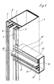
- the bolt-post construction comprises a vertical post 1, at which a bolt 2 connects at right angles.
- the latch 2 at a different angle to the post 1.
- grooves 3 and 4 are provided on the edge for receiving a glass mounting seal.
- a drainage groove 8 is provided.
- the post 1 comprises an anchoring strip 9 into which a mounting element 102 can be inserted.
- glass panels 100 can be inserted into the fields formed by posts 1 and 2 bars, which then rest on the glass mounting seals 5, 6 and 12. The glass sheets 100 are fixed by means not shown cover strips on the mounting member 102 and thus on the post 1 and the bolt 2.
- Fig. 2 schematically individual droplets are shown, which represent the entry of moisture between the glass pane 100 and the drainage groove 14 of the bolt 2 should.
- the moisture is discharged via the drainage grooves 14 and 15 on the latch 2 to the drainage groove 7 on the post 1 and derived from the transom-post construction.
- the glass sheets 100 are not affected by this, as they rest on the glass support seals 5 and 12, wherein the height difference is compensated for the glass out by different high glass contact seals 5 and 12 respectively.
- a retaining strip 13 is centrally provided, which is surrounded on both sides by drainage grooves 14 and 15.
- the overlapping region adjacent to the groove 3 of the post 1 is formed by a connecting part 20, which is formed separately from the latch 2 and is fixed thereto.
- the connecting part 20 comprises anchoring grooves 22 and 23, each for a glass mounting seal, which are aligned with the anchoring grooves 10 and 11 of the bolt 2.
- drainage grooves 24 and 25 are formed, which are aligned with the drainage grooves 14 and 15 of the bolt 2.
- the profiling of the connecting part 20 corresponds to the profiling on the outer surface of the bolt 2.
- a fastening strip 16 is also still provided in order to securely fix the latch 2 to the post 1 can.
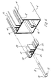
- the connecting part 20 is fixed to the bolt 2 by means of a coupling part 30 ( Fig. 4 ).
- the coupling part 30 has at its end a C-shaped section 31, wherein the lower leg 32 engages under the bottom of the connecting part 20.
- the coupling member 30 is preferably positively and non-positively inserted in the drainage groove 24 and 25 in the connecting part 20 and the bolt 2, wherein projections and prongs may be provided on the coupling member 30 to reinforce the frictional connection.
- the projections or serrations dig into the profile or into the drainage grooves 24 and 25.
- the coupling piece 30 can also be screwed.
- One or more coupling pieces 30 can be used.
- the attachment position is variable, for example, the coupling pieces 30 be arranged in the grooves 22 and 23 and on or in the retaining strip 20.
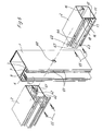
- a second embodiment is shown in which integrally formed on a connecting part 40 holding means.
- the connecting part 40 comprises an anchoring groove 45 and 49 at the edge and a retaining strip 47 in the middle. Between the retaining strip 47 and the groove 45, a drainage groove 46 is provided, while on the opposite side a drainage groove 48 is arranged.
- the profile of the connecting part 40 in turn corresponds to the profile of the bolt 2, wherein the respective grooves 45, 46, 48 and 49 are aligned with the grooves 10, 14, 15, 11 of the bolt 2.
- a plurality of web-shaped sections are provided, which abut at different points of the profile of the bolt 2.
- arms 44 and 43 are formed, which engage around the two walls of the retaining strip 13 laterally.
- a stop 51 is formed on the arm 43, and a corresponding stop is provided on the arm 44 so that the arms 43 and 44 rest positively on the end edge of the retaining strip 13 and thus fix the connecting part 40 in the lateral direction.
- the connecting part 40 In the latch 2 are frontally provided in the region of the grooves 10 and 11 recesses 17 and 18 into which a portion of the connecting part 40 can be inserted.
- bottom portions 41 and 42 are provided which engage under the grooves 10 and 11 partially.
- openings are recessed, so that the connecting part 40 can be fixed by means of screws 55 on the bolt 2, wherein the screws 55 pass through openings 19 in the grooves 10 and 11.
- a stop 50 is formed, which fits positively into the recess 18 of the web 11.
- the guided through the recesses 17 and 18 section serves as a coupling bridge to reach by means of the bottom webs 42 and 41 in the hollow profile of the bolt 2. There may be provided a plurality of such coupling bridges.
- the connecting part 40 can also be fixed to the bolt 2 by means of other types of fastening.
- a latch 2 is shown with a connecting part 40 in a transom-post construction.
- the connecting part 40 is laterally fixed by means of the arms 43 and 44 on the bolt 2, wherein a permanent fixing of the connecting part 40 follows by means of screws 55 which are screwed into the bolt 2 and the connecting part 40.
- a displaceable pin 61 is fixed to the mounting bar 16, which is inserted into an opening 60 on the post 1.
- a groove 62 is provided, which has approximately the same thickness as the wall of the post 1, so that the bolt 2 can be locked to the post 1.
- the connecting part 40 is additionally fixed by screws 55 to the post 1, wherein the screws 55 pass through the slots 53 and openings 63 within the groove 3 of the post 1.
- FIGs. 7A, 7B and 7C a third embodiment of the invention is shown, which is slightly modified compared to the second embodiment. However, the same components have been numbered with the same reference numerals.
- the connecting part 40 ' comprises portions 50' which engage in corresponding recesses in the grooves 10 and 11 of the bolt 2, wherein the portions 50 'are rounded at the end. Further, additional webs 80 and 81 are integrally formed on the connecting part 40 ', which engage in the drainage grooves 14 and 15 of the bolt 2. Otherwise, the connecting part 40 'corresponds to the connecting part 40.
- the connecting part 40' is fixed in height.
- the arms, which surround the retaining strip 13 a lateral fixation is provided.
- screws 55 are screwed into the connecting part 40 'here. Furthermore, screws 55 are screwed into the groove 3 of the post 1.
- a chamber 90 is provided below the drainage grooves 14 and 15 of the bolt 2 adjacent to the connecting part 40 ', which is surrounded on three sides by the connecting part 40' and abuts the post 1 on the open side here.
- sealing compound can be introduced into the chamber 90.
- a handset 70 is provided, is contained in the sealant. With this hand tool 70 can be filled in an opening 71 which is formed between the connecting part 40 'and the bolt 2, sealant in the chamber 90. As a result, the connection region between connection part 40 'and latch 2 can be securely sealed off.
- the hollow chamber 90 can also be filled with adhesive, to produce an adhesive bond with the bolt 2 with a corresponding design of the connecting part 40 '.
Landscapes
- Engineering & Computer Science (AREA)
- Architecture (AREA)
- Physics & Mathematics (AREA)
- Electromagnetism (AREA)
- Civil Engineering (AREA)
- Structural Engineering (AREA)
- Load-Bearing And Curtain Walls (AREA)
- Specific Sealing Or Ventilating Devices For Doors And Windows (AREA)
- Supports For Plants (AREA)
- Roof Covering Using Slabs Or Stiff Sheets (AREA)
- Mutual Connection Of Rods And Tubes (AREA)
- Conveying And Assembling Of Building Elements In Situ (AREA)
- Tents Or Canopies (AREA)
- Joining Of Corner Units Of Frames Or Wings (AREA)
Description
- Die vorliegende Erfindung betrifft eine Riegel-Pfosten-Konstruktion, insbesondere für Fassaden oder Lichtdächer, in deren Rahmenfelder Glasscheiben einfügbar sind, mit mehreren Pfosten, zwischen denen Riegel festgelegt sind, wobei die Pfosten an einer Außenfläche randseitig jeweils eine Nut zur Aufnahme einer Dichtung aufweisen und benachbart zu der Nut eine Drainage-Nut zur Ableitung von Flüssigkeit angeordnet ist, wobei der Riegel an der zur Außenfläche des Pfostens gewandten Seite randseitig jeweils eine Nut zur Aufnahme einer Dichtung und zwischen den Nuten eine Halteleiste aufweist.
- Aus der
DE 3419538 A1 ist eine Riegel-Pfosten-Konstruktion für eine Fassade oder ein Dach mit einem Metallrahmenwerk bekannt, in dessen Rahmenfelder Glasscheiben eingesetzt sind. Das Metallrahmenwerk umfasst Pfosten und sich quer dazu erstreckende Riegel, die jeweils randseitig eine Nut zur Aufnahme einer Dichtung aufweisen, um eine Glasscheibe randseitig umlaufend auf eine Dichtung abzulegen. Zur Festlegung der Glasscheibe sind Deckprofile vorgesehen, die mit entsprechenden Verankerungsnuten an den Riegeln und Pfosten verschraubt werden können. Zwischen den Verankerungsnuten und den Nuten zur Aufnahme der Dichtungen sind sowohl am Riegel als auch am Pfosten Drainage-Nuten vorgesehen, um Flüssigkeit, die zwischen der Verankerungsnut und der Glasscheibe am Riegel bzw. Pfosten eintritt, ableiten zu können. Der Riegel übergreift endseitig den Pfosten im Bereich der Nut zur Aufnahme der Dichtung und liegt daher etwas höher als der Pfosten. Dieser Höhenunterschied wird zum Glas hin durch unterschiedlich hohe Glasauflagedichtungen ausgeglichen, d. h. die Glasauflagedichtungen für die Riegel sind nicht so hoch wie die Glasauflagedichtungen für die Pfosten. Um diese Art der Verbindung zu realisieren, ist es erforderlich, dass das Riegelprofil im Endbereich ausgeklinkt wird. Diese Ausklinkung bedeutet einen erhöhten Arbeitsaufwand, da die Profile nicht einfach auf Länge gesägt werden können. Insbesondere bei langen Riegeln ist die Handhabung zum Ausklinken und die benötigte Maschinentechnik aufwendig. Ferner ergeben sich durch das Ausklinken erhöhte Toleranzen, da der Riegel zunächst abgesägt und anschließend ausgeklinkt wird, so dass die genaue Länge des Abschnittes des Riegels, der am Pfosten anliegt, durch den zusätzlichen Arbeitsschritt größeren Toleranzen unterliegt. - Weiter zeigt
US 5067293A eine Pfosten-Riegel Konstruktion nach Oberbegriff des Anspruch 1. - Es ist daher Aufgabe der vorliegenden Erfindung, eine Riegel-Pfosten-Konstruktion der eingangs genannten Art bereitzustellen, bei der die Montage der Riegel vereinfacht wird und ein nachteiliges Ausklinken des Riegels vermieden wird.
- Diese Aufgabe wird mit einer Riegel-Pfosten-Konstruktion mit den Merkmalen des Anspruches 1 gelöst.
- Wenn an dem Riegel stirnseitig ein Verbindungsteil angebracht ist, welches die Nuten und die Halteleiste des Riegels verlängert und zumindest teilweise die randseitige Nut des Pfostens überdeckt, wird zunächst die überlappende Bauweise beibehalten, wobei die Funktionen der Nuten und der Halteleiste des Riegels auch im randseitigen Bereich des Pfostens beibehalten werden. Insbesondere lässt sich mittels des Verbindungsteils anfallende Flüssigkeit in die Drainage-Nut des Pfostens ableiten. Die Montage des Riegels kann auf einfache Weise erfolgen, indem der Riegel auf die gewünschte Länge abgesägt wird. Anschließend wird er zwischen zwei Pfosten montiert, wobei das Verbindungsteil entweder vorher an dem Riegel oder anschließend an dem Riegel befestigt wird. Der Riegel ist dadurch mit geringen Toleranzen zwischen den Pfosten gehalten, da nur einmalig ein Absägen des Riegels erfolgt und nicht wie beim Stand der Technik, ein Ablängen des Riegels und nachfolgend ein Ausklinken des Riegels erforderlich ist. Zusätzlich erleichtert dies die Montage des Riegels, so dass die Mehrkosten durch das Verbindungsteil nicht negativ ins Gewicht fallen.
- Gemäß einer bevorzugten Ausführungsform der Erfindung ist das Verbindungsteil an dem Riegel festgelegt. Bei der Art der Festlegung ist der Fachmann grundsätzlich frei, da alle üblichen Befestigungsmethoden, wie Verschrauben, Verkleben, Verschweißen oder andere Verbindungstechniken möglich sind. Vorzugsweise wird jedoch eine mechanische Befestigung eingesetzt.
- Um eine einfach zu montierende und schnelle Befestigung des Verbindungsteils zu erreichen, ist dieses vorzugsweise an dem Riegel mittels eines Kopplungsteiles gehalten, das in eine hinterschnittene Nut am Riegel und am Verbindungsteil eingeschoben ist. Dabei kann das Kopplungsteil form- und kraftschlüssig in die Nut am Riegel eingefügt sein, so dass zumindest eine Vorfixierung des Kopplungsteiles gegeben ist. Insbesondere wenn das Kopplungsteil endseitig einen C-förmigen Abschnitt aufweist, der den Boden des Verbindungsteils umgreift, kann das Verbindungsteil auf einfache Weise benachbart zu dem Riegelprofil gehalten werden, ohne dass bei der Vormontage ein Werkzeug erforderlich ist. Damit der C-förmige Abschnitt die Auflage des Verbindungsteils am Pfosten nicht behindert, ist der am Boden des Verbindungsteils angeordnete Schenkel vorzugsweise in der randseitigen Drainage-Nut am Pfosten aufgenommen.
- Vorzugsweise weist der Riegel beidseitig der Halteleiste eine Drainage-Nut auf, in die jeweils ein Kopplungsteil eingefügt ist. Dabei können am Kopplungsteil auch Kanäle zur Ableitung von Flüssigkeit vorgesehen sein, um die Funktion der Drainage-Nut aufrechtzuerhalten.
- Gemäß einer weiteren Ausführungsform der Erfindung sind am Verbindungsteil Stege angeformt, die an dem Riegel anliegen. Vorzugsweise sind am dem Verbindungsteil Stege angeformt, die an den Nutwänden und/oder der Halteleiste des Riegels anliegen. Dadurch kann das Verbindungsteil ohne zusätzliches Bauteil an dem Riegel vorfixiert werden. Die Stege können formschlüssig an der Profiloberfläche des Riegels anliegen, so dass das Verbindungsteil allenfalls in Achsrichtung des Riegels bewegbar ist.
- Um eine besonders stabile Befestigung des Verbindungsteils mittels Stegen zu erhalten, ist stirnseitig an dem Riegel mindestens eine Aussparung vorgesehen, durch die ein Steg des Verbindungsteils eingeführt ist. Dadurch kann ein Steg unterhalb des Nutbodens bzw. des Bodens der Halteleiste greifen, um eine flächige Abstützung des Verbindungsteils zu ermöglichen.
- Gemäß einer weiteren Ausführungsform der Erfindung ist unterhalb des Verbindungsteils eine Hohlkammer ausgebildet, in die eine Versiegelungsmasse zur Abdichtung einer an dem Riegel und dem Verbindungsteil gebildeten Drainage-Nut einfügbar ist. Durch den Einsatz eines zusätzlichen Bauteils im Bereich des Übergangs zwischen Riegel und Pfosten können Spalte entstehen, in denen sich Flüssigkeit ansammeln kann. Um dies zu vermeiden, sind diese Spalte vorzugsweise mittels einer Versiegelungs- oder Klebermasse abgedichtet. Die Versiegelungsmasse wird vorzugsweise durch eine am Übergang zwischen Riegel und Verbindungsteil gebildete Öffnung eingebracht.
- Um die mechanische Festlegung des Verbindungsteils dauerhaft zu gewährleisten, ist vorzugsweise das Verbindungsstück mit der randseitigen Nut am Pfosten verschraubt.
- Die Erfindung wird nachfolgend anhand von drei Ausführungsbeispielen anhand der beigefügten Zeichnungen näher erläutert. Es zeigen:
- Fig. 1
- eine perspektivische Ansicht eines ersten Ausführungsbeispiels einer erfindungsgemäßen Riegel-Pfosten-Konstruktion;
- Fig. 2
- eine schematische Schnittansicht der Riegel-Pfosten-Konstruktion der
Fig. 1 ; - Fig. 3
- eine perspektivische Ansicht des Riegels und des Verbindungsteils der Riegel-Pfosten-Konstruktion der
Fig. 1 ; - Fig. 4
- eine perspektivische Ansicht des Riegels und des Verbindungsteils gemäß
Fig. 3 mit einem Kopplungsteil; - Fig. 5
- eine perspektivische Ansicht eines Riegels mit einem Verbindungsteil gemäß einem zweiten Ausführungsbeispiel der vorliegenden Erfindung;
- Fig. 6
- eine perspektivische Ansicht der Riegel-Pfosten-Konstruktion gemäß dem zweiten Ausführungsbeispiel;
- Fig. 7A
- eine Seitenansicht der Riegel-Pfosten-Konstruktion gemäß einem dritten Ausführungsbeispiel;
- Fig. 7B
- eine teilweise geschnittene Draufsicht auf die Riegel-Pfosten-Konstruktion gemäß
Fig. 7A , und - Fig. 7C
- eine stirnseitige Ansicht auf den Riegel gemäß der Riegel-Pfosten-Konstruktion nach
Fig. 7A . - Wie in den
Fig. 1 und2 gezeigt ist, umfasst die Riegel-Pfosten-Konstruktion einen vertikalen Pfosten 1, an dem sich rechtwinklig ein Riegel 2 anschließt. Es ist allerdings auch möglich, den Riegel 2 in einem anderen Winkel an dem Pfosten 1 anzuschließen. An dem Pfosten 1 sind randseitig Nuten 3 und 4 zur Aufnahme einer Glasauflagedichtung vorgesehen. Benachbart zu der Nut 3 ist eine Drainage-Nut 7 vorgesehen, durch die eine Flüssigkeit nach unten abgeleitet werden kann. Auch auf der gegenüberliegenden Seite ist eine Drainage-Nut 8 vorgesehen. Mittig umfasst der Pfosten 1 eine Verankerungsleiste 9, in die ein Montageelement 102 einfügbar ist. Wie inFig. 2 zu sehen ist, können Glasscheiben 100 in die durch Pfosten 1 und Riegel 2 gebildeten Felder eingefügt werden, wobei diese dann auf den Glasauflagedichtungen 5, 6 und 12 aufliegen. Die Glasscheiben 100 werden mittels nicht dargestellten Deckleisten an dem Montageelement 102 und somit an dem Pfosten 1 und dem Riegel 2 festgelegt. - In
Fig. 2 sind schematisch einzelne Tröpfchen dargestellt, die den Eintritt von Feuchtigkeit zwischen Glasscheibe 100 und der Drainage-Nut 14 des Riegels 2 darstellen sollen. Die Feuchtigkeit wird über die Drainage-Nuten 14 und 15 am Riegel 2 zu der Drainage-Nut 7 am Pfosten 1 abgeleitet und aus der Riegel-Pfosten-Konstruktion abgeleitet. Die Glasscheiben 100 sind hiervon nicht berührt, da diese auf den Glasauflagedichtungen 5 und 12 aufliegen, wobei der Höhenunterschied zum Glas hin durch unterschiedlich hohe Glasauflagedichtungen 5 bzw. 12 ausgeglichen wird. - An dem Riegel 2 ist mittig eine Halteleiste 13 vorgesehen, die beidseitig von Drainage-Nuten 14 und 15 umgeben ist.
- Wie insbesondere in
Fig. 3 erkennbar ist, ist der überlappende Bereich benachbart zu der Nut 3 des Pfostens 1 durch ein Verbindungsteil 20 gebildet, das getrennt von dem Riegel 2 ausgebildet ist und an diesem festgelegt ist. Das Verbindungsteil 20 umfasst Verankerungsnuten 22 und 23 für jeweils eine Glasauflagedichtung, die mit den Verankerungsnuten 10 und 11 des Riegels 2 fluchten. Ebenso sind an dem Verbindungsteil 20 Drainage-Nuten 24 und 25 ausgebildet, die mit den Drainage-Nuten 14 und 15 des Riegels 2 fluchten. Die Profilierung des Verbindungsteils 20 entspricht der Profilierung an der Außenfläche des Riegels 2. An dem Riegel 2 ist ferner noch eine Befestigungsleiste 16 vorgesehen, um den Riegel 2 an dem Pfosten 1 sicher festlegen zu können. - Gemäß der ersten Ausführungsform der Erfindung wird das Verbindungsteil 20 mittels eines Kopplungsteiles 30 an dem Riegel 2 festgelegt (
Fig. 4 ). Das Kopplungsteil 30 umfasst endseitig einen C-förmigen Abschnitt 31, wobei der untere Schenkel 32 den Boden des Verbindungsteils 20 untergreift. Das Kopplungsteil 30 ist vorzugsweise form- und kraftschlüssig in der Drainage-Nut 24 bzw. 25 in dem Verbindungsteil 20 und dem Riegel 2 eingefügt, wobei zur Verstärkung des Kraftschlusses auch Vorsprünge oder Zacken an dem Kopplungsteil 30 vorgesehen sein können. Die Vorsprünge bzw. Zacken graben sich in das Profil bzw. in die Drainage-Nuten 24 und 25 ein. Das Kopplungsstück 30 kann auch verschraubt werden. Es können ein oder mehrere Kopplungsstücke 30 zum Einsatz kommen. Auch ist die Befestigungsposition variabel, beispielsweise können die Kopplungsstücke 30 auch in den Nuten 22 und 23 sowie an oder in der Halteleiste 20 angeordnet werden. - In
Fig. 5 ist eine zweite Ausführungsform gezeigt, bei der an einem Verbindungsteil 40 integral Haltemittel ausgebildet sind. Das Verbindungsteil 40 umfasst randseitig jeweils eine Verankerungsnut 45 und 49 und mittig eine Halteleiste 47. Zwischen der Halteleiste 47 und der Nut 45 ist eine Drainage-Nut 46 vorgesehen, während auf der gegenüberliegenden Seite eine Drainage-Nut 48 angeordnet ist. Das Profil des Verbindungsteils 40 entspricht wiederum dem Profil des Riegels 2, wobei die jeweiligen Nuten 45, 46, 48 und 49 mit den Nuten 10, 14, 15, 11 des Riegels 2 fluchten. - Zur Vorfixierung des Halteteils 40 sind mehrere stegförmige Abschnitte vorgesehen, die an verschiedenen Stellen des Profils des Riegels 2 anliegen. An der Halteleiste 47 sind Arme 44 und 43 ausgebildet, die die beiden Wände der Halteleiste 13 seitlich umgreifen. Am Arm 43 ist ein Anschlag 51 ausgebildet, und am Arm 44 ist ein entsprechender Anschlag vorgesehen, so dass die Arme 43 und 44 formschlüssig an der Stirnkante der Halteleiste 13 anliegen und somit das Verbindungsteil 40 in seitlicher Richtung fixieren.
- In dem Riegel 2 sind stirnseitig im Bereich der Nuten 10 und 11 Aussparungen 17 und 18 vorgesehen, in die ein Abschnitt des Verbindungsteils 40 einfügbar ist. An dem Verbindungsteil 40 sind Bodenabschnitte 41 und 42 vorgesehen, die die Nuten 10 und 11 teilweise untergreifen. In den Bodenstegen 41 und 42 sind Öffnungen ausgespart, so dass das Verbindungsteil 40 mittels Schrauben 55 an dem Riegel 2 festgelegt werden kann, wobei die Schrauben 55 Öffnungen 19 in den Nuten 10 und 11 durchgreifen. An dem Bodensteg 42 ist ein Anschlag 50 ausgebildet, der formschlüssig in die Aussparung 18 des Steges 11 passt. Der durch die Aussparungen 17 und 18 geführte Abschnitt dient als Kopplungsbrücke, um mittels den Bodenstegen 42 und 41 in das Hohlprofil des Riegels 2 zu gelangen. Es können mehrere solcher Kopplungsbrücken vorgesehen sein. Ferner kann das Verbindungsteil 40 auch mittels anderer Befestigungsarten an dem Riegel 2 festgelegt werden.
- In dem Verbindungsteil 40 sind Langlöcher 53 vorgesehen, um das Verbindungsteil 40 mit dem Pfosten 1 verschrauben zu können.
- In
Fig. 6 ist ein Riegel 2 mit einem Verbindungsteil 40 in einer Riegel-Pfosten-Konstruktion dargestellt. Das Verbindungsteil 40 ist mittels der Arme 43 und 44 seitlich an dem Riegel 2 fixiert, wobei eine dauerhafte Festlegung des Verbindungsteils 40 über Schrauben 55 folgt, die in den Riegel 2 und das Verbindungsteil 40 eingeschraubt sind. Zur Lastabtragung großer Kräfte ist an der Befestigungsleiste 16 ein verschiebbarer Zapfen 61 festgelegt, der in eine Öffnung 60 am Pfosten 1 eingefügt wird. An dem Zapfen 61 ist eine Rille 62 vorgesehen, die etwa dieselbe Dicke besitzt wie die Wand des Pfostens 1, so dass der Riegel 2 mit dem Pfosten 1 verrastbar ist. Das Verbindungsteil 40 ist mittels Schrauben 55 zusätzlich an dem Pfosten 1 festgelegt, wobei die Schrauben 55 die Langlöcher 53 und Öffnungen 63 innerhalb der Nut 3 des Pfostens 1 durchgreifen. - In den
Fig. 7A, 7B und 7C ist eine dritte Ausführungsform der Erfindung dargestellt, die gegenüber dem zweiten Ausführungsbeispiel leicht modifiziert ist. Gleiche Bauteile sind jedoch mit gleichen Bezugszeichen beziffert worden. - Das Verbindungsteil 40' umfasst Abschnitte 50', die in entsprechende Ausnehmungen in den Nuten 10 und 11 des Riegels 2 greifen, wobei die Abschnitte 50' stirnseitig gerundet sind. Ferner sind an dem Verbindungsteil 40' zusätzliche Stege 80 und 81 angeformt, die in die Drainage-Nuten 14 und 15 des Riegels 2 eingreifen. Ansonsten entspricht das Verbindungsteil 40' dem Verbindungsteil 40. Durch die Bodenstege 41 und 42 sowie die Stege 80 und 81 ist das Verbindungsteil 40' in der Höhe fixiert. Durch die Arme, die die Halteleiste 13 umgreifen ist eine seitliche Fixierung vorgesehen. Zur mechanischen Festlegung sind auch hier Schrauben 55 in das Verbindungsteil 40' eingeschraubt. Ferner sind Schrauben 55 in die Nut 3 des Pfostens 1 eingeschraubt.
- Wie insbesondere aus
Fig. 7C ersichtlich ist, ist unterhalb der Drainage-Nuten 14 und 15 des Riegels 2 benachbart zu dem Verbindungsteil 40' eine Kammer 90 vorgesehen, die an drei Seiten von dem Verbindungsteil 40' umgeben ist und an der hier offenen Seite am Pfosten 1 anliegt. Um den Übergangsbereich zwischen dem Riegel 2 und dem Pfosten 1, insbesondere auch im Bereich der Drainage-Nuten 14 und 15 abzudichten, kann in die Kammer 90 Versiegelungsmasse eingefüllt werden. Hierzu ist ein Handgerät 70 vorgesehen, in dem Versiegelungsmasse enthalten ist. Mit diesem Handgerät 70 lässt sich in eine Öffnung 71, die zwischen dem Verbindungsteil 40' und dem Riegel 2 gebildet ist, Versiegelungsmasse in die Kammer 90 einfüllen. Dadurch lässt sich der Verbindungsbereich zwischen Verbindungsteil 40' und Riegel 2 sicher abdichten. Die Hohlkammer 90 kann ferner auch mit Kleber gefüllt werden, um bei entsprechender Ausbildung des Verbindungsteiles 40' eine Klebverbindung mit dem Riegel 2 herzustellen.
Claims (13)
- Riegel-Pfosten-Konstruktion, insbesondere für Fassaden oder Lichtdächer, in deren Rahmenfelder Glasscheiben (100) einfügbar sind, mit mehreren Pfosten (1), zwischen denen Riegel (2) festgelegt sind, wobei die Pfosten (1) an einer Außenfläche randseitig jeweils eine Nut (3, 4) zur Aufnahme einer Dichtung (5, 6) aufweisen und benachbart zu den Nuten (3, 4) eine Drainage-Nut (7, 8) zur Ableitung von Flüssigkeit angeordnet ist, wobei der Riegel (2) an der zur Außenfläche des Pfostens (1) gewandten Seite randseitig jeweils eine Nut (10, 11) zur Aufnahme einer Dichtung (12) und zwischen den Nuten (10, 11) eine Halteleiste (13) aufweist, dadurch gekennzeichnet, dass an dem Riegel (2) stirnseitig ein Verbindungsteil (20, 40, 40') angebracht ist, welches die Nuten (10, 11) und die Halteleiste (13) des Riegels (2) verlängert und zumindest teilweise die randseitige Nut (3) des Pfostens (1) überdeckt.
- Riegel-Pfosten-Konstruktion nach Anspruch 1, dadurch gekennzeichnet, dass das Verbindungsteil (20, 40 40') an dem Riegel (2) festgelegt ist.
- Riegel-Pfosten-Konstruktion nach Anspruch 1 oder 2, dadurch gekennzeichnet, dass das Verbindungsteil (20) an dem Riegel (2) mittels eines Kopplungsteiles (30) gehalten ist, das in eine hinterschnittene Nut (14, 15, 24, 25) am Riegel (2) und am Verbindungsteil (20) eingeschoben ist.
- Riegel-Pfosten-Konstruktion nach einem der Ansprüche 1 bis 3, dadurch gekennzeichnet, dass das Kopplungsteil (30) form- und kraftschlüssig in die Nut (14, 15) am Riegel (2) eingefügt ist.
- Riegel-Pfosten-Konstruktion nach Anspruch 3 oder 4, dadurch gekennzeichnet, dass das Kopplungsteil (30) endseitig einen C-förmigen Abschnitt (31) aufweist, der den Boden des Verbindungsteiles (20) umgreift.
- Riegel-Pfosten-Konstruktion nach Anspruch 5, dadurch gekennzeichnet, dass der unter dem Boden des Verbindungsteils (20) angeordnete Schenkel (32) des C-förmigen Abschnittes (31) in der randseitigen Drainage-Nut (7) am Pfosten (1) aufgenommen ist.
- Riegel-Pfosten-Konstruktion nach einem der Ansprüche 1 bis 6, dadurch gekennzeichnet, dass der Riegel (2) beidseitig der Halteleiste (13) eine Drainage-Nut (14, 15) aufweist, in die jeweils ein Kopplungsteil (30) eingefügt ist.
- Riegel-Pfosten-Konstruktion nach einem der Ansprüche 1 bis 7, dadurch gekennzeichnet, dass am Verbindungsteil (40, 40') Stege (41, 42, 43, 44, 80, 81) angeformt sind, die an dem Riegel (2) anliegen.
- Riegel-Pfosten-Konstruktion nach einem der Ansprüche 1 bis 8, dadurch gekennzeichnet, dass an dem Verbindungsteil (40, 40') Stege (43, 44, 80, 81) angeformt sind, die an den Nutwänden und/oder der Halteleiste (13) des Riegels (2) anliegen.
- Riegel-Pfosten-Konstruktion nach Anspruch 8 oder 9, dadurch gekennzeichnet, dass am Verbindungsteil (40, 40') mindestens ein Steg (41, 42) angeformt ist, der die Außenfläche des Riegels (2) untergreift.
- Riegel-Pfosten-Konstruktion nach einem der Ansprüche 1 bis 10, dadurch gekennzeichnet, dass stirnseitig an dem Riegel (2) mindestens eine Aussparung vorgesehen ist, durch die ein Steg (41, 42) des Verbindungsteils (40, 40') geführt ist.
- Riegel-Pfosten-Konstruktion nach einem der Ansprüche 1 bis 11, dadurch gekennzeichnet, dass unterhalb des Verbindungsteils (40, 40') eine Hohlkammer (90) ausgebildet ist, in die eine Versiegelungsmasse zur Abdichtung einer an dem Riegel (2) und dem Verbindungsteil (40,40') gebildeten Drainage-Nut (14, 15, 46, 48) einfügbar ist.
- Riegel-Pfosten-Konstruktion nach einem der Ansprüche 1 bis 12, dadurch gekennzeichnet, dass das Verbindungsstück (40, 40') mit der randseitigen Nut (3) am Pfosten (1) verschraubt ist.
Applications Claiming Priority (3)
| Application Number | Priority Date | Filing Date | Title |
|---|---|---|---|
| DE10101720A DE10101720A1 (de) | 2001-01-15 | 2001-01-15 | Riegel-Pfosten-Konstruktion |
| DE10101720 | 2001-01-15 | ||
| PCT/EP2002/000176 WO2002055803A1 (de) | 2001-01-15 | 2002-01-10 | Riegel-pfosten-konstruktion |
Publications (2)
| Publication Number | Publication Date |
|---|---|
| EP1352134A1 EP1352134A1 (de) | 2003-10-15 |
| EP1352134B1 true EP1352134B1 (de) | 2010-02-24 |
Family
ID=7670693
Family Applications (1)
| Application Number | Title | Priority Date | Filing Date |
|---|---|---|---|
| EP02702252A Expired - Lifetime EP1352134B1 (de) | 2001-01-15 | 2002-01-10 | Riegel-pfosten-konstruktion |
Country Status (14)
| Country | Link |
|---|---|
| US (1) | US7080488B2 (de) |
| EP (1) | EP1352134B1 (de) |
| CN (1) | CN1233911C (de) |
| AT (1) | ATE458873T1 (de) |
| CA (1) | CA2430058C (de) |
| DE (2) | DE10101720A1 (de) |
| EA (1) | EA004638B1 (de) |
| HR (1) | HRP20030537B1 (de) |
| HU (1) | HUP0500792A2 (de) |
| NO (1) | NO20033195L (de) |
| PL (1) | PL212133B1 (de) |
| RS (1) | RS50321B (de) |
| UA (1) | UA75115C2 (de) |
| WO (1) | WO2002055803A1 (de) |
Cited By (1)
| Publication number | Priority date | Publication date | Assignee | Title |
|---|---|---|---|---|
| DE202013104191U1 (de) * | 2013-09-13 | 2014-12-16 | SCHÜCO International KG | Pfosten-Riegel-Konstruktion |
Families Citing this family (36)
| Publication number | Priority date | Publication date | Assignee | Title |
|---|---|---|---|---|
| DE20021878U1 (de) * | 2000-12-29 | 2001-06-07 | Schüco International KG, 33609 Bielefeld | Fassade und/oder Dach mit Dichtungsleiste mit Füllstück |
| AU2002353528A1 (en) * | 2002-11-08 | 2004-06-07 | Alprogetti S.R.L. | System for joining mullions to transoms by frontal link |
| DE10255223A1 (de) * | 2002-11-27 | 2004-06-17 | Wicona Bausysteme Gmbh | Gebäudefassade oder Dach |
| US7818931B2 (en) * | 2004-06-01 | 2010-10-26 | Oldcastle Glass Engineered Products, Inc. | Curtain wall external support system |
| US9101927B2 (en) | 2005-01-31 | 2015-08-11 | Realbio Technologies Ltd. | Multistep reaction lateral flow capillary device |
| US7779584B2 (en) * | 2005-03-08 | 2010-08-24 | Muridal Inc. | Curtain wall system |
| ITTV20060011A1 (it) * | 2006-02-03 | 2007-08-04 | Permasteelisa Spa | Struttura di pannello, particolarmente per la realizzazione di facciate strutturali resistenti alle esplosioni. |
| GB2444257B (en) * | 2006-11-29 | 2010-03-10 | Levolux At Ltd | Improvements in or relating to curtain walling |
| US9151056B2 (en) * | 2008-04-17 | 2015-10-06 | Konvin Associates, L.P. | Dual glazing panel system |
| DE102008037964A1 (de) * | 2008-08-13 | 2010-02-25 | Solon Se | Montagevorrichtung für Solarmodule mit einem großen Aspektverhältnis |
| US8266851B2 (en) * | 2009-02-03 | 2012-09-18 | Ply Gem Industries, Inc. | Mullion system |
| CA2724952A1 (en) * | 2009-12-11 | 2011-06-11 | Groupe Lessard Inc. | System and method for refurbishing an existing curtain wall |
| CA2816346C (en) * | 2010-06-04 | 2018-06-12 | Milgard Manufacturing Incorporated | Window mull system |
| DE102010049160B9 (de) * | 2010-10-22 | 2012-10-25 | Werner Schmitz | Dichtstück |
| FI123260B (fi) * | 2010-12-15 | 2013-01-15 | Picote Oy Ltd | Vesieristysjärjestely ja menetelmä |
| US9163400B2 (en) | 2011-02-23 | 2015-10-20 | Oldcastle Buildingenvelope, Inc. | Method and system for improved curtain wall sealing |
| USD666309S1 (en) * | 2011-09-21 | 2012-08-28 | Shenyang Yuanda Aluminium Industry Engineering Co., Ltd. | Main mullion for curtain wall connection |
| USD666312S1 (en) * | 2011-09-21 | 2012-08-28 | Shenyang Yuanda Aluminium Industry Engineering Co., Ltd. | Lower transom of curtain wall |
| USD666310S1 (en) * | 2011-09-21 | 2012-08-28 | Shenyang Yuanda Aluminium Industry Engineering Co., Ltd. | Assisting mullion for curtain wall connection |
| USD666311S1 (en) * | 2011-09-21 | 2012-08-28 | Shenyang Yuanda Aluminium Industry Engineering Co., Ltd. | Upper transom of curtain wall |
| DE202011108996U1 (de) * | 2011-12-12 | 2013-03-13 | Raico Bautechnik Gmbh | Dichtungsanordnung für Fenster, Türen und Fassaden |
| CN103938771B (zh) * | 2014-03-26 | 2016-08-31 | 安徽盛达前亮铝业有限公司 | 隐框幕墙卡槽式横梁 |
| DE102015100524A1 (de) * | 2015-01-14 | 2016-07-14 | SCHÜCO International KG | Pfosten-Riegel-Konstruktion |
| CN104912240A (zh) * | 2015-06-24 | 2015-09-16 | 上海美特幕墙有限公司 | 单元式幕墙系统中的干法密封组件及其制造方法 |
| US9567746B1 (en) * | 2015-10-15 | 2017-02-14 | Arconic Inc. | Curtain wall system with anti-rolling shear block |
| CN105297975A (zh) * | 2015-10-30 | 2016-02-03 | 成都格瑞思文化传播有限公司 | 幕墙横梁整体结构 |
| CN105781032A (zh) * | 2016-03-25 | 2016-07-20 | 中国建筑第二工程局有限公司 | 一种阳光板开启天窗无损导水腔独立排水安全窗框 |
| BE1024285B1 (nl) * | 2016-05-24 | 2018-01-15 | Claeys Stephanie Catharina R. | Gordijngevel en set en werkwijze voor het opbouwen van een dergelijke gordijngevel |
| BE1024681B1 (nl) * | 2016-10-21 | 2018-05-22 | Claeys Stephanie Catharina R. | Gordijngevel met gevelelementen met een tweedelig kader voor een vleugel of dergelijke en werkwijze voor het vervangen van een opvulelement in een gordijngevel. |
| US10309150B2 (en) * | 2017-09-14 | 2019-06-04 | Arconic Inc. | Structural glazing weather seal with captured glazing option |
| DE102017223873A1 (de) * | 2017-12-29 | 2019-07-04 | Ingo Kneer | Überdachungsvorrichtung |
| US10889986B1 (en) * | 2019-09-03 | 2021-01-12 | Plyco Corporation | CUPOLA body fabricated from extrusions |
| CN112160476B (zh) * | 2020-10-12 | 2021-10-26 | 台州技创机械科技有限公司 | 一种幕墙梁柱连接结构和施工方法 |
| CN112343225A (zh) * | 2020-11-04 | 2021-02-09 | 安徽锐利玻璃机械有限公司 | 一种玻璃固定用梁组件结构 |
| US12371903B2 (en) * | 2020-12-18 | 2025-07-29 | Arconic Technologies Llc | Curtain wall system accommodating wiring |
| US12188223B2 (en) * | 2021-06-08 | 2025-01-07 | Permasteelisa North America Corp. | Curtain wall and drainage cavity for curtain wall unit |
Family Cites Families (18)
| Publication number | Priority date | Publication date | Assignee | Title |
|---|---|---|---|---|
| DE3203625A1 (de) * | 1982-02-03 | 1983-08-11 | Trube & Kings KG, 5000 Köln | Bauteil wie gebaeudefassaden und dergleichen |
| US4638613A (en) * | 1984-05-25 | 1987-01-27 | Schuco Heinz Schurmann Gmbh & Co. | Metal-glass structure for a front wall or a roof |
| DE3419538A1 (de) | 1984-05-25 | 1985-11-28 | SCHÜCO Heinz Schürmann GmbH & Co, 4800 Bielefeld | Fassade oder dach in einer metall-glas-ausfuehrung |
| DE3502476A1 (de) * | 1985-01-25 | 1986-08-07 | Julius & August Erbslöh GmbH + Co, 5620 Velbert | Verbinder zum anschluss von tragprofilen an standprofilen, insbesondere zur bildung von fassaden-gitterwerken |
| US4686805A (en) * | 1985-02-21 | 1987-08-18 | Jarl Extrusions, Inc. | Panel support |
| US4650702A (en) * | 1985-10-15 | 1987-03-17 | Kawneer Company, Inc. | Structural interface and weatherseal for structurally bonded glazing |
| GB2222195B (en) * | 1988-08-13 | 1992-06-17 | Hempsted Patent Glazing Co Ltd | Glazing systems |
| US4974385A (en) * | 1989-05-11 | 1990-12-04 | Naturalite/Epi, Inc. | Purlin and rafter interconnection system |
| GB2234992A (en) * | 1989-08-16 | 1991-02-20 | Don Reynolds Limited | Expansion joint in curtain walling |
| US5245808A (en) * | 1989-12-01 | 1993-09-21 | Kawneer Company, Inc. | Retainer and weatherseal for structurally bonded glazing |
| CA2050052C (en) * | 1991-07-16 | 2003-12-23 | Wayne E. Whitmyer | Last lite retainer and weather seal for structurally bonded glazing |
| DE4125976A1 (de) * | 1991-08-06 | 1993-02-11 | Philippi Gerd | Profilverbindung, insbesondere fuer aluminium-leichtbau |
| US5369924A (en) * | 1993-04-30 | 1994-12-06 | Neudorf; Peter | Structural curtainwall system and components therefor |
| SE507517C2 (sv) * | 1996-10-17 | 1998-06-15 | Flaekt Ab | Balkkonstruktion för tak i rena rum |
| DE19700696B4 (de) * | 1997-01-13 | 2008-07-31 | SCHÜCO International KG | Fassade oder Glasdach in Brandschutzausführung |
| JPH10237998A (ja) * | 1997-02-26 | 1998-09-08 | Ykk Architect Prod Kk | 方立式カーテンウォール |
| FR2764362B1 (fr) * | 1997-06-10 | 1999-08-06 | Alcan France | Dispositif d'etancheite pour l'assemblage de deux profiles metalliques |
| DE19901775A1 (de) * | 1999-01-18 | 2000-07-20 | Schueco Int Kg | T-Verbindung zwischen einem Sprossen- und einem Pfostenprofil einer Fassade oder eines Lichtdaches |
-
2001
- 2001-01-15 DE DE10101720A patent/DE10101720A1/de not_active Ceased
-
2002
- 2002-01-10 EA EA200300790A patent/EA004638B1/ru not_active IP Right Cessation
- 2002-01-10 CA CA002430058A patent/CA2430058C/en not_active Expired - Fee Related
- 2002-01-10 EP EP02702252A patent/EP1352134B1/de not_active Expired - Lifetime
- 2002-01-10 CN CN02803301.9A patent/CN1233911C/zh not_active Expired - Fee Related
- 2002-01-10 HR HR20030537A patent/HRP20030537B1/xx not_active IP Right Cessation
- 2002-01-10 AT AT02702252T patent/ATE458873T1/de active
- 2002-01-10 WO PCT/EP2002/000176 patent/WO2002055803A1/de not_active Ceased
- 2002-01-10 PL PL363579A patent/PL212133B1/pl unknown
- 2002-01-10 HU HU0500792A patent/HUP0500792A2/hu unknown
- 2002-01-10 RS YUP-547/03A patent/RS50321B/sr unknown
- 2002-01-10 US US10/433,184 patent/US7080488B2/en not_active Expired - Fee Related
- 2002-01-10 DE DE50214230T patent/DE50214230D1/de not_active Expired - Lifetime
- 2002-10-01 UA UA2003087746A patent/UA75115C2/uk unknown
-
2003
- 2003-07-14 NO NO20033195A patent/NO20033195L/no unknown
Cited By (1)
| Publication number | Priority date | Publication date | Assignee | Title |
|---|---|---|---|---|
| DE202013104191U1 (de) * | 2013-09-13 | 2014-12-16 | SCHÜCO International KG | Pfosten-Riegel-Konstruktion |
Also Published As
| Publication number | Publication date |
|---|---|
| DE10101720A1 (de) | 2002-07-18 |
| DE50214230D1 (de) | 2010-04-08 |
| PL212133B1 (pl) | 2012-08-31 |
| YU54703A (sh) | 2006-03-03 |
| CA2430058A1 (en) | 2002-07-18 |
| CN1233911C (zh) | 2005-12-28 |
| EP1352134A1 (de) | 2003-10-15 |
| NO20033195D0 (no) | 2003-07-14 |
| CA2430058C (en) | 2010-03-02 |
| EA200300790A1 (ru) | 2003-12-25 |
| HUP0500792A2 (hu) | 2005-12-28 |
| ATE458873T1 (de) | 2010-03-15 |
| US20040031220A1 (en) | 2004-02-19 |
| RS50321B (sr) | 2009-09-08 |
| WO2002055803A1 (de) | 2002-07-18 |
| HRP20030537A2 (en) | 2005-06-30 |
| NO20033195L (no) | 2003-07-14 |
| PL363579A1 (en) | 2004-11-29 |
| HK1063831A1 (en) | 2005-01-14 |
| US7080488B2 (en) | 2006-07-25 |
| UA75115C2 (en) | 2006-03-15 |
| CN1479830A (zh) | 2004-03-03 |
| EA004638B1 (ru) | 2004-06-24 |
| HRP20030537B1 (en) | 2011-02-28 |
Similar Documents
| Publication | Publication Date | Title |
|---|---|---|
| EP1352134A1 (de) | Riegel-pfosten-konstruktion | |
| DE3419538C2 (de) | ||
| EP1020575B1 (de) | T-Verbindung zwischen einem Sprossen- und einem Pfostenprofil einer Fasade oder eines Lichtdaches | |
| EP0436869A2 (de) | Verbindung des Stosses zwischen Riegel und Pfosten an einem Traggerippe für eine oder an einer Fassadenwand | |
| EP1223257B1 (de) | Riegel/Pfosten-Konstruktion | |
| DE19849152A1 (de) | Pfosten-Riegelverbindung | |
| DE4331963C2 (de) | Anordnung zur lösbaren Befestigung von vorzugsweise ebenen Elementen in einem von Pfosten und Riegeln gebildeten System | |
| EP0821127A2 (de) | Vorrichtung zur thermisch isolierten Befestigung von flachen Bauelementen | |
| EP1840314B1 (de) | Bauelement in Brandschutzausführung | |
| DE19828382C2 (de) | Anordnung zum Befestigen eines einen Hohlquerschnitt aufweisenden Pfostens am Blendrahmen eines Fensters oder einer Türe aus Kunststoff oder Leichtmetall | |
| EP1346114B1 (de) | Fassade und/oder dach | |
| EP1098046B1 (de) | Verkleidungssystem für Fassaden und Dächer von Bauwerken | |
| EP2186959B1 (de) | T-Verbindung zwischen einem Pfosten- und Riegelprofil | |
| EP1020576B1 (de) | Fassade oder Lichtdach mit einem Rahmenwerk aus Pfosten- und Sprossenprofilen | |
| EP3879043B1 (de) | Dichtstück zur abdichtung einer t-verbindung zwischen einem pfosten- und riegelprofil und pfosten-riegel-konstruktion mit einem derartigen dichtstück | |
| DE29501568U1 (de) | Verbindungselement | |
| EP2055886A2 (de) | Mechanischer Verbinder | |
| EP1826331A2 (de) | Montagehilfe und Pfosten-Riegel-Konstruktion | |
| EP1836359A1 (de) | Modulare fassade für gebäude, glasauflagedichtung und schraube | |
| DE2750351A1 (de) | Profilkonstruktion | |
| EP3907340B1 (de) | Dichtungsprofil und pfosten-riegel-konstruktion | |
| DE2553801A1 (de) | Rahmenkonstruktion fuer tueren, fenster u.dgl. | |
| DE102020106891B4 (de) | T-Verbindung zwischen einem Pfosten- und Riegelprofil und Pfosten-Riegel-Konstruktion mit einer derartigen T-Verbindung | |
| DE3936727C2 (de) | Profil für einen Rahmenschenkel oder eine Sprosse | |
| EP4361369A1 (de) | Fassadenkonstruktion und verfahren zur montage einer fassadenkonstruktion |
Legal Events
| Date | Code | Title | Description |
|---|---|---|---|
| PUAI | Public reference made under article 153(3) epc to a published international application that has entered the european phase |
Free format text: ORIGINAL CODE: 0009012 |
|
| 17P | Request for examination filed |
Effective date: 20030502 |
|
| AK | Designated contracting states |
Kind code of ref document: A1 Designated state(s): AT BE CH CY DE DK ES FI FR GB GR IE IT LI LU MC NL PT SE TR |
|
| AX | Request for extension of the european patent |
Extension state: AL LT LV MK RO SI |
|
| RIN1 | Information on inventor provided before grant (corrected) |
Inventor name: PROUST, BERNARD Inventor name: HAMDINE, MOHAMMED Inventor name: HOECKER, EITEL-FRIEDRICH |
|
| GRAP | Despatch of communication of intention to grant a patent |
Free format text: ORIGINAL CODE: EPIDOSNIGR1 |
|
| RIN1 | Information on inventor provided before grant (corrected) |
Inventor name: PROUST, BERNARD Inventor name: HAMDINE, MOHAMMED Inventor name: HOECKER, EITEL-FRIEDRICH |
|
| GRAS | Grant fee paid |
Free format text: ORIGINAL CODE: EPIDOSNIGR3 |
|
| GRAA | (expected) grant |
Free format text: ORIGINAL CODE: 0009210 |
|
| AK | Designated contracting states |
Kind code of ref document: B1 Designated state(s): AT BE CH CY DE DK ES FI FR GB GR IE IT LI LU MC NL PT SE TR |
|
| AX | Request for extension of the european patent |
Extension state: LT LV |
|
| REG | Reference to a national code |
Ref country code: GB Ref legal event code: FG4D Free format text: NOT ENGLISH |
|
| REG | Reference to a national code |
Ref country code: CH Ref legal event code: EP |
|
| REG | Reference to a national code |
Ref country code: IE Ref legal event code: FG4D Free format text: LANGUAGE OF EP DOCUMENT: GERMAN |
|
| REF | Corresponds to: |
Ref document number: 50214230 Country of ref document: DE Date of ref document: 20100408 Kind code of ref document: P |
|
| REG | Reference to a national code |
Ref country code: NL Ref legal event code: T3 |
|
| REG | Reference to a national code |
Ref country code: CH Ref legal event code: NV Representative=s name: ISLER & PEDRAZZINI AG |
|
| LTIE | Lt: invalidation of european patent or patent extension |
Effective date: 20100224 |
|
| PG25 | Lapsed in a contracting state [announced via postgrant information from national office to epo] |
Ref country code: PT Free format text: LAPSE BECAUSE OF FAILURE TO SUBMIT A TRANSLATION OF THE DESCRIPTION OR TO PAY THE FEE WITHIN THE PRESCRIBED TIME-LIMIT Effective date: 20100624 |
|
| PG25 | Lapsed in a contracting state [announced via postgrant information from national office to epo] |
Ref country code: FI Free format text: LAPSE BECAUSE OF FAILURE TO SUBMIT A TRANSLATION OF THE DESCRIPTION OR TO PAY THE FEE WITHIN THE PRESCRIBED TIME-LIMIT Effective date: 20100224 |
|
| REG | Reference to a national code |
Ref country code: IE Ref legal event code: FD4D |
|
| PG25 | Lapsed in a contracting state [announced via postgrant information from national office to epo] |
Ref country code: SE Free format text: LAPSE BECAUSE OF FAILURE TO SUBMIT A TRANSLATION OF THE DESCRIPTION OR TO PAY THE FEE WITHIN THE PRESCRIBED TIME-LIMIT Effective date: 20100224 Ref country code: IE Free format text: LAPSE BECAUSE OF FAILURE TO SUBMIT A TRANSLATION OF THE DESCRIPTION OR TO PAY THE FEE WITHIN THE PRESCRIBED TIME-LIMIT Effective date: 20100224 Ref country code: GR Free format text: LAPSE BECAUSE OF FAILURE TO SUBMIT A TRANSLATION OF THE DESCRIPTION OR TO PAY THE FEE WITHIN THE PRESCRIBED TIME-LIMIT Effective date: 20100525 Ref country code: ES Free format text: LAPSE BECAUSE OF FAILURE TO SUBMIT A TRANSLATION OF THE DESCRIPTION OR TO PAY THE FEE WITHIN THE PRESCRIBED TIME-LIMIT Effective date: 20100604 Ref country code: CY Free format text: LAPSE BECAUSE OF FAILURE TO SUBMIT A TRANSLATION OF THE DESCRIPTION OR TO PAY THE FEE WITHIN THE PRESCRIBED TIME-LIMIT Effective date: 20100224 |
|
| PLBE | No opposition filed within time limit |
Free format text: ORIGINAL CODE: 0009261 |
|
| STAA | Information on the status of an ep patent application or granted ep patent |
Free format text: STATUS: NO OPPOSITION FILED WITHIN TIME LIMIT |
|
| PG25 | Lapsed in a contracting state [announced via postgrant information from national office to epo] |
Ref country code: DK Free format text: LAPSE BECAUSE OF FAILURE TO SUBMIT A TRANSLATION OF THE DESCRIPTION OR TO PAY THE FEE WITHIN THE PRESCRIBED TIME-LIMIT Effective date: 20100224 |
|
| 26N | No opposition filed |
Effective date: 20101125 |
|
| PG25 | Lapsed in a contracting state [announced via postgrant information from national office to epo] |
Ref country code: MC Free format text: LAPSE BECAUSE OF NON-PAYMENT OF DUE FEES Effective date: 20110131 |
|
| PG25 | Lapsed in a contracting state [announced via postgrant information from national office to epo] |
Ref country code: LU Free format text: LAPSE BECAUSE OF NON-PAYMENT OF DUE FEES Effective date: 20110110 |
|
| PG25 | Lapsed in a contracting state [announced via postgrant information from national office to epo] |
Ref country code: TR Free format text: LAPSE BECAUSE OF FAILURE TO SUBMIT A TRANSLATION OF THE DESCRIPTION OR TO PAY THE FEE WITHIN THE PRESCRIBED TIME-LIMIT Effective date: 20100224 |
|
| REG | Reference to a national code |
Ref country code: FR Ref legal event code: PLFP Year of fee payment: 15 |
|
| REG | Reference to a national code |
Ref country code: FR Ref legal event code: PLFP Year of fee payment: 16 |
|
| REG | Reference to a national code |
Ref country code: FR Ref legal event code: PLFP Year of fee payment: 17 |
|
| PGFP | Annual fee paid to national office [announced via postgrant information from national office to epo] |
Ref country code: NL Payment date: 20180124 Year of fee payment: 17 |
|
| PGFP | Annual fee paid to national office [announced via postgrant information from national office to epo] |
Ref country code: GB Payment date: 20180125 Year of fee payment: 17 Ref country code: CH Payment date: 20180125 Year of fee payment: 17 |
|
| PGFP | Annual fee paid to national office [announced via postgrant information from national office to epo] |
Ref country code: AT Payment date: 20180122 Year of fee payment: 17 Ref country code: FR Payment date: 20180124 Year of fee payment: 17 Ref country code: IT Payment date: 20180126 Year of fee payment: 17 |
|
| REG | Reference to a national code |
Ref country code: CH Ref legal event code: PL |
|
| REG | Reference to a national code |
Ref country code: NL Ref legal event code: MM Effective date: 20190201 |
|
| REG | Reference to a national code |
Ref country code: AT Ref legal event code: MM01 Ref document number: 458873 Country of ref document: AT Kind code of ref document: T Effective date: 20190110 |
|
| GBPC | Gb: european patent ceased through non-payment of renewal fee |
Effective date: 20190110 |
|
| PG25 | Lapsed in a contracting state [announced via postgrant information from national office to epo] |
Ref country code: FR Free format text: LAPSE BECAUSE OF NON-PAYMENT OF DUE FEES Effective date: 20190131 Ref country code: NL Free format text: LAPSE BECAUSE OF NON-PAYMENT OF DUE FEES Effective date: 20190201 |
|
| PG25 | Lapsed in a contracting state [announced via postgrant information from national office to epo] |
Ref country code: AT Free format text: LAPSE BECAUSE OF NON-PAYMENT OF DUE FEES Effective date: 20190110 Ref country code: GB Free format text: LAPSE BECAUSE OF NON-PAYMENT OF DUE FEES Effective date: 20190110 Ref country code: LI Free format text: LAPSE BECAUSE OF NON-PAYMENT OF DUE FEES Effective date: 20190131 Ref country code: CH Free format text: LAPSE BECAUSE OF NON-PAYMENT OF DUE FEES Effective date: 20190131 |
|
| PG25 | Lapsed in a contracting state [announced via postgrant information from national office to epo] |
Ref country code: IT Free format text: LAPSE BECAUSE OF NON-PAYMENT OF DUE FEES Effective date: 20190110 |
|
| PGFP | Annual fee paid to national office [announced via postgrant information from national office to epo] |
Ref country code: DE Payment date: 20200205 Year of fee payment: 19 |
|
| PGFP | Annual fee paid to national office [announced via postgrant information from national office to epo] |
Ref country code: BE Payment date: 20200113 Year of fee payment: 19 |
|
| REG | Reference to a national code |
Ref country code: DE Ref legal event code: R119 Ref document number: 50214230 Country of ref document: DE |
|
| REG | Reference to a national code |
Ref country code: BE Ref legal event code: MM Effective date: 20210131 |
|
| PG25 | Lapsed in a contracting state [announced via postgrant information from national office to epo] |
Ref country code: DE Free format text: LAPSE BECAUSE OF NON-PAYMENT OF DUE FEES Effective date: 20210803 |
|
| PG25 | Lapsed in a contracting state [announced via postgrant information from national office to epo] |
Ref country code: BE Free format text: LAPSE BECAUSE OF NON-PAYMENT OF DUE FEES Effective date: 20210131 |