EP1350754A1 - Arbeitsfahrzeug mit querfahrtmöglichkeit - Google Patents
Arbeitsfahrzeug mit querfahrtmöglichkeit Download PDFInfo
- Publication number
- EP1350754A1 EP1350754A1 EP01945687A EP01945687A EP1350754A1 EP 1350754 A1 EP1350754 A1 EP 1350754A1 EP 01945687 A EP01945687 A EP 01945687A EP 01945687 A EP01945687 A EP 01945687A EP 1350754 A1 EP1350754 A1 EP 1350754A1
- Authority
- EP
- European Patent Office
- Prior art keywords
- transmission device
- vehicle body
- front wheels
- drive shaft
- case body
- Prior art date
- Legal status (The legal status is an assumption and is not a legal conclusion. Google has not performed a legal analysis and makes no representation as to the accuracy of the status listed.)
- Granted
Links
Images


Classifications
-
- B—PERFORMING OPERATIONS; TRANSPORTING
- B66—HOISTING; LIFTING; HAULING
- B66F—HOISTING, LIFTING, HAULING OR PUSHING, NOT OTHERWISE PROVIDED FOR, e.g. DEVICES WHICH APPLY A LIFTING OR PUSHING FORCE DIRECTLY TO THE SURFACE OF A LOAD
- B66F9/00—Devices for lifting or lowering bulky or heavy goods for loading or unloading purposes
- B66F9/06—Devices for lifting or lowering bulky or heavy goods for loading or unloading purposes movable, with their loads, on wheels or the like, e.g. fork-lift trucks
- B66F9/075—Constructional features or details
- B66F9/07568—Steering arrangements
-
- B—PERFORMING OPERATIONS; TRANSPORTING
- B60—VEHICLES IN GENERAL
- B60K—ARRANGEMENT OR MOUNTING OF PROPULSION UNITS OR OF TRANSMISSIONS IN VEHICLES; ARRANGEMENT OR MOUNTING OF PLURAL DIVERSE PRIME-MOVERS IN VEHICLES; AUXILIARY DRIVES FOR VEHICLES; INSTRUMENTATION OR DASHBOARDS FOR VEHICLES; ARRANGEMENTS IN CONNECTION WITH COOLING, AIR INTAKE, GAS EXHAUST OR FUEL SUPPLY OF PROPULSION UNITS IN VEHICLES
- B60K7/00—Disposition of motor in, or adjacent to, traction wheel
- B60K7/0007—Disposition of motor in, or adjacent to, traction wheel the motor being electric
-
- B—PERFORMING OPERATIONS; TRANSPORTING
- B60—VEHICLES IN GENERAL
- B60K—ARRANGEMENT OR MOUNTING OF PROPULSION UNITS OR OF TRANSMISSIONS IN VEHICLES; ARRANGEMENT OR MOUNTING OF PLURAL DIVERSE PRIME-MOVERS IN VEHICLES; AUXILIARY DRIVES FOR VEHICLES; INSTRUMENTATION OR DASHBOARDS FOR VEHICLES; ARRANGEMENTS IN CONNECTION WITH COOLING, AIR INTAKE, GAS EXHAUST OR FUEL SUPPLY OF PROPULSION UNITS IN VEHICLES
- B60K17/00—Arrangement or mounting of transmissions in vehicles
- B60K17/04—Arrangement or mounting of transmissions in vehicles characterised by arrangement, location, or kind of gearing
- B60K17/043—Transmission unit disposed in on near the vehicle wheel, or between the differential gear unit and the wheel
-
- B—PERFORMING OPERATIONS; TRANSPORTING
- B60—VEHICLES IN GENERAL
- B60K—ARRANGEMENT OR MOUNTING OF PROPULSION UNITS OR OF TRANSMISSIONS IN VEHICLES; ARRANGEMENT OR MOUNTING OF PLURAL DIVERSE PRIME-MOVERS IN VEHICLES; AUXILIARY DRIVES FOR VEHICLES; INSTRUMENTATION OR DASHBOARDS FOR VEHICLES; ARRANGEMENTS IN CONNECTION WITH COOLING, AIR INTAKE, GAS EXHAUST OR FUEL SUPPLY OF PROPULSION UNITS IN VEHICLES
- B60K17/00—Arrangement or mounting of transmissions in vehicles
- B60K17/30—Arrangement or mounting of transmissions in vehicles the ultimate propulsive elements, e.g. ground wheels, being steerable
- B60K17/303—Arrangement or mounting of transmissions in vehicles the ultimate propulsive elements, e.g. ground wheels, being steerable with a gearwheel on the steering knuckle or kingpin axis
-
- B—PERFORMING OPERATIONS; TRANSPORTING
- B62—LAND VEHICLES FOR TRAVELLING OTHERWISE THAN ON RAILS
- B62D—MOTOR VEHICLES; TRAILERS
- B62D7/00—Steering linkage; Stub axles or their mountings
- B62D7/06—Steering linkage; Stub axles or their mountings for individually-pivoted wheels, e.g. on king-pins
- B62D7/14—Steering linkage; Stub axles or their mountings for individually-pivoted wheels, e.g. on king-pins the pivotal axes being situated in more than one plane transverse to the longitudinal centre line of the vehicle, e.g. all-wheel steering
- B62D7/15—Steering linkage; Stub axles or their mountings for individually-pivoted wheels, e.g. on king-pins the pivotal axes being situated in more than one plane transverse to the longitudinal centre line of the vehicle, e.g. all-wheel steering characterised by means varying the ratio between the steering angles of the steered wheels
- B62D7/1509—Steering linkage; Stub axles or their mountings for individually-pivoted wheels, e.g. on king-pins the pivotal axes being situated in more than one plane transverse to the longitudinal centre line of the vehicle, e.g. all-wheel steering characterised by means varying the ratio between the steering angles of the steered wheels with different steering modes, e.g. crab-steering, or steering specially adapted for reversing of the vehicle
-
- B—PERFORMING OPERATIONS; TRANSPORTING
- B66—HOISTING; LIFTING; HAULING
- B66F—HOISTING, LIFTING, HAULING OR PUSHING, NOT OTHERWISE PROVIDED FOR, e.g. DEVICES WHICH APPLY A LIFTING OR PUSHING FORCE DIRECTLY TO THE SURFACE OF A LOAD
- B66F9/00—Devices for lifting or lowering bulky or heavy goods for loading or unloading purposes
- B66F9/06—Devices for lifting or lowering bulky or heavy goods for loading or unloading purposes movable, with their loads, on wheels or the like, e.g. fork-lift trucks
- B66F9/075—Constructional features or details
- B66F9/07572—Propulsion arrangements
-
- B—PERFORMING OPERATIONS; TRANSPORTING
- B60—VEHICLES IN GENERAL
- B60K—ARRANGEMENT OR MOUNTING OF PROPULSION UNITS OR OF TRANSMISSIONS IN VEHICLES; ARRANGEMENT OR MOUNTING OF PLURAL DIVERSE PRIME-MOVERS IN VEHICLES; AUXILIARY DRIVES FOR VEHICLES; INSTRUMENTATION OR DASHBOARDS FOR VEHICLES; ARRANGEMENTS IN CONNECTION WITH COOLING, AIR INTAKE, GAS EXHAUST OR FUEL SUPPLY OF PROPULSION UNITS IN VEHICLES
- B60K7/00—Disposition of motor in, or adjacent to, traction wheel
- B60K2007/0046—Disposition of motor in, or adjacent to, traction wheel the motor moving together with the vehicle body, i.e. moving independently from the wheel axle
-
- B—PERFORMING OPERATIONS; TRANSPORTING
- B60—VEHICLES IN GENERAL
- B60K—ARRANGEMENT OR MOUNTING OF PROPULSION UNITS OR OF TRANSMISSIONS IN VEHICLES; ARRANGEMENT OR MOUNTING OF PLURAL DIVERSE PRIME-MOVERS IN VEHICLES; AUXILIARY DRIVES FOR VEHICLES; INSTRUMENTATION OR DASHBOARDS FOR VEHICLES; ARRANGEMENTS IN CONNECTION WITH COOLING, AIR INTAKE, GAS EXHAUST OR FUEL SUPPLY OF PROPULSION UNITS IN VEHICLES
- B60K7/00—Disposition of motor in, or adjacent to, traction wheel
- B60K2007/0061—Disposition of motor in, or adjacent to, traction wheel the motor axle being parallel to the wheel axle
-
- B—PERFORMING OPERATIONS; TRANSPORTING
- B60—VEHICLES IN GENERAL
- B60L—PROPULSION OF ELECTRICALLY-PROPELLED VEHICLES; SUPPLYING ELECTRIC POWER FOR AUXILIARY EQUIPMENT OF ELECTRICALLY-PROPELLED VEHICLES; ELECTRODYNAMIC BRAKE SYSTEMS FOR VEHICLES IN GENERAL; MAGNETIC SUSPENSION OR LEVITATION FOR VEHICLES; MONITORING OPERATING VARIABLES OF ELECTRICALLY-PROPELLED VEHICLES; ELECTRIC SAFETY DEVICES FOR ELECTRICALLY-PROPELLED VEHICLES
- B60L2220/00—Electrical machine types; Structures or applications thereof
- B60L2220/40—Electrical machine applications
- B60L2220/46—Wheel motors, i.e. motor connected to only one wheel
-
- B—PERFORMING OPERATIONS; TRANSPORTING
- B60—VEHICLES IN GENERAL
- B60Y—INDEXING SCHEME RELATING TO ASPECTS CROSS-CUTTING VEHICLE TECHNOLOGY
- B60Y2200/00—Type of vehicle
- B60Y2200/10—Road Vehicles
- B60Y2200/15—Fork lift trucks, Industrial trucks
Definitions
- the present invention relates to a working vehicle with a laterally traveling system which can switch the working vehicle to lateral traveling.
- the connecting part is constructed by turning levers provided at a side of the direction turning shaft, a pair of rods connected to these turning levers at tip ends thereof, a hydraulic cylinder provided along the diagonal line on which both the drive wheel are located, and a connecting fitting which is provided at an extendable rod of this hydraulic cylinder and which connects inner ends of the pair of rods.
- the driving wheels are attached to support fittings via a drive shaft, and the support fitting is provided at the frame side via the direction turning shaft to be turnable. Further, a drive motor is provided at the support fitting, and a worm gear projected downward from the drive motor is meshed with a worm wheel of the drive shaft.
- the drive motor (traveling drive device) is provided to the support fitting outside the turning axis, whereby the width of the drive wheel part which is turned becomes large, and therefore a large turning space has to be secured, thus making the width (length) of the vehicle body larger and increasing the size of the entire body.
- the drive motor and the like are independently constructed and thereafter installed, and thus the size of the entire body is increased.
- the present invention has its object to provide a working vehicle with a laterally traveling system which is of a type capable of steering drive type front wheels to turn at substantially right angles in a lateral direction while a traveling drive device section is constructed to be compact with excellent assembling easiness.
- a working vehicle with a laterally traveling system of the present invention comprises a pair of left and right front wheels and a pair of left and right rear wheels mounted to a vehicle body to be turnable by 90 degrees, the pair of left and right front wheels being attached to transmission devices mounted to the vehicle body to be rotatable around vertical axes, rotating means provided between the vehicle body and the transmission devices, and a travel-driving electric motor located under the vertical axis and attached to each of the transmission devices, and is characterized in that each travel-driving electric motor has a case body comprising and outer case part and a non-loaded side bracket, the outer case part having a loaded side end portion connected to a case body of the transmission device, one end of a drive shaft mounted with a rotor is rotatably supported by the non-loaded side bracket, and the other end is rotatably supported by the case body of the transmission device, and the other end of the drive shaft is provided with a driving portion of the transmission device, which driving portion is operatively
- the loaded side end portion of the outer case part in the case body of the electric motor is connected to the case body of the transmission device, and the other end of the drive shaft is rotatably supported at the case body of the transmission device, whereby the number of the components of the electric motor is reduced to be able to simplify the construction, and the section of the electric motor is improved in assembling easiness (mounting easiness), and can be constructed to be compact.
- the electric motor is located under the vertical axis, whereby the width of the turning front wheel part, namely, the space for turning can be made smaller, thus making it possible to reduce the width (length) of the vehicle body and downsize the entire body.
- the left and right front wheels and the left and right rear wheels faces the longitudinal direction.
- the rotating means are operated first to rotate the transmission devices around the vertical axes, whereby the front wheels can be turned by 90 degrees (turned laterally at substantially right angles) with respect to the vehicle body.
- the electric motors and the front wheels are located under the vertical axes, whereby turning of the electric motors, the front wheels and the like by 90 degrees is performed easily, smoothly and compactly.
- the front wheels are driven in the normal and reverse direction by the electric motors, whereby the working vehicle can laterally travel either to the left or right.
- the preferred embodiment in the working vehicle with the laterally traveling system of the present invention is characterized in that the mast is disposed at the front end side of the vehicle body, and forks are attached to the mast.
- the left and right front wheels and the left and right rear. wheels face the longitudinal direction, and by manipulating the lever for the lift, the fork is hoisted and lowered along the mast to perform a fork operation for a predetermined period of time. While it is of the type which enables a normal fork operation like this, it steers the drive type front wheels to face laterally at substantially right angles to make it possible to perform lateral traveling, and for example, an elongate object can be transported easily via the forks.
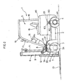
- a fork lift 1 as an example of a working vehicle is provided with a pair of left-and right front wheels (drive wheels) 3 to a front portion of a vehicle body 2, a pair of left and right rear wheels (idler. wheels) 4 to a rear portion thereof, and a driver's seat 5 above the front portion of the vehicle body 2.
- a vertically extendable mast 6 is disposed at the front end section of the aforementioned vehicle body 2 to be rotatable in a longitudinal direction via a connecting shaft 7 in a vehicle width direction, a tilt cylinder 8 which effects the longitudinal rotation is provided between the vehicle body 2 and the mast 6.
- the mast 6 is constructed by a pair of left and right outer frames 9 at a side of the fork lift 1, and a pair of left and right inner frames 10 descendable and ascendable by being guided by the outer frames 9, and a lift cylinder 11 is provided between the outer frame 9 and the inner frame 10.
- a lift bracket 12 is provided to be capable of vertically moving by being guided on the inner frame 10, and a pair of left and right forks 13 are attached to the lift bracket 12 via a pair of vertical finger bars.
- the driver's seat 5 is provided with a seat 15, a steering wheel 16 located in front of the seat 15 and the like, and a head guard 19 is provided thereabove via a front pipe 17 and a rear pipe 18 which are erected from the vehicle body 2. Further, a counterweight 20 is provided at a back of the seat 15 on the vehicle body 2.
- the pair of left and right front wheels 3 and the pair of the left and right rear wheels 4 are mounted to the vehicle body 2 so that they can be turned by 90 degrees (laterally turnable at substantially right angles).
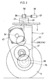
- vertical shafts 26 are provided to be rotatable around vertical axes 27 via the respective bearings 25.
- a transmission device case body 31 of a transmission device 30 is fixed at a lower end of the vertical axis 26, whereby the transmission device 30 is mounted to the vehicle body 2 to be rotatable around the vertical axis 27.
- the transmission device case body 31 is constructed by an inner case part 31A in an inverted L-shape, and an outer case part 31B attached to an outer face side of a vertical plate portion in this inner case part 31A, and a lateral plate portion of the inner case part 31A is fixed at a lower end of the vertical axis 26.
- an oil seal 32 can be placed in a penetrated portion formed in the inner case part 31A, and a bearing 33 can be placed in a recessed portion formed in the outer case part 31B.
- a cylindrical driving gear (driving portion) 34 is rotatably supported by this bearing 33 via a cylindrical boss portion 34a.
- an axle 28 is rotatably provided via a wheel bearing 35 at the inner case part 31A in the lower part of the transmission device case body 31, a driven gear (driven part) 36 is attached to the axle 28 to be located inside the transmission device case body 31, a rim 3A of the front wheel 3 is detachably attached to a part projected to the outside of the transmission device case body 31 via a rotational flange 29 and the like.
- the driving gear 34 and the driven gear 36 are operatively connected via a reduction gear mechanism 37 located inside the transmission device case body 31.
- An example of the transmission device 30 is constructed by the above-described components 31 to 37.
- a case body 41 of the electric motor 40 is constructed by a cylindrical outer case part 41A, and a non-loaded side bracket 41B which blocks a non-loaded side end portion (non-loaded side end) of the outer case part 41A, and a loaded side end portion of the outer case part 41A is integrated with a inner face side of the vertical plate portion of the inner case part 31A in the transmission device case body 31 by welding or the like.
- the inner case part 31A of the transmission device case body 31 is also used as a loaded side end bracket in the electric motor 40.
- a stator component such as a stator 42 is provided on an inner circumferential face of the outer case part 41A.
- the drive shaft 44 mounted with a rotor 43 is placed inside the case body 41, and one end of the drive shaft 44 is rotatably supported at a bearing 45 in a recessed portion formed in the non-loaded side bracket 41B. The other end of the drive shaft 44 is inserted through the driving gear 34 and connected therewith
- the other end of the drive shaft 44 is rotatably supported at the outer case part 31B of the transmission device case body 31 via the cylindrical boss part 34a of the driving gear 34 and the bearing 33.
- the driving gear 34 provided at the other end of the drive shaft 44 is operatively connected to the axle 28 via the reduction gear mechanism 37 and the driven gear 36, whereby the pair of left and right front wheels 3 are operatively connected to the respective drive shafts 44 of the electric motors 40.
- the front wheel 3 is constructed to be located at an area immediately below the vertical axis 27.
- An example of the electric motor 40 is constructed by the above-described components 41 to 45 and the like.
- a battery 50 is mounted on the vehicle body 2, and a controller 51 is attached to the battery 50.
- a cable 52 from the controller 51 is connected to each of the electric motors 40.
- Front wheel rotating means 55 for rotating the left and right transmission devices 30 are provided.
- a turning cylinder 57 is provided to be relatively rotatable between a link 56 provided at an upper end portion of the vertical shafts 26 and the vehicle body 2, whereby the left and right front wheels 3 are constructed to turn in opposite directions from each other to face laterally at substantially right angles, by extension movement of the turning cylinder 57.
- An example of the front wheel rotating means 55 is constructed by the above-described components 56, 57 and the like.
- a rim 4A is attached to a vertical plate portion in a turning member 60 via an axle and the like to be freely rotatable, and a lateral plate portion in the turning member 60 is attached to the vehicle body 2 to be rotatable around a vertical axis 63 via a wheel bearing 61 and a vertical shaft 62.
- the rear wheel 4 is constructed to be located at an area immediately below the vertical axis 63.
- Rear wheel rotating means 65 for rotating the left and right turning members 60 is provided. Namely, free ends of links 66 provided at upper end portions of the vertical shafts 62 are connected by a common link 67 in a vehicle width direction, and a turning cylinder 68 is provided between a middle portion of the common link 67 and the vehicle body 2 to be relatively rotatable. Accordingly, the left and right front wheels 3 are constructed to be turned in the same direction to face laterally at substantially right angles by extension movement of the turning cylinder 68.
- An example of the rear wheel rotating means 65 is constructed by the above-described components 66 to 68 and the like.
- the electric motor 40 section a loaded side end portion of the outer case part 41A in the case body 41 is directly connected to the inner case part 31A of the transmission device case body 31, and the other end of the drive shaft 44 is rotatably supported by the outer case part 31B of the transmission device case body 31, whereby the electric motor 40 section can be constructed to be compact with excellent assembling easiness.
- the electric motor 40 is located under the vertical axis 27, whereby the width of the front wheel part which is turned, namely, the space for turning can be made smaller, and the width of the vehicle body 2 (length) is decreased, thus making it possible to reduce the entire body in size.
- FIG. 1 and FIG. 2, and FIG. 4 show situations at the time of normal traveling.
- the left and right front wheels 3 and the left and right rear wheels 4 face the longitudinal direction.
- the fork lift 1 like this can travel by operation of the steering wheel 16 by the operator seated in the seat 15 of the driver's seat 5.
- electric power of the battery 50 is controlled by the controller 51, and thereafter it is supplied to the electric motors 40 via the cable 52, whereby the front wheels 3 are driven in a normal and reverse direction and the fork lift 1 can travel in a longitudinal direction.
- the lift cylinder 11 is operated by manipulating the lift lever, whereby the fork 13 can be hoisted and lowered along the mast 6 via the lift bracket 12 and the like, thus making it possible to perform a fork operation for a predetermined period of time.
- the tilt cylinder 8 is operated by manipulating the tilt lever, whereby the mast 6 can be rotated (tilted) around the connecting shaft 7, thus making it possible to change the posture of the fork 13 via the lift bracket 12 and the like.
- the front wheel rotating means 55 and the rear wheel rotating means 65 are operated by manipulating a lever type lateral mode switch (not shown) at first to tilt the lever.
- both the turning cylinders 57 of the front wheel rotating means 55 are synchronized and extended, and the transmission devices 30 are rotated in a reverse direction around the vertical axes 27 via the links 56, whereby the front wheels 3 are turned by 90 degrees with respect to the vehicle body 2 (laterally turned at substantially right angles) as shown by the phantom lines in FIG. 1 and FIG. 2, and FIG. 5.
- the electric motors 40 and the front wheels 3 are located under the vertical axes 27 in this situation, the electric motors 40, the front wheels 3 and the like can be turned to 90 degrees easily, smoothly, and compactly.
- the turning cylinder 68 of the rear wheel rotating means 65 is extensively moved, and the turning members 60 are rotated in the same direction around the vertical axes 63 via the common link 67 and the links 66, whereby the rear wheels 4 are turned by 90 degrees (laterally turned at substantially right angles) with respect to the vehicle body 2 as shown by the phantom lines in FIG. 1 and FIG. 2, and FIG. 5. Since the rear wheels 4 are located under the vertical axes 63, the rear wheels 4 and the like are made compact and can be turned by 90 degrees.
- lateral traveling can be performed as described above, for example, an elongate object can be transported easily via the fork 13. Compensation of straightness in lateral traveling is facilitated by tilting the lever longitudinally to operate the turning cylinder 57 slightly to perform fine tuning of the angles of the front wheels 3, or by operating the turning cylinder 68 slightly to perform fine tuning of the angles of the rear wheels 4.
- a counter type fork lift 1 is shown as a working vehicle, but the same operation can be obtained if a large-scale transporter, a loader, a side fork lift and the like are used as the working vehicle.
- the cylindrical driving gear 34 is adopted as the drive part to make a type in which the drive shaft 44 is linked with the driving gear 34, but this may be a drive part of a type in which a driving gear is directly formed at the other end of the drive shaft 44.
- the number of the components of the transmission device 30 can be reduced and the construction can be further simplified.
- one of the rear wheels 4 may be a steering type by a handle wheel, and the other one of the rear wheels 4 may be a turning caster type, and in this case, when switching to lateral traveling, the one of the rear wheels 4 is forcibly turned by the cylinder and the like.
Applications Claiming Priority (3)
| Application Number | Priority Date | Filing Date | Title |
|---|---|---|---|
| JP2000391736 | 2000-12-25 | ||
| JP2000391736A JP3995412B2 (ja) | 2000-12-25 | 2000-12-25 | 横行システムを持った作業車両 |
| PCT/JP2001/005603 WO2002051738A1 (fr) | 2000-12-25 | 2001-06-28 | Vehicule de chantier avec systeme de deplacement transversal |
Publications (3)
| Publication Number | Publication Date |
|---|---|
| EP1350754A1 true EP1350754A1 (de) | 2003-10-08 |
| EP1350754A4 EP1350754A4 (de) | 2004-07-07 |
| EP1350754B1 EP1350754B1 (de) | 2005-03-02 |
Family
ID=18857834
Family Applications (1)
| Application Number | Title | Priority Date | Filing Date |
|---|---|---|---|
| EP01945687A Expired - Lifetime EP1350754B1 (de) | 2000-12-25 | 2001-06-28 | Arbeitsfahrzeug mit querfahrtmöglichkeit |
Country Status (9)
| Country | Link |
|---|---|
| US (1) | US6688416B2 (de) |
| EP (1) | EP1350754B1 (de) |
| JP (1) | JP3995412B2 (de) |
| KR (1) | KR100735602B1 (de) |
| CN (1) | CN1241823C (de) |
| AT (1) | ATE289978T1 (de) |
| DE (1) | DE60109206D1 (de) |
| TW (1) | TW499390B (de) |
| WO (1) | WO2002051738A1 (de) |
Families Citing this family (25)
| Publication number | Priority date | Publication date | Assignee | Title |
|---|---|---|---|---|
| JP3874595B2 (ja) * | 2000-08-01 | 2007-01-31 | Tcm株式会社 | 横行システムを持ったフォークリフト |
| DE10334449A1 (de) * | 2003-07-29 | 2005-03-03 | Zf Friedrichshafen Ag | Antriebseinheit für Flurförderfahrzeuge |
| DE10343857A1 (de) * | 2003-09-23 | 2005-04-28 | Linde Ag | Antriebsaggregat für ein Flurförderzeug, insbesondere Deichsel-Hubwagen |
| DE102004006722A1 (de) * | 2004-02-11 | 2005-09-01 | Zf Friedrichshafen Ag | Lenk- und Radantrieb für ein Flurförderzeug |
| DE102005047958A1 (de) * | 2005-10-06 | 2007-06-14 | Jungheinrich Ag | Antriebs- und Lenkvorrichtung für ein Flurförderzeug |
| DE102005058400A1 (de) * | 2005-11-30 | 2007-05-31 | Jungheinrich Ag | Antriebs- und Lenkeinheit für ein Rad eines Flurförderzeugs |
| DE102005058942A1 (de) * | 2005-12-09 | 2007-07-12 | Zf Friedrichshafen Ag | Antrieb für Flurförderfahrzeuge |
| DE102006027369A1 (de) * | 2006-06-13 | 2007-12-27 | Jungheinrich Aktiengesellschaft | Lenkantrieb für ein gelenktes Rad eines Flurförderzeugs, insbesondere eines Hinterrades eines Dreirad-Flurförderzeugs |
| DE102006038396A1 (de) * | 2006-08-15 | 2008-02-21 | Kordel Antriebstechnik Gmbh | Frontachsgetriebe |
| EP1946952A1 (de) * | 2007-01-16 | 2008-07-23 | ABM Greiffenberger Antriebstechnik GmbH | Antriebseinheit für ein Flurförderfahrzeug |
| US20080277890A1 (en) * | 2007-05-07 | 2008-11-13 | Boster Ii Roger D | Four-Way Forklift With Outwardly Pivoting Wheel Arms |
| CN101348126B (zh) * | 2007-07-16 | 2011-05-04 | 浙江佳力科技股份有限公司 | 叉车转向装置 |
| JP4980825B2 (ja) * | 2007-08-28 | 2012-07-18 | 日立オートモティブシステムズ株式会社 | ステアリング装置 |
| KR100970422B1 (ko) | 2008-07-31 | 2010-07-15 | 그린모텍(주) | 전동지게차용 주행 조향장치 |
| US20140308097A1 (en) * | 2011-06-30 | 2014-10-16 | Murata Machinery, Ltd. | Forklift, automatic warehouse using same, and cargo handling method using forklift |
| CN106114196A (zh) * | 2011-07-08 | 2016-11-16 | 日本电产株式会社 | 车轮单元 |
| JP2013112103A (ja) * | 2011-11-28 | 2013-06-10 | Ntn Corp | 自動車 |
| CN104326406B (zh) * | 2014-10-29 | 2016-08-24 | 滨州学院 | 一种全向移动式多功能叉车 |
| CN206049786U (zh) * | 2016-01-05 | 2017-03-29 | 陈生泰 | 动力自带轮及圆盘式360度动力转弯系统 |
| JP6786354B2 (ja) * | 2016-10-31 | 2020-11-18 | Ntn株式会社 | インホイールモータ駆動装置 |
| CN107953929A (zh) * | 2017-08-01 | 2018-04-24 | 郝巍 | 一种自由转弯的翻堆机 |
| CN110654229B (zh) * | 2018-06-29 | 2021-09-03 | 比亚迪股份有限公司 | 轮边驱动系统以及车辆 |
| CN109721007A (zh) * | 2019-01-30 | 2019-05-07 | 集美大学诚毅学院 | 一种叉车支撑装置 |
| JP7348093B2 (ja) * | 2020-01-27 | 2023-09-20 | ダイムラー トラック エージー | 電動トラック用の駆動装置 |
| WO2021192813A1 (ja) * | 2020-03-25 | 2021-09-30 | Ntn株式会社 | インホイールモータ駆動装置 |
Citations (3)
| Publication number | Priority date | Publication date | Assignee | Title |
|---|---|---|---|---|
| JPS5284649A (en) * | 1975-12-29 | 1977-07-14 | Suzuki Motor Co Ltd | Car steering apparatus |
| DE29519489U1 (de) * | 1995-01-24 | 1996-01-25 | Steyr Daimler Puch Ag | Radantriebseinheit für Elektrofahrzeuge |
| US5691584A (en) * | 1993-09-09 | 1997-11-25 | Honda Giken Kogyo Kabushiki Kaisha | Wheel motor for vehicles |
Family Cites Families (8)
| Publication number | Priority date | Publication date | Assignee | Title |
|---|---|---|---|---|
| US4823899A (en) * | 1986-07-10 | 1989-04-25 | Ashot Ashkelon Industries Ltd. | Steering apparatus |
| JPH0764272B2 (ja) * | 1989-05-22 | 1995-07-12 | 有限会社カーネル | 自走式作業台車 |
| US5128598A (en) * | 1990-12-13 | 1992-07-07 | Raymond Corporation | Material handling vehicle steering system |
| JPH05246346A (ja) | 1992-03-09 | 1993-09-24 | Mitsubishi Heavy Ind Ltd | 運搬台車 |
| US5609220A (en) * | 1992-08-27 | 1997-03-11 | Kabushiki Kaisha Komatsu Seisakusho | Operation control system for traveling vehicle |
| JPH10244951A (ja) | 1997-03-07 | 1998-09-14 | Meidensha Corp | フォークリフト |
| AU8662498A (en) * | 1997-07-25 | 1999-02-16 | Albert Madwed | Independently pivotable drivewheel for a wheeled chassis |
| DE19904552A1 (de) * | 1998-03-19 | 1999-09-23 | Linde Ag | Radantrieb für Flurförderzeuge |
-
2000
- 2000-12-25 JP JP2000391736A patent/JP3995412B2/ja not_active Expired - Fee Related
-
2001
- 2001-06-20 TW TW090115009A patent/TW499390B/zh not_active IP Right Cessation
- 2001-06-28 AT AT01945687T patent/ATE289978T1/de not_active IP Right Cessation
- 2001-06-28 DE DE60109206T patent/DE60109206D1/de not_active Expired - Lifetime
- 2001-06-28 CN CNB018055788A patent/CN1241823C/zh not_active Expired - Fee Related
- 2001-06-28 WO PCT/JP2001/005603 patent/WO2002051738A1/ja active IP Right Grant
- 2001-06-28 EP EP01945687A patent/EP1350754B1/de not_active Expired - Lifetime
- 2001-06-28 US US10/204,791 patent/US6688416B2/en not_active Expired - Fee Related
- 2001-06-28 KR KR1020027011061A patent/KR100735602B1/ko not_active IP Right Cessation
Patent Citations (3)
| Publication number | Priority date | Publication date | Assignee | Title |
|---|---|---|---|---|
| JPS5284649A (en) * | 1975-12-29 | 1977-07-14 | Suzuki Motor Co Ltd | Car steering apparatus |
| US5691584A (en) * | 1993-09-09 | 1997-11-25 | Honda Giken Kogyo Kabushiki Kaisha | Wheel motor for vehicles |
| DE29519489U1 (de) * | 1995-01-24 | 1996-01-25 | Steyr Daimler Puch Ag | Radantriebseinheit für Elektrofahrzeuge |
Non-Patent Citations (2)
| Title |
|---|
| PATENT ABSTRACTS OF JAPAN vol. 0011, no. 41 (M-047), 17 November 1977 (1977-11-17) & JP 52 084649 A (SUZUKI MOTOR CO LTD), 14 July 1977 (1977-07-14) * |
| See also references of WO02051738A1 * |
Also Published As
| Publication number | Publication date |
|---|---|
| WO2002051738A1 (fr) | 2002-07-04 |
| ATE289978T1 (de) | 2005-03-15 |
| DE60109206D1 (de) | 2005-04-07 |
| US20030029660A1 (en) | 2003-02-13 |
| KR100735602B1 (ko) | 2007-07-06 |
| EP1350754B1 (de) | 2005-03-02 |
| CN1406204A (zh) | 2003-03-26 |
| TW499390B (en) | 2002-08-21 |
| JP3995412B2 (ja) | 2007-10-24 |
| JP2002193133A (ja) | 2002-07-10 |
| US6688416B2 (en) | 2004-02-10 |
| CN1241823C (zh) | 2006-02-15 |
| EP1350754A4 (de) | 2004-07-07 |
| KR20020091099A (ko) | 2002-12-05 |
Similar Documents
| Publication | Publication Date | Title |
|---|---|---|
| EP1350754B1 (de) | Arbeitsfahrzeug mit querfahrtmöglichkeit | |
| US6913102B2 (en) | Working vehicle with traversing system | |
| JP3874595B2 (ja) | 横行システムを持ったフォークリフト | |
| JP3919429B2 (ja) | 横行システムを持った作業車両 | |
| US6732824B2 (en) | Working vehicle with transverse travel system | |
| KR100700390B1 (ko) | 가로주행 시스템을 갖는 포크리프트 | |
| JP2003191860A (ja) | 車両の四輪操舵装置及び車両 | |
| JP3919427B2 (ja) | 横行システムを持った作業車両 | |
| JP3121806B1 (ja) | 横行システムを持ったフォークリフト | |
| JP3140005B2 (ja) | 横行システムを持ったフォークリフト | |
| JP2002029446A (ja) | 横行システムを持った作業車両 | |
| JP3121809B1 (ja) | 横行システムを持ったフォークリフト | |
| JP3272339B2 (ja) | 横行システムを持ったフォークリフト | |
| JP2002087316A (ja) | 横行システムを持った作業車両 | |
| JP2002274791A (ja) | 横行システムを持った作業車両 | |
| JPH08324447A (ja) | 車両の車輪換向装置 |
Legal Events
| Date | Code | Title | Description |
|---|---|---|---|
| PUAI | Public reference made under article 153(3) epc to a published international application that has entered the european phase |
Free format text: ORIGINAL CODE: 0009012 |
|
| 17P | Request for examination filed |
Effective date: 20030725 |
|
| AK | Designated contracting states |
Kind code of ref document: A1 Designated state(s): AT BE CH CY DE DK ES FI FR GB GR IE IT LI LU MC NL PT SE TR |
|
| A4 | Supplementary search report drawn up and despatched |
Effective date: 20040526 |
|
| GRAP | Despatch of communication of intention to grant a patent |
Free format text: ORIGINAL CODE: EPIDOSNIGR1 |
|
| GRAS | Grant fee paid |
Free format text: ORIGINAL CODE: EPIDOSNIGR3 |
|
| GRAA | (expected) grant |
Free format text: ORIGINAL CODE: 0009210 |
|
| AK | Designated contracting states |
Kind code of ref document: B1 Designated state(s): AT BE CH CY DE DK ES FI FR GB GR IE IT LI LU MC NL PT SE TR |
|
| PG25 | Lapsed in a contracting state [announced via postgrant information from national office to epo] |
Ref country code: IT Free format text: LAPSE BECAUSE OF FAILURE TO SUBMIT A TRANSLATION OF THE DESCRIPTION OR TO PAY THE FEE WITHIN THE PRESCRIBED TIME-LIMIT;WARNING: LAPSES OF ITALIAN PATENTS WITH EFFECTIVE DATE BEFORE 2007 MAY HAVE OCCURRED AT ANY TIME BEFORE 2007. THE CORRECT EFFECTIVE DATE MAY BE DIFFERENT FROM THE ONE RECORDED. Effective date: 20050302 Ref country code: FI Free format text: LAPSE BECAUSE OF FAILURE TO SUBMIT A TRANSLATION OF THE DESCRIPTION OR TO PAY THE FEE WITHIN THE PRESCRIBED TIME-LIMIT Effective date: 20050302 Ref country code: FR Free format text: LAPSE BECAUSE OF NON-PAYMENT OF DUE FEES Effective date: 20050302 Ref country code: CH Free format text: LAPSE BECAUSE OF FAILURE TO SUBMIT A TRANSLATION OF THE DESCRIPTION OR TO PAY THE FEE WITHIN THE PRESCRIBED TIME-LIMIT Effective date: 20050302 Ref country code: AT Free format text: LAPSE BECAUSE OF FAILURE TO SUBMIT A TRANSLATION OF THE DESCRIPTION OR TO PAY THE FEE WITHIN THE PRESCRIBED TIME-LIMIT Effective date: 20050302 Ref country code: BE Free format text: LAPSE BECAUSE OF FAILURE TO SUBMIT A TRANSLATION OF THE DESCRIPTION OR TO PAY THE FEE WITHIN THE PRESCRIBED TIME-LIMIT Effective date: 20050302 Ref country code: LI Free format text: LAPSE BECAUSE OF FAILURE TO SUBMIT A TRANSLATION OF THE DESCRIPTION OR TO PAY THE FEE WITHIN THE PRESCRIBED TIME-LIMIT Effective date: 20050302 Ref country code: NL Free format text: LAPSE BECAUSE OF FAILURE TO SUBMIT A TRANSLATION OF THE DESCRIPTION OR TO PAY THE FEE WITHIN THE PRESCRIBED TIME-LIMIT Effective date: 20050302 Ref country code: TR Free format text: LAPSE BECAUSE OF FAILURE TO SUBMIT A TRANSLATION OF THE DESCRIPTION OR TO PAY THE FEE WITHIN THE PRESCRIBED TIME-LIMIT Effective date: 20050302 |
|
| REG | Reference to a national code |
Ref country code: GB Ref legal event code: FG4D |
|
| REG | Reference to a national code |
Ref country code: CH Ref legal event code: EP |
|
| REG | Reference to a national code |
Ref country code: IE Ref legal event code: FG4D |
|
| REF | Corresponds to: |
Ref document number: 60109206 Country of ref document: DE Date of ref document: 20050407 Kind code of ref document: P |
|
| PG25 | Lapsed in a contracting state [announced via postgrant information from national office to epo] |
Ref country code: GR Free format text: LAPSE BECAUSE OF FAILURE TO SUBMIT A TRANSLATION OF THE DESCRIPTION OR TO PAY THE FEE WITHIN THE PRESCRIBED TIME-LIMIT Effective date: 20050602 Ref country code: DK Free format text: LAPSE BECAUSE OF FAILURE TO SUBMIT A TRANSLATION OF THE DESCRIPTION OR TO PAY THE FEE WITHIN THE PRESCRIBED TIME-LIMIT Effective date: 20050602 |
|
| PG25 | Lapsed in a contracting state [announced via postgrant information from national office to epo] |
Ref country code: DE Free format text: LAPSE BECAUSE OF FAILURE TO SUBMIT A TRANSLATION OF THE DESCRIPTION OR TO PAY THE FEE WITHIN THE PRESCRIBED TIME-LIMIT Effective date: 20050603 |
|
| PG25 | Lapsed in a contracting state [announced via postgrant information from national office to epo] |
Ref country code: ES Free format text: LAPSE BECAUSE OF FAILURE TO SUBMIT A TRANSLATION OF THE DESCRIPTION OR TO PAY THE FEE WITHIN THE PRESCRIBED TIME-LIMIT Effective date: 20050613 |
|
| PG25 | Lapsed in a contracting state [announced via postgrant information from national office to epo] |
Ref country code: IE Free format text: LAPSE BECAUSE OF NON-PAYMENT OF DUE FEES Effective date: 20050628 Ref country code: LU Free format text: LAPSE BECAUSE OF NON-PAYMENT OF DUE FEES Effective date: 20050628 Ref country code: GB Free format text: LAPSE BECAUSE OF NON-PAYMENT OF DUE FEES Effective date: 20050628 Ref country code: CY Free format text: LAPSE BECAUSE OF FAILURE TO SUBMIT A TRANSLATION OF THE DESCRIPTION OR TO PAY THE FEE WITHIN THE PRESCRIBED TIME-LIMIT Effective date: 20050628 |
|
| PG25 | Lapsed in a contracting state [announced via postgrant information from national office to epo] |
Ref country code: MC Free format text: LAPSE BECAUSE OF NON-PAYMENT OF DUE FEES Effective date: 20050630 |
|
| NLV1 | Nl: lapsed or annulled due to failure to fulfill the requirements of art. 29p and 29m of the patents act | ||
| PG25 | Lapsed in a contracting state [announced via postgrant information from national office to epo] |
Ref country code: PT Free format text: LAPSE BECAUSE OF FAILURE TO SUBMIT A TRANSLATION OF THE DESCRIPTION OR TO PAY THE FEE WITHIN THE PRESCRIBED TIME-LIMIT Effective date: 20050907 |
|
| REG | Reference to a national code |
Ref country code: CH Ref legal event code: PL |
|
| PLBE | No opposition filed within time limit |
Free format text: ORIGINAL CODE: 0009261 |
|
| STAA | Information on the status of an ep patent application or granted ep patent |
Free format text: STATUS: NO OPPOSITION FILED WITHIN TIME LIMIT |
|
| 26N | No opposition filed |
Effective date: 20051205 |
|
| GBPC | Gb: european patent ceased through non-payment of renewal fee |
Effective date: 20050628 |
|
| REG | Reference to a national code |
Ref country code: IE Ref legal event code: MM4A |
|
| EN | Fr: translation not filed | ||
| PG25 | Lapsed in a contracting state [announced via postgrant information from national office to epo] |
Ref country code: SE Free format text: LAPSE BECAUSE OF FAILURE TO SUBMIT A TRANSLATION OF THE DESCRIPTION OR TO PAY THE FEE WITHIN THE PRESCRIBED TIME-LIMIT Effective date: 20050602 |