EP1350635A2 - Vorrichtung und Verfahren zum Bewegen von Büchern - Google Patents
Vorrichtung und Verfahren zum Bewegen von Büchern Download PDFInfo
- Publication number
- EP1350635A2 EP1350635A2 EP03007370A EP03007370A EP1350635A2 EP 1350635 A2 EP1350635 A2 EP 1350635A2 EP 03007370 A EP03007370 A EP 03007370A EP 03007370 A EP03007370 A EP 03007370A EP 1350635 A2 EP1350635 A2 EP 1350635A2
- Authority
- EP
- European Patent Office
- Prior art keywords
- container
- book
- books
- moving
- plane
- Prior art date
- Legal status (The legal status is an assumption and is not a legal conclusion. Google has not performed a legal analysis and makes no representation as to the accuracy of the status listed.)
- Withdrawn
Links
Images


Classifications
-
- B—PERFORMING OPERATIONS; TRANSPORTING
- B42—BOOKBINDING; ALBUMS; FILES; SPECIAL PRINTED MATTER
- B42C—BOOKBINDING
- B42C19/00—Multi-step processes for making books
- B42C19/08—Conveying between operating stations in machines
Definitions
- the present invention relates to the field of bookbinding machines and Book bundle devices, in particular an apparatus and a method for Moving books in or following a perfect binder.
- Automatic devices for binding sheets are known from the prior art known that one or more e.g. have pneumatically actuated transport tongs, into which the sheets to be bound are inserted and which the leaf bundles through all Promote binding stations.
- Typical generic devices have a vibrating level, which the leaves arranged flush to each other, a milling device is also provided, all of which Back of the blade leveled and possibly roughened, and rollers, discs or nozzles for Applying an adhesive to the back of the sheet and a feed device for the Cover that positions each cover on a cover station, as well as with one Pressing device for the cover with which it is attached to the whole of the sheets becomes. Afterwards, the perfect bound books are on the three open pages trimmed with a flush cutter.
- a device with which the flush cutting process is improved would be desirable can be, especially in the drying of the adhesive has advanced and therefore an improved flush cut can be achieved. Accordingly, it is Object of the present invention to provide a device by means of one Improvement of the flush cutting process in a device for binding books can be achieved due to more advanced adhesive drying.
- the device is a device for moving Books, wherein a number of movable containers is provided, which on one Transport device are arranged and with a fixed container next to the conveyor line is provided for the movable container, and with a Unloading device that fixes the books from the movable container to the arranged container passes.
- the device according to the invention is particularly advantageous only between the existing transport path of a generic Perfect binding device inserted.
- it is the movable containers around compartments that have a support surface inclined to the horizontal have the books and are provided with a stop against which the books strike due to the inclined contact surface.
- the transport device is advantageously at least one endless, paternoster-like device on which the movable containers are attached.
- Transport device is arranged such that the transport of the books vertically he follows.
- the required tree space that the device according to the invention needed kept particularly low.
- Adhesive binding devices are set up a relatively large amount of unused space.
- the books are at least partially cooled.
- Acting it is, for example, at least one electrically driven fan, advantageously by several electrically driven fans. Partly cool it down
- the books refer to the fact that the temperature of the books partially is lowered, on the other hand, the parts of the books, especially the spine, on the the glue was applied. This is particularly advantageous with so-called hot glues "Hot melts" that are widely used in the industry.
- the Controlled transport device such that the movable container along the Conveyor line to be moved gradually. This gradual movement is coming advantageously counter to the loading or unloading movement of the transport device.
- provided cooling devices on the transport device this affects gradually move the movable container out to the cooling process.
- the cooling device will be dimensioned such that the residence time during the Steps that brings the books into operative relationship with the cooler just enough to cool the books, especially the spines, to the desired temperature.
- the Unloading device arranged above the fixed container and consists of a movable arm, which has a driver for a book at its end, the arm is driven such that these drivers from the fixed container to outer edge of the movable container are movable.
- the drivers are vertically arranged rods that are directed downwards, said movable arm removing the bars from the fixed arranged container up to the outer edge of the movable container that promotes next the fixed container is arranged.
- the fixed container has a vertically arranged stop edge, which by a vertical position is pivotable in a position in which the edge with the support plane of the fixed container matches.
- the fixed one Container advantageously similar in geometry to the movable containers, so that the books can be easily pushed over from the movable containers onto the fixed container by means of the unloading device is possible.
- a further transport path can be released become. Due to an inclined support surface of the fixed container can the acceleration of gravity is used as a drive for the further transport of the books become.
- the device additionally comprises a slide which is flush with the support plane of the fixed container is arranged.
- the Acceleration of gravity can be exploited to move a book in vertically upwards to transport the original machining height.
- the device additionally has a fixed plane which is parallel in the surface Has longitudinal slots which are aligned along the conveying direction of a book and vertically arranged fingers are movably arranged in these slots and these vertically arranged fingers are driven by a device such that the Fingers come out of the plane and move along the corresponding slots to the opposite end of the plane that is near a subsequent one Flush cutting device is provided, and move your fingers under the plane be lowered and moved back to the original position.
- a Conveyor belt is mounted on two side guides that run parallel to the belt and this over the fixed level on the side of the beginning of the movement vertically arranged fingers are provided and the location of said conveyor belt can be adjusted in such a way by the guides mentioned that a tuning on the dimensions of the books and on the working speed of the subsequent ones Flush cutting device is carried out.
- the Transport speed of each book to the dimensions of the book itself the working speed of a subsequent processing device as well matched the feeding stroke of a book to the device for moving books.
- the data required to determine the working speed will be advantageously determined by sensors and / or by an operator interface entered and / or taken over by a higher-level control.
- the device according to the invention also referred to below as a cooling tower, exists of two side columns (C), a number of movable containers (V) and one fixed container (F) on top and two conveyor chains (O) for conveying the movable container (V) in the vertical direction.
- the two pillars (C) are parallel arranged to each other and have on their inside chains (O) for taking the movable container (V).
- one or two electrically driven fans (E) are provided and one Dispenser (S).
- the moveable containers are generally L-shaped, i.e. they have a support level (Vp), which emerges from a pressing device of an adhesive binding device Record and carry the book. Furthermore, the containers have a stop edge (Vb) the back of the book, which lies on the level (Vp) of the container (V) comes to lie. As can be seen in FIGS. 1 and 2, the support plane (Vp) is arranged inclined to the horizontal, so that one on the support plane (Vp) strikes the book due to the bevel on the stop edge (Vb).
- the movable containers (V) are connected with straps, bands or chains (O), in the way that the stop edge (Vb) is aligned with the columns (C) and in such a way that the plane (Vp) of the containers is inclined, with an inclination in the direction of the stop edge (Vb).
- the containers (V) are moved upwards via the chains (O). The movement takes place gradually and until the fixed container (F) has been reached. in the The containers then move in an overturned position to the bottom of the columns (C) along the ring-shaped chain run (O).
- the fixed container (F) has a shape and dimensions similar to that of is movable container (V), the fixed container laterally on one of the two pillars (C) at the highest point, that of the movable Containers (V) is accessible.
- the fixed container is essentially located (F) laterally aligned to the uppermost movable container (V) before this movable container Container (V), which is driven by the chains (O), its return movement to Bottom of the cooling tower begins.
- Said fixed container (F) has in particular on a fixed support level (Fp) and has a stop edge (Fb), which is rotatably provided and, if necessary, aligned with the support plane (Fp) can be achieved. This will make the transport path to the slide (R) Approved.
- An unloading device (S) is provided above the fixed container (F) is advantageously formed by an arm (Sb) movable in the horizontal plane, the driver (Sa) at its end, in the embodiment shown two or has a plurality of vertically arranged rods (Sa) which are directed downwards.
- the movable arm (Sb) is parallel to the stop edge (Fb) of the fixed arranged container (F) aligned, whereas the vertically arranged rods (Sa) have different lengths to close to the support level (Fp) of the fixed arranged container (F) to arrive.
- the slidable arm (Sb) is mounted in such a way that the displaceable arm (Sb) a lateral displacement of the vertically arranged Bars (Sa) to the edge (Vi) of the movable container (V) allows.
- the connecting slide (R) is in line with the stop edge (Fb) of the fixed arranged container arranged and ends above the adjustable conveyor belt (N) the step-by-step feed device.
- the feed device has a fixed plane (P), which is connected to movable, vertically arranged fingers (Pd) is equipped on which an adjustable Conveyor belt is arranged.
- the fixed plane (P) shows in its area Longitudinal slots (Pf), which are arranged parallel to each other and along the Feed direction of the book.
- slots (Pf) are movable, vertical arranged fingers (Pd) provided.
- These vertically arranged fingers (Pd) are from driven a device that lifts the fingers so that they out of the plane (P) and exit near the conveyor belt (N).
- the fingers (Pd) move along the corresponding slots (Pf) to the opposite end of the plane (P), which is located in the vicinity of an adjacent flush cutting device, wherein the fingers are lowered below said level (P) and returned to their starting position become.
- the conveyor belt (N) consists of a conveyor belt (N) on two lateral Guides (G) is arranged, which are aligned parallel to the belt (N). This enable the position of the said band (N) along its direction of advance niejust Schl.
- the book consisting of sheets and a cover, which has just been glued to the still is not cooled, connected, are passed to the cooling tower, in particular the books each reach a movable container (V) below, the Back rests against the stop edge (Vb) of the container (V).
- the chains (O) move the whole of the movable containers (V) and bring them in Order in front of the electric fans (E) that create an air flow towards the Blow the spine of the book and cool it down.
- each movable container (V) remains in its movement for a period of time necessary to receive a book take and allow the book to the air flow of the electrically powered Fans (E) is suspended for the necessary time and a desired, especially complete cooling of the glue on the back of the leaves and the Cover has been applied, causes.
- the adhesive has not cooled completely, but only to the extent that the adhesive is in completely cools down on the subsequent transport route to be completed. Thereby can speed up the transportation of books along the transportation route can be achieved, which increases the performance of the perfect binder.
- the corresponding movable container (V) then reaches the fixed container (F) and is aligned with this, the movable Arm (Sb) moves back and moves using its vertically arranged bars (Sa) the book from the movable container (V) to the fixed container (F). Then the movable container (V) moves, which is conveyed over the chains (O) in its return path and moves down to the base of the cooling tower to record a new book there.
- the fixed container (F) after receiving a book swivels its stop edge (Fb) into a position aligned with the support plane (Fp) and passes the corresponding book to the connecting slide (R) afterwards then raise the stop margin (Fb) again to receive another book to take.
- the book in descent on the connecting slide (R) reaches the conveyor belt (N) of a subsequent feed device, the gradual is driven and delivers the book to level (P).
- This conveyor belt (N) is arranged along the guides (G) such that the feed movement of each Book to the dimensions of the book itself, to the speed of work of the Flush cutting device and to the feeding cycle of a book to the cooling tower is voted.
- the book placed on the conveyor belt (N) of level (E) is about the vertically arranged fingers (Pd) moved to the flush cutting device.
Landscapes
- Auxiliary Devices For And Details Of Packaging Control (AREA)
- Chain Conveyers (AREA)
- Discharge Of Articles From Conveyors (AREA)
- Basic Packing Technique (AREA)
Abstract
Description
- Figur 1
- zeigt eine schematische Vorderansicht der erfindungsgemäßen Vorrichtung;
- Figur 2
- zeigt eine schematische Seitenansicht der erfindungsgemäßen Vorrichtung;
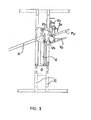
- Figur 3
- zeigt eine schematische Seitenansicht eines sich an die in den Fig. 1 und 2 gezeigte erfindungsgemäße Vorrichtung anschließenden Teils der erfindungsgemäßen Vorrichtung sowie Teile eines Bündigschneiders;
- Figur 4
- zeigt eine schematische Draufsicht des in Fig. 3 gezeigten Teils der erfindungsgemäßen Vorrichtung.
- C
- Säule
- E
- Kühlvorrichtung / Ventilator
- F
- fest angeordneter Behälter
- Fb
- Anschlagrand
- Fp
- Auflageebene
- G
- seitliche Führung
- N
- Transportband
- O
- Förderkette
- P
- fest angeordnete Ebene
- Pd
- Finger
- Pf
- Schlitz
- R
- Verbindungsrutsche
- S
- Entladevorrichtung
- Sa
- Stange
- Sb
- beweglicher Arm
- V
- beweglicher Behälter
- Vb
- Anschlagrand
- Vi
- seitlicher Rand
- Vp
- Auflageebene
Claims (13)
- Vorrichtung zum Bewegen von Büchern,
dadurch gekennzeichnet, dass eine Anzahl beweglicher Behälter (V) vorgesehen ist, die an einer Transportvorrichtung (C, O) angeordnet sind und mit einem fest angeordneten Behälter (F), der neben der Förderstrecke für die beweglichen Behälter (V) vorgesehen ist, sowie mit einer Entladevorrichtung (S), welche die Bücher von den beweglichen Behälter (V) an den fest angeordneten Behälter (F) übergibt. - Vorrichtung zum Bewegen von Büchern, nach Anspruch 1,
dadurch gekennzeichnet, dass die Transportvorrichtung (C, O) derartig angeordnet ist, dass ein vertikaler Transport der Bücher erfolgt. - Vorrichtung zum Bewegen von Büchern, nach einem der Ansprüche 1 bis 2,
dadurch gekennzeichnet, dass entlang der Förderstrecke für die beweglichen Behälter (V) wenigstens eine Kühleinrichtung (E) vorgesehen ist, vermittels die Bücher zumindest teilweise gekühlt werden. - Vorrichtung zum Bewegen von Büchern, nach einem der Ansprüche 1 bis 3,
dadurch gekennzeichnet, dass die Transportvorrichtung (C, O) derartig angesteuert wird, dass die beweglichen Behälter (V) entlang der Förderstrecke schrittweise bewegt werden. - Vorrichtung zum Bewegen von Büchern, nach einem der Ansprüche 1 bis 4,
dadurch gekennzeichnet, dass die Entladevorrichtung (S) über dem fest angeordneten Behälter (F) angeordnet ist und aus einem beweglichen Arm (Sb) besteht, der an seinem Ende Mitnehmer (Sa) für ein Buch aufweist, wobei der Arm derart angetrieben ist, dass diese Mitnehmer vom fest angeordneten Behälter (F) bis zum äußeren Rand (Vi) des beweglichen Behälters (V) bewegbar sind. - Vorrichtung zum Bewegen von Büchern, nach einem der Ansprüche 1 bis 5,
dadurch gekennzeichnet, dass der fest angeordnete Behälter einen vertikal angeordneten Anschlagsrand (Fp) aufweist, der von einer vertikalen Lage in eine Lage verschwenkbar ist, in der der Rand mit der Auflageebene (Fp) des fest angeordneten Behälters (F) übereinstimmt. - Vorrichtung zum Bewegen von Büchern, nach einem der Ansprüche 1 bis 6,
dadurch gekennzeichnet, dass die Vorrichtung zusätzlich eine Rutsche (R) umfasst, die fluchtend mit der Auflageebene (Fp) des fest angeordneten Behälters (F) angeordnet ist. - Vorrichtung zum Bewegen von Büchern, nach einem der Ansprüche 1 bis 7,
dadurch gekennzeichnet, dass die Vorrichtung zusätzlich eine fest angeordnete Ebene (P) aufweist, die in der Oberfläche parallele Längsschlitze (Pf) aufweist, die entlang der Förderrichtung eines Buches ausgerichtet sind und in diesen Schlitzen vertikal angeordnete Finger (Pd) beweglich angeordnet sind und diese vertikal angeordneten Finger (Pd) von einer Einrichtung derartig angetrieben werden, dass die Finger aus der Ebene (P) austreten und sich entlang der entsprechenden Schlitze (Pf) bis zum gegenüberliegenden Ende der Ebene (P), die in der Nähe einer nachfolgenden Bündigschneideinrichtung vorgesehen ist, bewegen und die Finger unter die Ebene (P) abgesenkt werden und in die Ursprungslage zurückbewegt werden. - Vorrichtung zum Bewegen von Büchern, Anspruch 8,
dadurch gekennzeichnet, dass ein Förderband (N) auf zwei seitlichen Führungen montiert ist, die parallel zum Band (N) verlaufen und diese über der fest angeordneten Ebene (P) auf der Seite des Bewegungsbeginnes der vertikal angeordneten Finger (Pd) vorgesehen sind und die Lage des genannten Transportbandes (N) durch die genannten Führungen (G) derartig einjustiert werden kann, dass ein Abstimmen auf die Abmessungen der Bücher und auf die Arbeitsgeschwindigkeit der nachfolgenden Bündigschneideinrichtung erfolgt. - Vorrichtung zum Bewegen von Büchern, einem der Ansprüche 1 bis 9,
dadurch gekennzeichnet, dass die Transportgeschwindigkeit eines jeden Buches an die Abmessungen des Buches selbst, an die Arbeitsgeschwindigkeit einer sich anschließenden Bearbeitungsvorrichtung sowie an den Zuführtakt eines Buches zur Vorrichtung zum Bewegen von Büchern abgestimmt wird. - Vorrichtung zum Bewegen von Büchern, einem der Ansprüche 1 bis 10,
dadurch gekennzeichnet, dass die Vorrichtung Teil einer Klebebindevorrichtung ist. - Verfahren zum Kühlen von Büchern mit den folgenden Schritten:a) Übergeben eines Buches von einer Klebebindestation an einen beweglich angeordneten Behälter (V);b) Schrittweises Bewegen des Buches mit dem beweglich angeordneten Behälter (V) bis zu einer Kühleinrichtung (E);c) Kühlen wenigstens teilweises Kühlen des Buches mit der Kühleinrichtung (E);d) Schrittweises Bewegen des Buches mit dem beweglich angeordneten Behälter (V) bis zu einer Entladevorrichtung (S), die über einem fest angeordneten Behälter (F) angeordnet ist;e) Entladen des Buches mit der Entladevorrichtung (S) auf den fest angeordneten Behälter (F).
- Verfahren nach Anspruch 12,
dadurch gekennzeichnet dass das Verfahren zusätzlich wenigstens einen der folgenden Verfahrensschritte umfasst:f) Freigeben eines sich anschließenden Transportpfades (R) durch Abschwenken eines Anschlages (Fb) des fest angeordneten Behälter (F) in eine mit der Ebene (Fp) des fest angeordneten Behälter (F) fluchtenden Ebene;g) diagonales Transportieren des Buches entlang einer Rutsche (R);h) seitliches Ausrichten des Buches auf einem sich anschließenden horizontalen Transportpfad (P) durch einjustierbare seitliche Führungen (G);i) horizontales Transportieren des Buches auf einem sich anschließenden horizontalen Transportpfad (P) durch vertikal angeordnete Finger (Pd) die in der Oberfläche des horizontalen Transportpfads (P) in parallelen Längsschlitzen (Pf) beweglich angeordnet sind und diese vertikal angeordneten Finger (Pd) von einer Einrichtung derartig angetrieben werden, dass die Finger aus der Ebene (P) austreten und sich entlang der entsprechenden Schlitze (Pf) bis zum gegenüberliegenden Ende der Ebene (P), die in der Nähe einer nachfolgenden Bündigschneideinrichtung vorgesehen ist, bewegen und die Finger unter die Ebene (P) abgesenkt werden und in die Ursprungslage zurückbewegt werden.
Applications Claiming Priority (2)
| Application Number | Priority Date | Filing Date | Title |
|---|---|---|---|
| IT2002PD000086A ITPD20020086A1 (it) | 2002-04-05 | 2002-04-05 | Dispositivo per il trasferimento di libri con raffreddamento del dorso |
| ITPD20020086 | 2002-04-05 |
Publications (2)
| Publication Number | Publication Date |
|---|---|
| EP1350635A2 true EP1350635A2 (de) | 2003-10-08 |
| EP1350635A3 EP1350635A3 (de) | 2007-05-23 |
Family
ID=27840315
Family Applications (1)
| Application Number | Title | Priority Date | Filing Date |
|---|---|---|---|
| EP03007370A Withdrawn EP1350635A3 (de) | 2002-04-05 | 2003-04-02 | Vorrichtung und Verfahren zum Bewegen von Büchern |
Country Status (4)
| Country | Link |
|---|---|
| US (1) | US20030188955A1 (de) |
| EP (1) | EP1350635A3 (de) |
| JP (1) | JP2003300614A (de) |
| IT (1) | ITPD20020086A1 (de) |
Cited By (1)
| Publication number | Priority date | Publication date | Assignee | Title |
|---|---|---|---|---|
| RU2324636C2 (ru) * | 2005-10-28 | 2008-05-20 | Илья Борисович Извозчиков | Устройство для укладывания предметных стекол в планшеты |
Families Citing this family (3)
| Publication number | Priority date | Publication date | Assignee | Title |
|---|---|---|---|---|
| CN108909258B (zh) * | 2018-08-10 | 2024-02-06 | 东莞市雅思机械设备有限公司 | 一种配页锁线联动机的双通道输送机构 |
| CN114750240B (zh) * | 2022-04-25 | 2023-09-22 | 广东金宣发包装科技有限公司 | 一种书本单页冲型的上料装置 |
| CN118565255B (zh) * | 2024-08-01 | 2024-12-03 | 江苏双辉环境科技有限公司 | 一种冷却塔自动清洗装置 |
Family Cites Families (22)
| Publication number | Priority date | Publication date | Assignee | Title |
|---|---|---|---|---|
| US1650971A (en) * | 1925-02-18 | 1927-11-29 | Goodrich Co B F | Conveyer |
| US1991237A (en) * | 1931-04-17 | 1935-02-12 | Snead & Company | Library conveyer system |
| US3235101A (en) * | 1962-10-16 | 1966-02-15 | Speaker Sortation Systems Inc | Semi-automatic transferring apparatus |
| US3405498A (en) * | 1965-12-01 | 1968-10-15 | Columbia Broadcasting Syst Inc | Packaging method and apparatus |
| DE1950186C3 (de) * | 1969-10-04 | 1980-01-17 | Rahdener Maschinenfabrik August Kolbus Gmbh U. Co Kg, 4993 Rahden | Vorrichtung zum beidseitigen Auslegen von Büchern oder Buchblocks in Buchblockverarbeitungsmaschinen, insbesondere Buchblockeinhängemaschinen |
| US3882686A (en) * | 1971-12-06 | 1975-05-13 | Boyd W Rose | Method and apparatus for cooling eggs |
| US3888150A (en) * | 1972-12-26 | 1975-06-10 | Stroud Graphic Equipment Limit | Bandsaw book trimmer |
| DE2226455A1 (de) * | 1972-05-26 | 1973-12-13 | Smith Mfg Co | Vorrichtung zum ausfuehren von buechern aus ein-messer-bucheinbindemaschinen |
| US3831293A (en) * | 1972-09-15 | 1974-08-27 | Baker Perkins Inc | Stacked tray processing and freezing system |
| US3790336A (en) * | 1972-11-24 | 1974-02-05 | Motor Wheel Corp | Method and apparatus for sintering annular compacts |
| US4155133A (en) * | 1977-03-16 | 1979-05-22 | Timsons Limited | Bookmaking |
| DK147086C (da) * | 1977-07-14 | 1984-09-10 | Gram Brdr As | Anlaeg til behandling af varer med elevatororganer til transport af taeppeformede baerere |
| US4437315A (en) * | 1981-07-23 | 1984-03-20 | Franrica Mfg. Inc. | Flexible bag cooling arrangement |
| US5012595A (en) * | 1989-10-19 | 1991-05-07 | Christian Everett R | Rotary cross-banding veneer dryer |
| US5092233A (en) * | 1990-02-08 | 1992-03-03 | Marcella M. Fox | Trash collection and storage system |
| IT1248058B (it) * | 1991-06-14 | 1995-01-05 | Francesco Canziani | Dispositivi per raccogliere ed impilare oggetti scaricati da una apparecchiatura smistatrice ed apparecchiatura smistatrice comprendente detti dispositivi. |
| DE4142162A1 (de) * | 1991-12-20 | 1993-06-24 | Kolbus Gmbh & Co Kg | Verfahren zum be- und entladen von paletten mit stapeln von flaechigen produkten und vorrichtung zur durchfuehrung des verfahrens |
| DE4404017C2 (de) * | 1994-02-09 | 1996-06-13 | Moellers Maschf Gmbh | Verfahren und Vorrichtung zum Palettieren von Stückgütern |
| US5772383A (en) * | 1996-10-16 | 1998-06-30 | Bell & Howell Postal Systems Inc. | Pivotal mail tray unloader |
| DE69823874T2 (de) * | 1997-12-30 | 2005-05-25 | Fki Logistex A/S | Fördervorrichtung |
| WO1999047871A1 (en) * | 1998-03-19 | 1999-09-23 | Kyoei Den Netsu Co., Ltd. | Cooling device and its coooling method |
| SE516540C2 (sv) * | 2000-05-18 | 2002-01-29 | Bindomatic Ab | Transportör och förfarande för förflyttning av mappar |
-
2002
- 2002-04-05 IT IT2002PD000086A patent/ITPD20020086A1/it unknown
-
2003
- 2003-04-02 EP EP03007370A patent/EP1350635A3/de not_active Withdrawn
- 2003-04-07 JP JP2003102646A patent/JP2003300614A/ja active Pending
- 2003-04-07 US US10/408,809 patent/US20030188955A1/en not_active Abandoned
Cited By (1)
| Publication number | Priority date | Publication date | Assignee | Title |
|---|---|---|---|---|
| RU2324636C2 (ru) * | 2005-10-28 | 2008-05-20 | Илья Борисович Извозчиков | Устройство для укладывания предметных стекол в планшеты |
Also Published As
| Publication number | Publication date |
|---|---|
| JP2003300614A (ja) | 2003-10-21 |
| EP1350635A3 (de) | 2007-05-23 |
| ITPD20020086A1 (it) | 2003-10-06 |
| US20030188955A1 (en) | 2003-10-09 |
Similar Documents
| Publication | Publication Date | Title |
|---|---|---|
| DE2523034C3 (de) | Vorrichtung zum automatischen Buntaufteilen einer Platte | |
| DE2125991A1 (de) | Verfahren und Vorrichtung zum Transport gestapelter flacher Gegenstände in Aufeinanderfolge zu einem Auffangen | |
| EP1645434B1 (de) | Einrichtung zur taktweisen Verarbeitung von aus wenigstens einem Druckbogen gebildeten Buchblocks | |
| EP2113392A1 (de) | Klebebinder zur Verarbeitung von Buchblocks sowie Verfahren zum Klebebinden | |
| DE202014105327U1 (de) | Schneid- und Fördervorrichtung für Taschenfederstreifen | |
| WO2015165429A1 (de) | Verfahren und vorrichtung zur erzeugung von zuschnitten von teigstücken aus einer oder mehreren teigbahnen | |
| EP2457858A1 (de) | Vorrichtung und Verfahren zum Bilden von Paketen aus Druckproduken | |
| DE202014105294U1 (de) | Schneidvorrichtung für Taschenfederstreifen | |
| DE4204987A1 (de) | Vorrichtung zum schneiden und stapeln von in einem folienschlauch verpackten produkten | |
| EP2052849B1 (de) | Waben-Wellpappen-Anlage | |
| DE3613462A1 (de) | Vorrichtung zum be- und entladen eines stapellifts | |
| EP0418529B1 (de) | Vorrichtung für den dreiseitigen Beschnitt von Druckexemplaren | |
| EP0309745B2 (de) | Vorrichtung zum Stapeln von insbesondere in einem Schuppenstrom anfallenden Druckereiprodukten | |
| DE3325173A1 (de) | Verfahren und vorrichtung zur handhabung von aus gefalzten bogen bestehenden signaturen zum zwecke der heftung | |
| DE102007053490A1 (de) | Sammelhefter mit variabler Kettenteilung | |
| DE3854599T2 (de) | Apparat und Verfahren zum Buchbinden. | |
| CH653282A5 (de) | Kreissaege mit automatischem abtransport des schnittgutes. | |
| EP1886833A1 (de) | Verfahren und Vorrichtung zur Herstellung eines aus mehreren Druckprodukten gebildeten klebegebundenen Druckerzeugnisses | |
| EP3587136A1 (de) | Anlage und verfahren zur positionierung von druckprodukten in wirkverbindung mit einer auslage | |
| DE2707191A1 (de) | Vorrichtung und verfahren zur handhabung von aus blaettern gebildeten buendeln, insbesondere in der graphischen industrie | |
| CH664111A5 (de) | Verfahren und anordnung zum beschneiden von signaturen. | |
| EP1249408A1 (de) | Vorrichtung zum Ergreifen, Transportieren und/oder Positionieren von Stapeln aus blattartigen Materialien | |
| DE102007033922A1 (de) | Abstechvorrichtung zum Abheben von Lagen blattartiger Materialstapel | |
| AT516092A1 (de) | Vorrichtung und Verfahren zum Transport von schlauchförmigen Sackkörpern | |
| EP2295262A2 (de) | Einrichtung zur spanabhebenden Bearbeitung des Rückens eines in einer Einspannvorrichtung einer Fördervorrichtung bearbeitungsseitig nach unten überstehend transportierten Buchblocks |
Legal Events
| Date | Code | Title | Description |
|---|---|---|---|
| PUAI | Public reference made under article 153(3) epc to a published international application that has entered the european phase |
Free format text: ORIGINAL CODE: 0009012 |
|
| AK | Designated contracting states |
Kind code of ref document: A2 Designated state(s): AT BE BG CH CY CZ DE DK EE ES FI FR GB GR HU IE IT LI LU MC NL PT RO SE SI SK TR |
|
| AX | Request for extension of the european patent |
Extension state: AL LT LV MK |
|
| PUAL | Search report despatched |
Free format text: ORIGINAL CODE: 0009013 |
|
| AK | Designated contracting states |
Kind code of ref document: A3 Designated state(s): AT BE BG CH CY CZ DE DK EE ES FI FR GB GR HU IE IT LI LU MC NL PT RO SE SI SK TR |
|
| AX | Request for extension of the european patent |
Extension state: AL LT LV MK |
|
| 17P | Request for examination filed |
Effective date: 20071123 |
|
| AKX | Designation fees paid |
Designated state(s): AT BE BG CH CY CZ DE DK EE ES FI FR GB GR HU IE IT LI LU MC NL PT RO SE SI SK TR |
|
| 17Q | First examination report despatched |
Effective date: 20080408 |
|
| STAA | Information on the status of an ep patent application or granted ep patent |
Free format text: STATUS: THE APPLICATION IS DEEMED TO BE WITHDRAWN |
|
| 18D | Application deemed to be withdrawn |
Effective date: 20090603 |