EP1348885B1 - Hydraulische dämpfende Hülse - Google Patents
Hydraulische dämpfende Hülse Download PDFInfo
- Publication number
- EP1348885B1 EP1348885B1 EP03290678A EP03290678A EP1348885B1 EP 1348885 B1 EP1348885 B1 EP 1348885B1 EP 03290678 A EP03290678 A EP 03290678A EP 03290678 A EP03290678 A EP 03290678A EP 1348885 B1 EP1348885 B1 EP 1348885B1
- Authority
- EP
- European Patent Office
- Prior art keywords
- intermediate member
- elastomer body
- vibration sleeve
- end portions
- sleeve according
- Prior art date
- Legal status (The legal status is an assumption and is not a legal conclusion. Google has not performed a legal analysis and makes no representation as to the accuracy of the status listed.)
- Expired - Lifetime
Links
- 229920001971 elastomer Polymers 0.000 claims description 57
- 239000000806 elastomer Substances 0.000 claims description 57
- 239000007788 liquid Substances 0.000 claims description 5
- 239000004033 plastic Substances 0.000 claims description 5
- 229920003023 plastic Polymers 0.000 claims description 5
- 239000000463 material Substances 0.000 claims description 4
- 239000002184 metal Substances 0.000 description 4
- 239000004952 Polyamide Substances 0.000 description 1
- 229920002647 polyamide Polymers 0.000 description 1
- 229920002635 polyurethane Polymers 0.000 description 1
- 239000004814 polyurethane Substances 0.000 description 1
Images


Classifications
-
- F—MECHANICAL ENGINEERING; LIGHTING; HEATING; WEAPONS; BLASTING
- F16—ENGINEERING ELEMENTS AND UNITS; GENERAL MEASURES FOR PRODUCING AND MAINTAINING EFFECTIVE FUNCTIONING OF MACHINES OR INSTALLATIONS; THERMAL INSULATION IN GENERAL
- F16F—SPRINGS; SHOCK-ABSORBERS; MEANS FOR DAMPING VIBRATION
- F16F13/00—Units comprising springs of the non-fluid type as well as vibration-dampers, shock-absorbers, or fluid springs
- F16F13/04—Units comprising springs of the non-fluid type as well as vibration-dampers, shock-absorbers, or fluid springs comprising both a plastics spring and a damper, e.g. a friction damper
- F16F13/06—Units comprising springs of the non-fluid type as well as vibration-dampers, shock-absorbers, or fluid springs comprising both a plastics spring and a damper, e.g. a friction damper the damper being a fluid damper, e.g. the plastics spring not forming a part of the wall of the fluid chamber of the damper
- F16F13/08—Units comprising springs of the non-fluid type as well as vibration-dampers, shock-absorbers, or fluid springs comprising both a plastics spring and a damper, e.g. a friction damper the damper being a fluid damper, e.g. the plastics spring not forming a part of the wall of the fluid chamber of the damper the plastics spring forming at least a part of the wall of the fluid chamber of the damper
- F16F13/14—Units of the bushing type, i.e. loaded predominantly radially
- F16F13/1463—Units of the bushing type, i.e. loaded predominantly radially characterised by features of passages between working chambers
-
- F—MECHANICAL ENGINEERING; LIGHTING; HEATING; WEAPONS; BLASTING
- F16—ENGINEERING ELEMENTS AND UNITS; GENERAL MEASURES FOR PRODUCING AND MAINTAINING EFFECTIVE FUNCTIONING OF MACHINES OR INSTALLATIONS; THERMAL INSULATION IN GENERAL
- F16F—SPRINGS; SHOCK-ABSORBERS; MEANS FOR DAMPING VIBRATION
- F16F13/00—Units comprising springs of the non-fluid type as well as vibration-dampers, shock-absorbers, or fluid springs
- F16F13/04—Units comprising springs of the non-fluid type as well as vibration-dampers, shock-absorbers, or fluid springs comprising both a plastics spring and a damper, e.g. a friction damper
- F16F13/06—Units comprising springs of the non-fluid type as well as vibration-dampers, shock-absorbers, or fluid springs comprising both a plastics spring and a damper, e.g. a friction damper the damper being a fluid damper, e.g. the plastics spring not forming a part of the wall of the fluid chamber of the damper
- F16F13/08—Units comprising springs of the non-fluid type as well as vibration-dampers, shock-absorbers, or fluid springs comprising both a plastics spring and a damper, e.g. a friction damper the damper being a fluid damper, e.g. the plastics spring not forming a part of the wall of the fluid chamber of the damper the plastics spring forming at least a part of the wall of the fluid chamber of the damper
- F16F13/14—Units of the bushing type, i.e. loaded predominantly radially
- F16F13/1409—Units of the bushing type, i.e. loaded predominantly radially characterised by buffering features or stoppers
Definitions
- the present invention relates to hydraulic anti-vibration sleeves, used in particular in automobiles.
- the invention relates to a hydraulic anti-vibration sleeve comprising:
- Document JP-A-05065933 discloses a hydraulic antivibration sleeve of this type.
- An object of the invention is to provide a hydraulic antivibration sleeve of this type enabling a more reliable assembling process.
- the invention proposes a hydraulic anti-vibration sleeve which, in addition to the features mentioned above, is characterized by the fact that:
- the cross section of the throttled passage is well-defined on all its length and thus enables a controlled flow of liquid therein.
- the present invention also renders the global assembling process of the sleeve more reliable, since the intermediate member is held by itself around the elastomer body, so that there is virtually no risk that said intermediate member be disassembled from the elastomer body between the step of snap-fitting said intermediate member around the elastomer body and the step of tight fitting the outer strength member around the elastomer body.
- Figure 1 shows a hydraulic anti-vibration sleeve 1 which is adapted to link together two rigid elements for anti-vibration purposes.
- the two rigid elements to be inked together through the anti-vibration sleeve 1 may be, for instance, an axle system of a vehicle and a vehicle body or frame.
- the anti-vibration sleeve 1 includes :
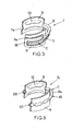
- the intermediate member 7 is a C-shaped, unitary, resilient member and extends in a circumferential direction, around a central axis Y, on an angle which may advantageously be comprised between 200° and 340°.
- Said intermediate member may be for instance molded out of plastic material (for instance polyamide or polyurethane) as a single piece, and may advantageously include :
- At least one of the end portions 9, and advantageously both end portions 9, include an abutment portion 10 which protrudes radially inwardly.
- the intermediate member includes a circumferential groove 11 which is open radially outwardly and which may for instance extend on the complete length of the intermediate member, between two open ends 11a at the free ends 12 of the C-shaped intermediate member.
- the intermediate member is sufficiently elastically clamped around the elastomer member so that said intermediate member be securely fixed on said elastomer member before the outer strength member is fitted on said elastomer body.
- the clamping force exerted by the intermediate member on opposite sides of the elastomer body may be comprised between 1 and 30 kg.
- the end portions 9 of the intermediate member respectively extend in the hydraulic chambers A, B, and the two abutment portions 10 of said intermediate member extend inwardly in said hydraulic chambers and are adapted to cooperate with the elastomer body on both sides of the inner strength member 2 for limiting relative radial movements of the inner and outer strength members in the direction of an axis X which is perpendicular to axes Y and Z.
- the end portions 9 of the intermediate member could be deprived of abutment portions 10.
- the elastomer body could possibly include abutment portions on one side or both sides of the inner strength member 2 in the direction of axis X.
- the free ends 12 of said intermediate member are preferably positioned on both sides of the radial arm 15 of the elastomer body, close to said radial arm, and the open ends 11a of the groove 11, which are in the form of V-shaped notches, open circumferentially and radially in the hydraulic chambers A, B in the vicinity of said axial arm 15.
- the upper and lower rims 17 of the end portions 9 are clamped between the bushings 6 of the rigid armature 5 and the outer strength member 3.
- the metal armature 5 also includes two axial struts 16 which connect together to two bushings 6 and which are over-molded respectively by the two radial arms 14, 15.
- the connecting portion 8 of the intermediate member is clamped between the outer strength member 3 and the axial strut 16 which is over-molded by the first radial arm 14 of the elastomer body.
- the second embodiment of the invention is identical to the first embodiment, except for the intermediate member 7, in which the groove 11 which partially bounds the throttled passage C, forms sinuosities 18 in one or in both of the end portions 9 of said intermediate member 7.
- the third embodiment of the invention is also identical to the first embodiment except for the intermediate member 7a, which includes a tube 19 made out of a resilient plastic material for instance and which entirely bounds the throttled passage C.
- the tube 19 forms by itself the connection portion 8a of the intermediate member, which is fitted in groove 13 of the elastomer body, and the plastic end portions 9 which were previously disclosed are over-molded on the tube 19.
- the two free ends of the tube which may be for instance level with the free ends 12 of the end portions 9, form the open ends 20 of the throttled passage C.
Landscapes
- Engineering & Computer Science (AREA)
- General Engineering & Computer Science (AREA)
- Mechanical Engineering (AREA)
- Combined Devices Of Dampers And Springs (AREA)
- Vehicle Body Suspensions (AREA)
Claims (12)
- Hülse zur hydraulischen Schwingungsdämpfung, umfassend:- ein steifes inneres Versteifungselement (2), welches sich parallel zu einer Mittelachse (Y) erstreckt,- ein rohrförmiges, steifes äußeres Versteifungselement (3), welches das innere Versteifungselement (2) und die Mittelachse (Y) umgibt,- einen Elastomerkörper (4), welcher das innere (2) und das äußere (3) Versteifungselement (2, 3) miteinander verbindet und wenigstens zwei Hydraulikkammern (A, B) ausbildet, die miteinander über einen gedrosselten Durchgang (C) in Verbindung stehen, wobei die hydraulischen Kammern (A, B) und der gedrosselte Durchgang (C) mit einer Flüssigkeit gefüllt sind, wobei der Elastomerkörper (4) einen ersten und einen zweiten Arm (14, 15) umfasst, welche die zwei hydraulischen Kammern (A, B) trennen, wobei der Elastomerkörper (4) auf einen steifen Anker (5) aufgegossen ist, welcher zwei ringförmige Buchsen aufweist, die miteinander durch wenigstens eine axiale Strebe (16) verbunden sind, die sich in dem ersten axialen Arm (14) des Elastomerkörpers erstreckt,- und ein Zwischenelement (7), wobei der Zwischenkörper ein C-förmiges, elastisches Element ist, das um den Elastomerkörper (4) aufgeschnappt ist und zwischen dem Elastomerkörper (4) und dem äußeren Versteifungselement (3) eingeklemmt ist, wobei das Zwischenelement umfasst:wobei das Zwischenelement (7) sich in eine Umfangsrichtung um die Mittelachse (Y) auf einem Winkel von mindestens 200° zwischen den zwei hydraulischen Kammern (A, B) erstreckt,* einen Verbindungsabschnitt (8), welcher radial zwischen der axialen Strebe (16) des ersten axialen Arms (14) und dem äußeren Versteifungselement (3) eingeklemmt ist,* und zwei Endabschnitte (9), welche miteinander verbunden sind durch den Verbindungsabschnitt und welche sich jeweils in die zwei hydraulischen Kammern (A, B) erstrecken,
wobei:das Elastomer des Weiteren eine Umfangsnut (13) umfasst, welche im ersten axialen Arm (14) ausgebildet ist,wobei das Zwischenelement (7) in der Nut (13) zwischen dem ersten und dem zweiten axialen Arm mit ausreichender Kraft aufgeschnappt ist, um fest auf dem Elastomerelement zu sitzen, bevor das äußere Versteifungselement (3) auf den Elastomerkörper aufgesteckt wird,
wobei das Zwischenelement (7) einstückig ist und teilweise oder zur Gänze einen gedrosselten Durchgang (C) entlang seiner Länge definiert. - Hülse zur hydraulischen Schwingungsdämpfung gemäß Anspruch 1, wobei das Zwischenelement (7) aus Kunststoffmaterial hergestellt ist.
- Hülse zur hydraulischen Schwingungsdämpfung gemäß Anspruch 1 oder Anspruch 2, wobei wenigstens einer der Endabschnitte (9) des Zwischenelements (7) einen Druckabschnitt (10) umfasst, welcher radial nach innen in eine der hydraulischen Kammern (A, B) vorragt und welcher ausgelegt ist, um mit dem Elastomerkörper (4) für begrenzte relative radiale Bewegungen der inneren und äußeren Versteifungselemente zusammen zu wirken.
- Hülse zur hydraulischen Schwingungsdämpfung gemäß einem beliebigen der Ansprüche 1 bis 3, wobei jeder der Endabschnitte (9) des Zwischenelements (7) radial zwischen den zwei Buchsen (6) des steifen Ankers und dem äußeren Versteifungselement (3) eingeklemmt ist.
- Hülse zur hydraulischen Schwingungsdämpfung gemäß einem beliebigen der vorangehenden Ansprüche, wobei jeder der zwei Endabschnitte (9) des Zwischenelements sich bis zu einem freien Ende erstreckt, welches nahe dem zweiten axialen Arm (15) des Elastomerkörpers liegt.
- Hülse zur hydraulischen Schwingungsdämpfung gemäß einem beliebigen der vorangehenden Ansprüche, wobei der Verbindungsabschnitt (8) des Zwischenelements fest in der Nut (13) sitzt.
- Hülse zur hydraulischen Schwingungsdämpfung gemäß einem beliebigen der vorangehenden Ansprüche, wobei die Endabschnitte (9) größer sind als der Verbindungsabschnitt (8) parallel zur Mittelachse (Y) und wobei der gedrosselte Durchgang C) Schlangenkrümmungen wenigstens in einem der Endabschnitte (9) ausbildet.
- Hülse zur hydraulischen Schwingungsdämpfung gemäß einem beliebigen der vorangehenden Ansprüche, wobei das Zwischenelement (7) aus einem Stück hergestellt ist und eine gekrümmte Nut (11) umfasst, welche in Richtung des äußeren Versteifungselements (3) offen ist, wobei das Zwischenelement (7) in engem Kontakt mit dem äußeren Versteifungselement (3) steht, so dass die Nut (11) und das äußere Versteifungselement (3) zur Gänze den gedrosselten Durchgang (C) umgrenzen.
- Hülse zur hydraulischen Schwingungsdämpfung gemäß einem beliebigen der vorangehenden Ansprüche, wobei das Zwischenelement ein Rohr (19) umfasst, welches zur Gänze den gedrosselten Durchgang umgrenzt.
- Hülse zur hydraulischen Schwingungsdämpfung gemäß Anspruch 9, wobei der Elastomerkörper (4) einen ersten und einen zweiten Arm (13, 14) umfasst, welche die zwei hydraulischen Kammern (A, B) trennen, wobei das Rohr (19) zwischen dem ersten axialen Arm (13) des Elastomerkörpers und dem äußeren Versteifungselement (3) eingeklemmt ist und wobei das Zwischenelement (7) des Weiteren zwei Endabschnitte (9) umfasst, welche miteinander durch das Rohr (19) verbunden sind und welche sich jeweils in die zwei hydraulischen Kammern (A, B) erstrecken.
- Hülse zur hydraulischen Schwingungsdämpfung gemäß Anspruch 10, wobei die Endabschnitte (9) des Zwischenelements über das Rohr (19) umspritzt sind.
- Hülse zur hydraulischen Schwingungsdämpfung gemäß einem beliebigen der vorangehenden Ansprüche, wobei sich das Zwischenelement (7) in eine Umfangsrichtung um die Mittelachse über einen Winkel von höchstens 340° erstreckt.
Applications Claiming Priority (2)
| Application Number | Priority Date | Filing Date | Title |
|---|---|---|---|
| US105555 | 1998-06-26 | ||
| US10/105,555 US6666437B2 (en) | 2002-03-25 | 2002-03-25 | Hydraulic anti-vibration sleeve |
Publications (2)
| Publication Number | Publication Date |
|---|---|
| EP1348885A1 EP1348885A1 (de) | 2003-10-01 |
| EP1348885B1 true EP1348885B1 (de) | 2008-04-09 |
Family
ID=27804334
Family Applications (1)
| Application Number | Title | Priority Date | Filing Date |
|---|---|---|---|
| EP03290678A Expired - Lifetime EP1348885B1 (de) | 2002-03-25 | 2003-03-18 | Hydraulische dämpfende Hülse |
Country Status (4)
| Country | Link |
|---|---|
| US (1) | US6666437B2 (de) |
| EP (1) | EP1348885B1 (de) |
| BR (1) | BR0300714B1 (de) |
| DE (1) | DE60320167T2 (de) |
Families Citing this family (21)
| Publication number | Priority date | Publication date | Assignee | Title |
|---|---|---|---|---|
| DE10153220A1 (de) * | 2001-10-31 | 2003-05-15 | Zf Lemfoerder Metallwaren Ag | Hydraulisch dämpfendes Gummilager |
| DE10315247B4 (de) * | 2003-04-03 | 2005-05-25 | Trelleborg Automotive Technical Centre Gmbh | Lagerbuchse mit Federelement |
| US8038132B2 (en) * | 2005-09-01 | 2011-10-18 | The Pullman Company | Hydraulic bushing |
| DE102006052917B4 (de) * | 2006-11-08 | 2012-07-19 | Vorwerk Autotec Gmbh & Co. Kg | Hydrolager mit Wegbegrenzung |
| US20090102218A1 (en) * | 2007-10-22 | 2009-04-23 | Freudenberg-Nok General Partnership | Body Mount Assembly With Hydraulic Damping Capability |
| US20100109214A1 (en) * | 2008-11-04 | 2010-05-06 | Gm Global Technology Operations, Inc. | Assembly For Transporting Pressurized Fluid and Method of Manufacture |
| GB0903868D0 (en) * | 2009-03-06 | 2009-04-22 | Siemens Magnet Technology Ltd | A magnetic resonance device |
| FR2954435B1 (fr) | 2009-12-22 | 2014-05-23 | Anvis Sd France Sas | Element fonctionnel hydro-elastique et articulation hydro-elastique |
| KR101316372B1 (ko) * | 2010-12-03 | 2013-10-08 | 현대자동차주식회사 | 액체봉입부시 |
| DE102012206621A1 (de) * | 2012-04-23 | 2013-10-24 | Zf Friedrichshafen Ag | Hydrolager mit einer als separates Bauteil hergestellten Dichtlippe |
| DE102012014318B4 (de) * | 2012-07-19 | 2016-10-20 | Anvis Deutschland Gmbh | Federfunktionsbauteil für ein hydroelastisches Lager und hydroelastisches Lager |
| US8820701B1 (en) * | 2012-11-28 | 2014-09-02 | Brunswick Corporation | Mounts, mounting arrangements, and methods of making mounting arrangements for supporting outboard motors with respect to marine vessels |
| WO2014179790A1 (en) * | 2013-05-03 | 2014-11-06 | Trelleborg Automotive Usa, Inc. | Hydraulic engine mount inertia track with at least two restrictions |
| DE102013008710A1 (de) * | 2013-05-22 | 2014-11-27 | Wilhelm Schröder GmbH | Hybridstopper eines Hydrolagers |
| JP5753225B2 (ja) * | 2013-06-17 | 2015-07-22 | 住友理工株式会社 | 防振装置 |
| RU2556235C1 (ru) * | 2013-12-30 | 2015-07-10 | Закрытое акционерное общество Научно-производственное внедренческое предприятие "Турбокон" | Виброизолирующий компенсатор трубопровода аварийной системы расхолаживания ядерного реактора подводной лодки |
| JP6444107B2 (ja) * | 2014-09-19 | 2018-12-26 | 山下ゴム株式会社 | 防振ブッシュ |
| FR3066002A1 (fr) | 2017-05-04 | 2018-11-09 | Sumiriko Industry France S.A.S. | Dispositif hydroelastique comportant une piece de blocage rigide deplacable |
| FR3066001B1 (fr) | 2017-05-04 | 2020-06-19 | Sumiriko Industry France S.A.S. | Dispositif hydroelastique comportant un systeme de blocage |
| US20190338826A1 (en) | 2018-05-07 | 2019-11-07 | Hutchinson Antivibration Systems, Inc. | Anti-vibration device |
| KR20230149367A (ko) * | 2022-04-19 | 2023-10-27 | 현대자동차주식회사 | 하이드로 부시 |
Family Cites Families (18)
| Publication number | Priority date | Publication date | Assignee | Title |
|---|---|---|---|---|
| JP2583212B2 (ja) * | 1985-05-27 | 1997-02-19 | 日産自動車株式会社 | 振動減衰装置 |
| JPH0193640A (ja) | 1987-10-05 | 1989-04-12 | Tokai Rubber Ind Ltd | 流体封入式円筒型マウント装置 |
| DE3800656A1 (de) * | 1988-01-13 | 1989-08-03 | Freudenberg Carl Fa | Hydraulisch daempfende huelsengummifeder |
| DE3909609A1 (de) * | 1989-03-23 | 1990-10-04 | Freudenberg Carl Fa | Huelsengummifeder |
| JPH03121327A (ja) * | 1989-10-02 | 1991-05-23 | Tokai Rubber Ind Ltd | 流体封入式筒型マウント装置 |
| US5040774A (en) * | 1990-04-09 | 1991-08-20 | The Pullman Company | Hydraulic damping bushing |
| JP2569977B2 (ja) | 1990-07-27 | 1997-01-08 | 豊田合成株式会社 | 液封入筒状防振ブッシュの製造方法 |
| JPH0442937U (de) * | 1990-08-09 | 1992-04-13 | ||
| JPH0565933A (ja) | 1991-09-06 | 1993-03-19 | Bridgestone Corp | 防振装置 |
| DE4332480C2 (de) | 1993-09-24 | 1996-02-15 | Boge Gmbh | Hydraulisch dämpfendes Gummilager |
| FR2712652B1 (fr) | 1993-11-16 | 1996-01-26 | Hutchinson | Perfectionnements apportés aux manchons antivibratoires hydrauliques. |
| US5397112A (en) | 1994-05-05 | 1995-03-14 | The Pullman Company | Fluid-filled elastomeric suspension bushing |
| US5702094A (en) * | 1994-08-10 | 1997-12-30 | Btr Antivibration Systems, Inc. | Fluid damped bushing with encapsulated window metal |
| US5413319A (en) * | 1994-08-10 | 1995-05-09 | Gencorp Inc. | Fluid damped bushing |
| DE19527260A1 (de) * | 1995-07-26 | 1997-01-30 | Boge Gmbh | Hydraulisch dämpfendes Motorlager |
| ES2155307B1 (es) | 1996-09-26 | 2001-12-16 | Boge Gmbh | "cojinete amortiguador hidraulico de caucho". |
| DE19919863B4 (de) * | 1999-04-30 | 2004-07-08 | ZF Lemförder Metallwaren AG | Gummilager mit radialer Wegbegrenzung und Dämpfungsmittelkanal |
| US6513801B1 (en) * | 2002-07-24 | 2003-02-04 | The Pullman Company | Hinged/split reinforced clam shell bushing |
-
2002
- 2002-03-25 US US10/105,555 patent/US6666437B2/en not_active Expired - Lifetime
-
2003
- 2003-03-18 EP EP03290678A patent/EP1348885B1/de not_active Expired - Lifetime
- 2003-03-18 DE DE60320167T patent/DE60320167T2/de not_active Expired - Lifetime
- 2003-03-24 BR BRPI0300714-6B1A patent/BR0300714B1/pt not_active IP Right Cessation
Also Published As
| Publication number | Publication date |
|---|---|
| EP1348885A1 (de) | 2003-10-01 |
| DE60320167T2 (de) | 2009-05-14 |
| DE60320167D1 (de) | 2008-05-21 |
| US20030178754A1 (en) | 2003-09-25 |
| BR0300714A (pt) | 2004-09-08 |
| US6666437B2 (en) | 2003-12-23 |
| BR0300714B1 (pt) | 2013-10-08 |
Similar Documents
| Publication | Publication Date | Title |
|---|---|---|
| US6666437B2 (en) | Hydraulic anti-vibration sleeve | |
| KR101363089B1 (ko) | 차량의 섀시에 배치된 부품들의 관절형 연결을 위한 연결부 | |
| US6729611B2 (en) | Antivibration sleeve and a motor vehicle including such a sleeve | |
| JP4560376B2 (ja) | スタビライザブッシュ | |
| EP2502764B1 (de) | Stabilisatorelement für eine Fahrzeugaufhängung und Herstellungsverfahren dafür | |
| JPH09175139A (ja) | スタビライザの端部を部材に結合する取付け部 | |
| JP5230390B2 (ja) | 防振連結ロッド | |
| JPH0954U (ja) | 液体式防振支持スリーブ | |
| JP5095577B2 (ja) | 防振連結ロッド | |
| EP2242660A2 (de) | Hydro-buchse | |
| KR102522852B1 (ko) | 조인트 및 상기 조인트의 제조 방법 | |
| CA3035735C (en) | Stabilizer and assembling method therefor | |
| US6354614B1 (en) | Link assembly for motor vehicle suspension | |
| CZ218598A3 (cs) | Zařízení pro podepření a zajištění polohy stabilizační tyče motorového vozidla | |
| JPH10110726A (ja) | 油圧減衰弾性軸受 | |
| JPH0610940A (ja) | 複合材料製駆動軸 | |
| JP2009115109A (ja) | 防振連結ロッド | |
| EP0995928A2 (de) | Hydroelastisches Gelenk | |
| KR20150008815A (ko) | 서스펜션 스트럿에 스태빌라이저를 고정하는 유지 장치 및 그러한 유지 장치를 포함하는 휠 서스펜션 | |
| JP2008095861A (ja) | 防振ブッシュ及びリンク部材 | |
| JP4261587B2 (ja) | 防振ブッシュ | |
| US20060186629A1 (en) | Wheel suspension | |
| KR102563489B1 (ko) | 양단 버링 암 어셈블리 | |
| US20040164469A1 (en) | Hydraulic antivibration pivot with axial stops, vehicle equipped with such a pivot, and method of producing such a pivot | |
| JPS5952303B2 (ja) | Frp板ばね装置用目玉部材 |
Legal Events
| Date | Code | Title | Description |
|---|---|---|---|
| PUAI | Public reference made under article 153(3) epc to a published international application that has entered the european phase |
Free format text: ORIGINAL CODE: 0009012 |
|
| AK | Designated contracting states |
Kind code of ref document: A1 Designated state(s): AT BE BG CH CY CZ DE DK EE ES FI FR GB GR HU IE IT LI LU MC NL PT RO SE SI SK TR |
|
| AX | Request for extension of the european patent |
Extension state: AL LT LV MK |
|
| 17P | Request for examination filed |
Effective date: 20031006 |
|
| AKX | Designation fees paid |
Designated state(s): DE ES FR GB IT |
|
| 17Q | First examination report despatched |
Effective date: 20050224 |
|
| 17Q | First examination report despatched |
Effective date: 20050224 |
|
| GRAP | Despatch of communication of intention to grant a patent |
Free format text: ORIGINAL CODE: EPIDOSNIGR1 |
|
| GRAS | Grant fee paid |
Free format text: ORIGINAL CODE: EPIDOSNIGR3 |
|
| GRAA | (expected) grant |
Free format text: ORIGINAL CODE: 0009210 |
|
| AK | Designated contracting states |
Kind code of ref document: B1 Designated state(s): DE ES FR GB IT |
|
| REG | Reference to a national code |
Ref country code: GB Ref legal event code: FG4D |
|
| REF | Corresponds to: |
Ref document number: 60320167 Country of ref document: DE Date of ref document: 20080521 Kind code of ref document: P |
|
| PG25 | Lapsed in a contracting state [announced via postgrant information from national office to epo] |
Ref country code: ES Free format text: LAPSE BECAUSE OF FAILURE TO SUBMIT A TRANSLATION OF THE DESCRIPTION OR TO PAY THE FEE WITHIN THE PRESCRIBED TIME-LIMIT Effective date: 20080720 |
|
| ET | Fr: translation filed | ||
| PLBE | No opposition filed within time limit |
Free format text: ORIGINAL CODE: 0009261 |
|
| STAA | Information on the status of an ep patent application or granted ep patent |
Free format text: STATUS: NO OPPOSITION FILED WITHIN TIME LIMIT |
|
| 26N | No opposition filed |
Effective date: 20090112 |
|
| GBPC | Gb: european patent ceased through non-payment of renewal fee |
Effective date: 20090318 |
|
| PG25 | Lapsed in a contracting state [announced via postgrant information from national office to epo] |
Ref country code: GB Free format text: LAPSE BECAUSE OF NON-PAYMENT OF DUE FEES Effective date: 20090318 |
|
| REG | Reference to a national code |
Ref country code: FR Ref legal event code: PLFP Year of fee payment: 13 |
|
| REG | Reference to a national code |
Ref country code: FR Ref legal event code: PLFP Year of fee payment: 14 |
|
| REG | Reference to a national code |
Ref country code: DE Ref legal event code: R082 Ref document number: 60320167 Country of ref document: DE Representative=s name: MAIKOWSKI & NINNEMANN PATENTANWAELTE PARTNERSC, DE Ref country code: DE Ref legal event code: R081 Ref document number: 60320167 Country of ref document: DE Owner name: HUTCHINSON ANTIVIBRATION SYSTEMS INC., GRAND R, US Free format text: FORMER OWNER: PAULSTRA CRC, GRAND RAPIDS, MICH., US |
|
| REG | Reference to a national code |
Ref country code: FR Ref legal event code: CA Effective date: 20161110 Ref country code: FR Ref legal event code: CD Owner name: HUTCHINSON ANTIVIBRATION SYSTEMS, INC., US Effective date: 20161110 |
|
| REG | Reference to a national code |
Ref country code: FR Ref legal event code: PLFP Year of fee payment: 15 |
|
| REG | Reference to a national code |
Ref country code: FR Ref legal event code: PLFP Year of fee payment: 16 |
|
| PGFP | Annual fee paid to national office [announced via postgrant information from national office to epo] |
Ref country code: DE Payment date: 20180309 Year of fee payment: 16 |
|
| PGFP | Annual fee paid to national office [announced via postgrant information from national office to epo] |
Ref country code: FR Payment date: 20180327 Year of fee payment: 16 Ref country code: IT Payment date: 20180309 Year of fee payment: 16 |
|
| REG | Reference to a national code |
Ref country code: DE Ref legal event code: R119 Ref document number: 60320167 Country of ref document: DE |
|
| PG25 | Lapsed in a contracting state [announced via postgrant information from national office to epo] |
Ref country code: DE Free format text: LAPSE BECAUSE OF NON-PAYMENT OF DUE FEES Effective date: 20191001 |
|
| PG25 | Lapsed in a contracting state [announced via postgrant information from national office to epo] |
Ref country code: FR Free format text: LAPSE BECAUSE OF NON-PAYMENT OF DUE FEES Effective date: 20190331 Ref country code: IT Free format text: LAPSE BECAUSE OF NON-PAYMENT OF DUE FEES Effective date: 20190318 |