US8038132B2 - Hydraulic bushing - Google Patents
Hydraulic bushing Download PDFInfo
- Publication number
- US8038132B2 US8038132B2 US11/507,313 US50731306A US8038132B2 US 8038132 B2 US8038132 B2 US 8038132B2 US 50731306 A US50731306 A US 50731306A US 8038132 B2 US8038132 B2 US 8038132B2
- Authority
- US
- United States
- Prior art keywords
- insert
- outer tube
- bushing
- disposed
- elastomeric
- Prior art date
- Legal status (The legal status is an assumption and is not a legal conclusion. Google has not performed a legal analysis and makes no representation as to the accuracy of the status listed.)
- Active, expires
Links
- 239000012530 fluid Substances 0.000 claims description 50
- 230000000694 effects Effects 0.000 description 5
- 230000006835 compression Effects 0.000 description 4
- 238000007906 compression Methods 0.000 description 4
- 230000014759 maintenance of location Effects 0.000 description 3
- 238000006073 displacement reaction Methods 0.000 description 2
- 230000009286 beneficial effect Effects 0.000 description 1
- 238000002955 isolation Methods 0.000 description 1
- 230000010355 oscillation Effects 0.000 description 1
- 238000007789 sealing Methods 0.000 description 1
- 239000000725 suspension Substances 0.000 description 1
Images


Classifications
-
- F—MECHANICAL ENGINEERING; LIGHTING; HEATING; WEAPONS; BLASTING
- F16—ENGINEERING ELEMENTS AND UNITS; GENERAL MEASURES FOR PRODUCING AND MAINTAINING EFFECTIVE FUNCTIONING OF MACHINES OR INSTALLATIONS; THERMAL INSULATION IN GENERAL
- F16F—SPRINGS; SHOCK-ABSORBERS; MEANS FOR DAMPING VIBRATION
- F16F9/00—Springs, vibration-dampers, shock-absorbers, or similarly-constructed movement-dampers using a fluid or the equivalent as damping medium
- F16F9/32—Details
-
- F—MECHANICAL ENGINEERING; LIGHTING; HEATING; WEAPONS; BLASTING
- F16—ENGINEERING ELEMENTS AND UNITS; GENERAL MEASURES FOR PRODUCING AND MAINTAINING EFFECTIVE FUNCTIONING OF MACHINES OR INSTALLATIONS; THERMAL INSULATION IN GENERAL
- F16F—SPRINGS; SHOCK-ABSORBERS; MEANS FOR DAMPING VIBRATION
- F16F5/00—Liquid springs in which the liquid works as a spring by compression, e.g. combined with throttling action; Combinations of devices including liquid springs
-
- F—MECHANICAL ENGINEERING; LIGHTING; HEATING; WEAPONS; BLASTING
- F16—ENGINEERING ELEMENTS AND UNITS; GENERAL MEASURES FOR PRODUCING AND MAINTAINING EFFECTIVE FUNCTIONING OF MACHINES OR INSTALLATIONS; THERMAL INSULATION IN GENERAL
- F16F—SPRINGS; SHOCK-ABSORBERS; MEANS FOR DAMPING VIBRATION
- F16F13/00—Units comprising springs of the non-fluid type as well as vibration-dampers, shock-absorbers, or fluid springs
- F16F13/04—Units comprising springs of the non-fluid type as well as vibration-dampers, shock-absorbers, or fluid springs comprising both a plastics spring and a damper, e.g. a friction damper
- F16F13/06—Units comprising springs of the non-fluid type as well as vibration-dampers, shock-absorbers, or fluid springs comprising both a plastics spring and a damper, e.g. a friction damper the damper being a fluid damper, e.g. the plastics spring not forming a part of the wall of the fluid chamber of the damper
- F16F13/08—Units comprising springs of the non-fluid type as well as vibration-dampers, shock-absorbers, or fluid springs comprising both a plastics spring and a damper, e.g. a friction damper the damper being a fluid damper, e.g. the plastics spring not forming a part of the wall of the fluid chamber of the damper the plastics spring forming at least a part of the wall of the fluid chamber of the damper
- F16F13/14—Units of the bushing type, i.e. loaded predominantly radially
- F16F13/1409—Units of the bushing type, i.e. loaded predominantly radially characterised by buffering features or stoppers
-
- F—MECHANICAL ENGINEERING; LIGHTING; HEATING; WEAPONS; BLASTING
- F16—ENGINEERING ELEMENTS AND UNITS; GENERAL MEASURES FOR PRODUCING AND MAINTAINING EFFECTIVE FUNCTIONING OF MACHINES OR INSTALLATIONS; THERMAL INSULATION IN GENERAL
- F16F—SPRINGS; SHOCK-ABSORBERS; MEANS FOR DAMPING VIBRATION
- F16F13/00—Units comprising springs of the non-fluid type as well as vibration-dampers, shock-absorbers, or fluid springs
- F16F13/04—Units comprising springs of the non-fluid type as well as vibration-dampers, shock-absorbers, or fluid springs comprising both a plastics spring and a damper, e.g. a friction damper
- F16F13/06—Units comprising springs of the non-fluid type as well as vibration-dampers, shock-absorbers, or fluid springs comprising both a plastics spring and a damper, e.g. a friction damper the damper being a fluid damper, e.g. the plastics spring not forming a part of the wall of the fluid chamber of the damper
- F16F13/08—Units comprising springs of the non-fluid type as well as vibration-dampers, shock-absorbers, or fluid springs comprising both a plastics spring and a damper, e.g. a friction damper the damper being a fluid damper, e.g. the plastics spring not forming a part of the wall of the fluid chamber of the damper the plastics spring forming at least a part of the wall of the fluid chamber of the damper
- F16F13/14—Units of the bushing type, i.e. loaded predominantly radially
- F16F13/1463—Units of the bushing type, i.e. loaded predominantly radially characterised by features of passages between working chambers
-
- F—MECHANICAL ENGINEERING; LIGHTING; HEATING; WEAPONS; BLASTING
- F16—ENGINEERING ELEMENTS AND UNITS; GENERAL MEASURES FOR PRODUCING AND MAINTAINING EFFECTIVE FUNCTIONING OF MACHINES OR INSTALLATIONS; THERMAL INSULATION IN GENERAL
- F16F—SPRINGS; SHOCK-ABSORBERS; MEANS FOR DAMPING VIBRATION
- F16F13/00—Units comprising springs of the non-fluid type as well as vibration-dampers, shock-absorbers, or fluid springs
- F16F13/04—Units comprising springs of the non-fluid type as well as vibration-dampers, shock-absorbers, or fluid springs comprising both a plastics spring and a damper, e.g. a friction damper
- F16F13/06—Units comprising springs of the non-fluid type as well as vibration-dampers, shock-absorbers, or fluid springs comprising both a plastics spring and a damper, e.g. a friction damper the damper being a fluid damper, e.g. the plastics spring not forming a part of the wall of the fluid chamber of the damper
- F16F13/08—Units comprising springs of the non-fluid type as well as vibration-dampers, shock-absorbers, or fluid springs comprising both a plastics spring and a damper, e.g. a friction damper the damper being a fluid damper, e.g. the plastics spring not forming a part of the wall of the fluid chamber of the damper the plastics spring forming at least a part of the wall of the fluid chamber of the damper
- F16F13/14—Units of the bushing type, i.e. loaded predominantly radially
- F16F13/1481—Units of the bushing type, i.e. loaded predominantly radially characterised by features of plastic springs, e.g. presence of cavities or stiffeners; characterised by features of flexible walls of equilibration chambers, i.e. membranes
Definitions
- the present invention relates to a hydraulic bushing. More particularly, the present invention relates to a hydraulic bushing that incorporates a two ring intermediate tube.
- Hydraulic bushings typically used in automobile suspensions are expected to damp low frequency large displacement oscillations as well as contribute to high frequency acoustic isolation from relatively small displacements. Hydraulic bushings typically have two hydraulic chambers connected by a channel. The resonance of the fluid in the channel creates a mass damper effect.
- a single piece intermediate tube is utilized in some designs to improve the durability of the bushing and to separate the working part of the elastomeric bushing where the loads are taken from the outer part of the elastomeric bushing where the channels are formed and the fluid sealing is provided for the fluid within the bushing.
- the intermediate tube is only needed at the ends of the bushing and the center portion of the intermediate tube is used predominantly to provide an interconnection between the two end portions.
- the single piece intermediate tube is an expensive component that presents various difficulties during the assembly of the hydraulic bushing.
- a hydraulic bushing which has two hydraulic chambers connected by a channel.
- the resonance of the fluid in the channel creates a mass damper effect.
- the hydraulic bushing uses two very short tubes which separate the inner or working part of the elastomeric bushing where the loads are taken from the outer part of the elastomeric bushing where the fluid within the channels and hydraulic chambers is sealed.
- the hydraulic bushing includes a retention system which maintains the position of the two short tubes within the hydraulic bushing.
- FIG. 1 is a perspective view of a hydraulic bushing assembly in accordance with one embodiment of the present disclosure
- FIG. 2 is a cross-sectional view of the hydraulic bushing assembly illustrated in FIG. 1 ;
- FIG. 3 is a perspective view of the insert in position on the elastomeric bushing illustrated in FIGS. 1 and 2 ;
- FIG. 4 is a perspective view of the insert illustrated in FIGS. 1-3 ;
- FIG. 5 is a cross-sectional view of a hydraulic bushing assembly in accordance with another embodiment of the present disclosure.
- FIG. 6 is a perspective view of the intermediate tubes and elastomeric bushing illustrated in FIG. 5 ;
- FIG. 7 is a perspective view of the insert illustrated in FIG. 5 ;
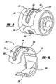
- FIG. 8 is an end view of a hydraulic bushing assembly in accordance with another embodiment of the disclosure.
- FIG. 9 is a perspective view of the insert and the elastomeric bushing illustrated in FIG. 8 ;
- FIG. 10 is a perspective view of the insert illustrated in FIG. 8 .
- Hydraulic bushing assembly 10 comprises an inner tube 12 , an elastomeric bushing 14 , a pair of inserts 16 , a pair of intermediate tubes 18 and an outer tube 20 .
- Elastomeric bushing 14 is located over inner tube 12 and can be secured to inner tube 12 by compression of elastomeric bushing 14 and the associated friction between elastomeric bushing 14 and inner tube 12 ; by being bonded to inner tube 12 ; or by any other means known in the art.
- Elastomeric bushing 14 defines a pair of voids 30 which with inserts 16 define a pair of fluid chambers 32 .
- Elastomeric bushing 14 also defines a pocket 34 within which inserts 16 are located.
- Each insert 16 is identical and the two inserts are positioned adjacent each other surrounding elastomeric bushing 14 .
- Each insert defines a bump stop 36 and a fluid channel 38 .
- Bump stop 36 limits the radial movement of inner tube 12 with respect to inserts 16 and outer tube 20 .
- Channel 38 includes a circumferential portion 40 , an axial portion 42 and a radial portion 44 .
- Radial portion 44 is open to one of the fluid chambers 32 and circumferential portion 40 is in communication with circumferential portion 40 on the adjacent insert 16 which has its radial portion 44 in communication with the other fluid chamber 32 .
- one fluid chamber 32 is in fluid communication with the opposite fluid chamber 32 through radial portion 44 of one insert 16 , axial portion 42 of the one insert 16 , circumferential portion 40 of the one insert 16 , circumferential portion 40 of the other insert 16 , axial portion 42 of the other insert 16 and radial portion 44 of the other insert 16 .
- the flow of the fluid between chambers 32 through channels 38 creates a mass damper effect for hydraulic bushing assembly 10 .
- Outer tube 20 is positioned over inserts 16 and elastomeric bushing 14 .
- Outer tube 20 closes channels 38 of inserts 16 and elastomeric bushing 14 engages the inside surface of outer tube 20 to provide a seal for the fluid located within fluid chambers 32 and channels 38 .
- the pair of intermediate tubes 18 are located within opposite end of elastomeric bushing 14 between inner tube 12 and outer tube 20 .
- the ends of outer tube 20 are curled over as shown at 46 to trap each intermediate tube 18 between the curled end 46 and inserts 16 .
- Intermediate tubes 18 separate the inner or working part of elastomeric bushing 14 where the loads are taken from the outer part of elastomeric bushing 14 which with the inside surface of outer tube 20 provides a fluid seal for hydraulic bushing assembly 10 .
- Hydraulic bushing assembly 110 in accordance with another embodiment of the present disclosure is illustrated.
- Hydraulic bushing assembly 110 comprises inner tube 12 , an elastomeric bushing 114 , a pair of inserts 116 , a pair of intermediate tubes 118 and an outer tube 120 .
- Hydraulic bushing assembly 110 is the same as hydraulic bushing assembly 10 except that the curled ends shown at 46 for hydraulic bushing assembly 10 have been replaced with a retention system described below.
- Elastomeric bushing 114 is located over inner tube 12 and can be secured to inner tube 12 by compression of elastomeric bushing 114 and the associated friction between elastomeric bushing 114 and inner tube 12 ; by being bonded to inner tube 12 ; or by any other means known in the art.
- Elastomeric bushing 114 defines a pair of voids 130 which with inserts 116 define a pair of fluid chambers 132 .
- Elastomeric bushing 114 also defines a pocket 134 within which inserts 116 are located.
- Each insert 116 is identical and the two inserts are positioned adjacent each other surrounding elastomeric bushing 114 .
- Each insert defines a bump stop 136 and a fluid channel 138 .
- Bump stop 136 limits the radial movement of inner tube 12 with respect to inserts 116 and outer tube 120 .
- Channel 138 includes a circumferential portion 140 , an axial portion 142 and a radial portion 144 .
- Radial portion 144 is open to one of the fluid chambers 132 and circumferential portion 140 is in communication with circumferential portion 140 on the adjacent insert 116 which has its radial portion 144 in communication with the other fluid chamber 132 .
- one fluid chamber 132 is in fluid communication with the opposite fluid chamber 132 through radial portion 144 of one insert 116 , axial portion 142 of the one insert 116 , circumferential portion 140 of the one insert 116 , circumferential portion 140 of the other insert 116 , axial portion 142 of the other insert 116 and radial portion 144 of the other insert 116 .
- the flow of the fluid between chambers 132 through channels 138 creates a mass damper effect for hydraulic bushing assembly 110 .
- Outer tube 120 is positioned over inserts 116 and elastomeric bushing 114 . Outer tube 120 closes channels 138 of inserts 116 and elastomeric bushing 114 engages the inside surface of outer tube 120 to provide a seal for the fluid located within fluid chambers 132 and channels 138 .
- the pair of intermediate tubes 118 are located within opposite end of elastomeric bushing 114 between inner tube 12 and outer tube 120 .
- Each intermediate tube 118 comprises a pair of tubular sections 150 which form a female portion 152 of a toggle lock 154 .
- Each insert 116 defines a male portion 156 of toggle lock 154 at each side of each insert 116 .
- male portion 156 of toggle lock 154 is positioned within female portion 152 of toggle lock 154 .
- Intermediate tubes 118 separates the inner or working part of elastomeric bushing 114 where the loads are taken from the outer part of elastomeric bushing 114 which with the inside surface of outer tube 120 provides a fluid seal for hydraulic bushing assembly 110 .
- Hydraulic bushing assembly 210 in accordance with another embodiment of the present disclosure is illustrated.
- Hydraulic bushing assembly 210 comprises inner tube 12 , an elastomeric bushing 214 , an insert 216 , the pair of intermediate tubes 18 and outer tube 20 .
- Hydraulic bushing assembly 210 is the same as hydraulic bushing assembly 10 except that the two inserts 16 have been replaced with a single piece insert 216 as described below.
- Elastomeric bushing 214 is located over inner tube 12 and can be secured to inner tube 12 by compression of elastomeric bushing 214 and the associated friction between elastomeric bushing 214 and inner tube 12 ; by being bonded to inner tube 12 ; or by any other means known in the art.
- Elastomeric bushing 214 defines a pair of voids 230 which with inserts 216 define a pair of fluid chambers 232 .
- Elastomeric bushing 214 also defines a pocket 234 within which insert 216 is located.
- Insert 216 is a single piece component which defines two halves interconnected by a living hinge 236 .
- Living hinge 236 is a thin-walled portion of insert 216 .
- Living hinge 236 allows insert 216 to flex through a large arc thus forming a near zero cost hinge. The flexing of living hinge 236 allows for the assembly of insert 216 over elastomeric bushing 214 .
- Insert 216 defines a pair of bump stops 238 and a fluid channel 240 . Bump stops 238 limit the radial movement of inner tube 12 with respect to insert 216 and outer tube 20 .
- Channel 240 includes a circumferential portion 242 , a pair of axial portions 244 and a pair of radial portions 246 .
- Radial portions 246 are each open to respective fluid chambers 232 .
- one fluid chamber 232 is in fluid communication with the opposite fluid chamber 232 through one of the radial portions 246 , through one of the axial portions 244 , through circumferential portion 242 , through the other axial portion 244 and through the other radial portion 246 .
- the flow of fluid between one chamber 232 , through channel 240 creates a mass damper effect for hydraulic bushing assembly 210 .
- Outer tube 20 is positioned over inserts 216 and elastomeric bushing 214 .
- Outer tube 20 closes channels 240 of insert 216 and elastomeric bushing 214 engages the inside surface of outer tube 20 to provide a seal for the fluid located within fluid chambers 232 and channel 240 .
- the pair of intermediate tubes 18 are located within opposite end of elastomeric bushing 214 between inner tube 12 and outer tube 20 .
- the ends of outer tube 20 are curled over as shown at 46 to trap each intermediate tube 18 between the curled end 46 and insert 216 .
- Intermediate tubes 18 separate the inner or working part of elastomeric bushing 214 where the loads are taken from the outer part of elastomeric bushing 214 which with the inside surface of outer tube 20 provides a fluid seal for hydraulic bushing assembly 210 .
- the inertia track is the flow path or channel 240 that resonates within hydraulic bushing assembly 210 .
- Channel 240 is formed into the outside diameter of insert 216 and then closed by outer tube 20 or 120 . Due to the compression of elastomeric bushing 214 , the energization of elastomeric bushing 214 applies a force to the ends of insert 216 as illustrated by arrows 250 in FIG. 8 . This force acts similar to the wheel cylinder in a leading/trailing drum brake. A relatively small force is mechanically magnified in this way to press insert 216 hard against outer tube 20 or outer tube 120 . In addition, the approximately forty-five degree angle on the interface between insert 216 and elastomeric bushing 214 as illustrated at 252 in FIG. 9 , is beneficial in that it enhances the distance that elastomeric bushing 214 can act through.
Landscapes
- Engineering & Computer Science (AREA)
- General Engineering & Computer Science (AREA)
- Mechanical Engineering (AREA)
- Combined Devices Of Dampers And Springs (AREA)
- Vehicle Body Suspensions (AREA)
- Springs (AREA)
- Valves And Accessory Devices For Braking Systems (AREA)
Abstract
Description
Claims (7)
Priority Applications (8)
| Application Number | Priority Date | Filing Date | Title |
|---|---|---|---|
| US11/507,313 US8038132B2 (en) | 2005-09-01 | 2006-08-21 | Hydraulic bushing |
| PCT/US2006/033728 WO2007027695A2 (en) | 2005-09-01 | 2006-08-29 | Hydraulic bushing |
| JP2008529197A JP4937264B2 (en) | 2005-09-01 | 2006-08-29 | Hydraulic bush |
| DE112006002321.7T DE112006002321B4 (en) | 2005-09-01 | 2006-08-29 | hydraulic jack |
| GB0803364A GB2442926B (en) | 2005-09-01 | 2006-08-29 | Hydraulic bushing assembly |
| CN2006800316807A CN101253347B (en) | 2005-09-01 | 2006-08-29 | Hydraulic bushing |
| BRPI0616117-0A BRPI0616117B1 (en) | 2005-09-01 | 2006-08-29 | HYDRAULIC BUSHING ASSEMBLY |
| KR1020087004948A KR101273546B1 (en) | 2005-09-01 | 2008-02-28 | hydraulic bushing |
Applications Claiming Priority (2)
| Application Number | Priority Date | Filing Date | Title |
|---|---|---|---|
| US71354305P | 2005-09-01 | 2005-09-01 | |
| US11/507,313 US8038132B2 (en) | 2005-09-01 | 2006-08-21 | Hydraulic bushing |
Publications (2)
| Publication Number | Publication Date |
|---|---|
| US20070045918A1 US20070045918A1 (en) | 2007-03-01 |
| US8038132B2 true US8038132B2 (en) | 2011-10-18 |
Family
ID=39956033
Family Applications (1)
| Application Number | Title | Priority Date | Filing Date |
|---|---|---|---|
| US11/507,313 Active 2029-09-14 US8038132B2 (en) | 2005-09-01 | 2006-08-21 | Hydraulic bushing |
Country Status (8)
| Country | Link |
|---|---|
| US (1) | US8038132B2 (en) |
| JP (1) | JP4937264B2 (en) |
| KR (1) | KR101273546B1 (en) |
| CN (1) | CN101253347B (en) |
| BR (1) | BRPI0616117B1 (en) |
| DE (1) | DE112006002321B4 (en) |
| GB (1) | GB2442926B (en) |
| WO (1) | WO2007027695A2 (en) |
Cited By (10)
| Publication number | Priority date | Publication date | Assignee | Title |
|---|---|---|---|---|
| US20100225321A1 (en) * | 2009-03-06 | 2010-09-09 | Marcel Jan Marie Kruip | Magnetic resonance device |
| US8820701B1 (en) * | 2012-11-28 | 2014-09-02 | Brunswick Corporation | Mounts, mounting arrangements, and methods of making mounting arrangements for supporting outboard motors with respect to marine vessels |
| US9133903B2 (en) | 2013-03-15 | 2015-09-15 | The Pullman Company | Hydroelastic fluids for fluid filled elastomeric damping devices |
| US20160290433A1 (en) * | 2013-03-29 | 2016-10-06 | Yamashita Rubber Co., Ltd. | Liquid-sealed vibration prevention device |
| US9976620B2 (en) * | 2015-10-05 | 2018-05-22 | The Pullman Company | System and method for a bushing assembly having radial rubber stopper |
| CN108343701A (en) * | 2017-01-23 | 2018-07-31 | 株洲时代新材料科技股份有限公司 | A kind of hydraulic bushing |
| US10047820B2 (en) | 2015-04-10 | 2018-08-14 | Anand Nvh Products Inc. | Fluid-filled, vibration damping bushing assembly and method of manufacturing the same |
| CN111706639A (en) * | 2020-05-27 | 2020-09-25 | 株洲时代新材料科技股份有限公司 | Hydraulic composite bushing, runner for hydraulic composite bushing and forming method of runner |
| US11028894B2 (en) * | 2018-03-30 | 2021-06-08 | Sumitomo Riko Company Limited | Tubular vibration-damping device |
| US11434974B2 (en) * | 2019-07-22 | 2022-09-06 | Sumitomo Riko Company Limited | Vibration absorber and method for producing a vibration absorber |
Families Citing this family (20)
| Publication number | Priority date | Publication date | Assignee | Title |
|---|---|---|---|---|
| JP2006022907A (en) * | 2004-07-08 | 2006-01-26 | Tokai Rubber Ind Ltd | Liquid-sealed vibration-isolation bush |
| DE102006032633A1 (en) * | 2006-07-13 | 2008-01-17 | Zf Friedrichshafen Ag | Bush bearing used in the vehicle industry comprises a sealing lip which is structured so that is oscillates corresponding to the damping volume displaced by deflecting a bearing body in the radial direction |
| DE102008040548B4 (en) * | 2008-07-18 | 2013-01-17 | Zf Friedrichshafen Ag | Hydraulically damping bush bearing |
| US20130032442A1 (en) * | 2010-01-25 | 2013-02-07 | Lotus FI Team Limited | Fluid Inerter |
| WO2012054774A2 (en) | 2010-10-20 | 2012-04-26 | Penske Racing Shocks | Shock absorber with inertance |
| DE102012206621A1 (en) * | 2012-04-23 | 2013-10-24 | Zf Friedrichshafen Ag | Hydraulic bearing with a sealing lip produced as a separate component |
| DE102012014318B4 (en) | 2012-07-19 | 2016-10-20 | Anvis Deutschland Gmbh | Spring function component for a hydroelastic bearing and hydroelastic bearing |
| JP6126889B2 (en) * | 2013-03-29 | 2017-05-10 | 山下ゴム株式会社 | Liquid seal type vibration isolator |
| DE102016001507B4 (en) * | 2016-02-10 | 2020-06-18 | Anvis Deutschland Gmbh | Vibration damper |
| US10145434B2 (en) * | 2016-05-19 | 2018-12-04 | The Boeing Company | Translational inerter assembly and method for damping movement of a flight control surface |
| US10088006B2 (en) * | 2016-05-19 | 2018-10-02 | The Boeing Company | Rotational inerter and method for damping an actuator |
| US10107347B2 (en) * | 2016-05-19 | 2018-10-23 | The Boeing Company | Dual rack and pinion rotational inerter system and method for damping movement of a flight control surface of an aircraft |
| CN108150588A (en) * | 2016-12-02 | 2018-06-12 | 株洲时代新材料科技股份有限公司 | A kind of rail traffic hydraulic bushing |
| CN106704437A (en) * | 2017-03-01 | 2017-05-24 | 天纳克汽车工业(苏州)有限公司 | Bearing sleeve |
| US10352394B2 (en) | 2017-03-24 | 2019-07-16 | Ford Global Technologies, Llc | Elastomeric bushing having embedded structures for improved thermal conductivity and damping capacity |
| NO343819B1 (en) * | 2017-04-07 | 2019-06-11 | Momentum Tech As | Method for vibration damping of and vibration damper assembly for semi-submerged or submerged elongated structure |
| JP6967429B2 (en) | 2017-11-08 | 2021-11-17 | 株式会社ブリヂストン | Anti-vibration device |
| JP7042227B2 (en) * | 2019-02-15 | 2022-03-25 | 本田技研工業株式会社 | Variable stiffness bush |
| JP7066646B2 (en) | 2019-02-15 | 2022-05-13 | 本田技研工業株式会社 | Variable stiffness bush |
| KR20220125433A (en) * | 2021-03-05 | 2022-09-14 | 현대자동차주식회사 | Bush-type hydraulic mount |
Citations (12)
| Publication number | Priority date | Publication date | Assignee | Title |
|---|---|---|---|---|
| US4895353A (en) | 1988-06-28 | 1990-01-23 | The Pullman Company | Fluid filled elastomeric damping device |
| US4944482A (en) | 1988-09-13 | 1990-07-31 | Hutchinson | Hydraulic vibration damping bushings |
| US5221077A (en) * | 1989-05-15 | 1993-06-22 | Bridgestone Corporation | Vibration isolating apparatus |
| US5397112A (en) | 1994-05-05 | 1995-03-14 | The Pullman Company | Fluid-filled elastomeric suspension bushing |
| US5496018A (en) | 1994-08-10 | 1996-03-05 | Gencorp Inc. | Fluid damped bushing with encapsulated window metal |
| US5954317A (en) * | 1996-09-26 | 1999-09-21 | Boge Gmbh | Hydraulically damping rubber bearing |
| US6364298B1 (en) * | 1999-04-30 | 2002-04-02 | ZF Lemförder Metallwaren AG | Rubber bearing with radial travel limitation and damping agent channel |
| US6511058B1 (en) * | 1999-10-06 | 2003-01-28 | ZF Lemförder Metallwaren AG | Hydraulically damping rubber bearing with uncoupling element |
| US20030201590A1 (en) | 2002-04-24 | 2003-10-30 | Jay Thornhill | High compliance multiple chamber piston for fluid damped elastomer devices |
| US6666437B2 (en) * | 2002-03-25 | 2003-12-23 | Paulstra Crc | Hydraulic anti-vibration sleeve |
| US6729224B1 (en) | 1999-06-07 | 2004-05-04 | Haldex Brake Corporation | Service brake actuator having a unitary pushrod assembly with a bushing therefor |
| US7219882B2 (en) * | 2004-07-08 | 2007-05-22 | Tokai Rubber Industries, Ltd. | Fluid-filled vibration damping bushing |
Family Cites Families (8)
| Publication number | Priority date | Publication date | Assignee | Title |
|---|---|---|---|---|
| JPS57200741A (en) * | 1981-06-03 | 1982-12-09 | Nissan Motor Co Ltd | Power unit mount body of car |
| JP2625729B2 (en) * | 1987-06-23 | 1997-07-02 | 日産自動車株式会社 | Fluid-filled anti-vibration bush |
| DE3800656A1 (en) * | 1988-01-13 | 1989-08-03 | Freudenberg Carl Fa | HYDRAULICALLY DAMPING SLEEVE RUBBER SPRING |
| DE4025284A1 (en) * | 1990-08-09 | 1992-04-09 | Metzeler Gimetall Ag | RADIAL BUSHING BEARING |
| JP3426292B2 (en) * | 1993-08-06 | 2003-07-14 | 株式会社ブリヂストン | Anti-vibration device |
| DE19605859C2 (en) * | 1996-02-16 | 1998-07-02 | Metzeler Gimetall Ag | Bearing bush |
| JP4287927B2 (en) * | 1998-10-16 | 2009-07-01 | 山下ゴム株式会社 | Liquid seal bush |
| JP2005207481A (en) * | 2004-01-22 | 2005-08-04 | Toyo Seiki Kk | Cylinder type liquid sealed vibration damping apparatus |
-
2006
- 2006-08-21 US US11/507,313 patent/US8038132B2/en active Active
- 2006-08-29 BR BRPI0616117-0A patent/BRPI0616117B1/en not_active IP Right Cessation
- 2006-08-29 WO PCT/US2006/033728 patent/WO2007027695A2/en active Application Filing
- 2006-08-29 GB GB0803364A patent/GB2442926B/en not_active Expired - Fee Related
- 2006-08-29 DE DE112006002321.7T patent/DE112006002321B4/en not_active Expired - Fee Related
- 2006-08-29 CN CN2006800316807A patent/CN101253347B/en not_active Expired - Fee Related
- 2006-08-29 JP JP2008529197A patent/JP4937264B2/en not_active Expired - Fee Related
-
2008
- 2008-02-28 KR KR1020087004948A patent/KR101273546B1/en active IP Right Grant
Patent Citations (12)
| Publication number | Priority date | Publication date | Assignee | Title |
|---|---|---|---|---|
| US4895353A (en) | 1988-06-28 | 1990-01-23 | The Pullman Company | Fluid filled elastomeric damping device |
| US4944482A (en) | 1988-09-13 | 1990-07-31 | Hutchinson | Hydraulic vibration damping bushings |
| US5221077A (en) * | 1989-05-15 | 1993-06-22 | Bridgestone Corporation | Vibration isolating apparatus |
| US5397112A (en) | 1994-05-05 | 1995-03-14 | The Pullman Company | Fluid-filled elastomeric suspension bushing |
| US5496018A (en) | 1994-08-10 | 1996-03-05 | Gencorp Inc. | Fluid damped bushing with encapsulated window metal |
| US5954317A (en) * | 1996-09-26 | 1999-09-21 | Boge Gmbh | Hydraulically damping rubber bearing |
| US6364298B1 (en) * | 1999-04-30 | 2002-04-02 | ZF Lemförder Metallwaren AG | Rubber bearing with radial travel limitation and damping agent channel |
| US6729224B1 (en) | 1999-06-07 | 2004-05-04 | Haldex Brake Corporation | Service brake actuator having a unitary pushrod assembly with a bushing therefor |
| US6511058B1 (en) * | 1999-10-06 | 2003-01-28 | ZF Lemförder Metallwaren AG | Hydraulically damping rubber bearing with uncoupling element |
| US6666437B2 (en) * | 2002-03-25 | 2003-12-23 | Paulstra Crc | Hydraulic anti-vibration sleeve |
| US20030201590A1 (en) | 2002-04-24 | 2003-10-30 | Jay Thornhill | High compliance multiple chamber piston for fluid damped elastomer devices |
| US7219882B2 (en) * | 2004-07-08 | 2007-05-22 | Tokai Rubber Industries, Ltd. | Fluid-filled vibration damping bushing |
Non-Patent Citations (1)
| Title |
|---|
| Office Action dated Mar. 20, 2009 in corresponding Chinese patent application No. 200680031680.7 with English translation. |
Cited By (15)
| Publication number | Priority date | Publication date | Assignee | Title |
|---|---|---|---|---|
| US8148987B2 (en) * | 2009-03-06 | 2012-04-03 | Siemens Plc | Magnetic resonance device |
| US20100225321A1 (en) * | 2009-03-06 | 2010-09-09 | Marcel Jan Marie Kruip | Magnetic resonance device |
| US8820701B1 (en) * | 2012-11-28 | 2014-09-02 | Brunswick Corporation | Mounts, mounting arrangements, and methods of making mounting arrangements for supporting outboard motors with respect to marine vessels |
| US9205906B1 (en) | 2012-11-28 | 2015-12-08 | Brunswick Corporation | Mounts, mounting arrangements, and methods of making mounting arrangements for supporting outboard motors with respect to marine vessels |
| US9133903B2 (en) | 2013-03-15 | 2015-09-15 | The Pullman Company | Hydroelastic fluids for fluid filled elastomeric damping devices |
| US9995363B2 (en) * | 2013-03-29 | 2018-06-12 | Yamashita Rubber Co., Ltd. | Liquid-sealed vibration damping device |
| US20160290433A1 (en) * | 2013-03-29 | 2016-10-06 | Yamashita Rubber Co., Ltd. | Liquid-sealed vibration prevention device |
| US10047820B2 (en) | 2015-04-10 | 2018-08-14 | Anand Nvh Products Inc. | Fluid-filled, vibration damping bushing assembly and method of manufacturing the same |
| US9976620B2 (en) * | 2015-10-05 | 2018-05-22 | The Pullman Company | System and method for a bushing assembly having radial rubber stopper |
| CN108343701A (en) * | 2017-01-23 | 2018-07-31 | 株洲时代新材料科技股份有限公司 | A kind of hydraulic bushing |
| CN108343701B (en) * | 2017-01-23 | 2020-07-14 | 株洲时代瑞唯减振装备有限公司 | Hydraulic bushing |
| US11028894B2 (en) * | 2018-03-30 | 2021-06-08 | Sumitomo Riko Company Limited | Tubular vibration-damping device |
| US11434974B2 (en) * | 2019-07-22 | 2022-09-06 | Sumitomo Riko Company Limited | Vibration absorber and method for producing a vibration absorber |
| CN111706639A (en) * | 2020-05-27 | 2020-09-25 | 株洲时代新材料科技股份有限公司 | Hydraulic composite bushing, runner for hydraulic composite bushing and forming method of runner |
| CN111706639B (en) * | 2020-05-27 | 2022-03-29 | 株洲时代新材料科技股份有限公司 | Hydraulic composite bushing, runner for hydraulic composite bushing and forming method of runner |
Also Published As
| Publication number | Publication date |
|---|---|
| BRPI0616117B1 (en) | 2019-05-07 |
| GB0803364D0 (en) | 2008-04-02 |
| WO2007027695A3 (en) | 2007-11-22 |
| GB2442926B (en) | 2009-05-06 |
| WO2007027695A2 (en) | 2007-03-08 |
| CN101253347A (en) | 2008-08-27 |
| KR101273546B1 (en) | 2013-06-14 |
| US20070045918A1 (en) | 2007-03-01 |
| DE112006002321B4 (en) | 2015-05-28 |
| GB2442926A (en) | 2008-04-16 |
| DE112006002321T5 (en) | 2008-07-10 |
| GB2442926A8 (en) | 2008-05-02 |
| KR20080043322A (en) | 2008-05-16 |
| JP2009515099A (en) | 2009-04-09 |
| JP4937264B2 (en) | 2012-05-23 |
| CN101253347B (en) | 2010-12-15 |
| BRPI0616117A2 (en) | 2011-06-07 |
Similar Documents
| Publication | Publication Date | Title |
|---|---|---|
| US8038132B2 (en) | Hydraulic bushing | |
| US9360078B2 (en) | Hydraulic shock absorber | |
| CN108603560B (en) | Fluid-filled vibration damping device | |
| US20050254888A1 (en) | Torque rod and method of producing the same | |
| US9874282B2 (en) | Slide valve | |
| US20140117601A1 (en) | Spring functional component for a hydroelastic bearing and hydroelastic bearing | |
| US7845624B2 (en) | Cylindrical fluid-filled elastic mount | |
| JPH10103352A (en) | Hydraulically damping rubber bearing | |
| JPH06280923A (en) | Hydraulic damping type sleeve rubber spring | |
| JP2007527488A (en) | Bush bearing with hydraulic damping action | |
| US11486462B2 (en) | Hydraulic mount | |
| JPH08170685A (en) | Fluid cushioning bushing | |
| JPH01210638A (en) | Hydraulic shock absorption type sleeve type rubber shock absorber | |
| US20220333663A1 (en) | Vibration damper having a hydraulic compression stop | |
| JP2008505802A (en) | Split stabilizer with optimized spring constant | |
| KR20210005266A (en) | buffer | |
| JPH03107638A (en) | Hydraulic damping bush | |
| KR102448933B1 (en) | Hydraulic bush | |
| EP3346157B1 (en) | A damping strut | |
| JP2007147065A (en) | Liquid filled vibration control device | |
| US6719297B2 (en) | Piston ring, in particular for a piston of a vibration damper | |
| WO2017086012A1 (en) | Bump stopper and buffer | |
| ES2275403B1 (en) | PISTON FOR HYDRAULIC SHOCK ABSORBERS. | |
| US7121552B2 (en) | Piston ring | |
| JP2008249079A (en) | Fluid-sealed toe correct bush |
Legal Events
| Date | Code | Title | Description |
|---|---|---|---|
| AS | Assignment |
Owner name: PULLMAN COMPANY, THE, OHIO Free format text: ASSIGNMENT OF ASSIGNORS INTEREST;ASSIGNORS:THORNHILL, JAY;GOUDIE, ROBERT;BROWN, RICHARD BUTCH;AND OTHERS;SIGNING DATES FROM 20060803 TO 20060818;REEL/FRAME:018219/0880 Owner name: PULLMAN COMPANY, THE, OHIO Free format text: ASSIGNMENT OF ASSIGNORS INTEREST;ASSIGNORS:THORNHILL, JAY;GOUDIE, ROBERT;BROWN, RICHARD BUTCH;AND OTHERS;REEL/FRAME:018219/0880;SIGNING DATES FROM 20060803 TO 20060818 |
|
| AS | Assignment |
Owner name: JPMORGAN CHASE BANK,NEW YORK Free format text: AMENDMENT TO SECURITY INTEREST IN UNITED STATES PATENTS;ASSIGNORS:TENNECO AUTOMOTIVE OPERATING COMPANY INC.;TENNECO INTERNATIONAL HOLDING CORP.;TENNECO GLOBAL HOLDINGS INC.;AND OTHERS;REEL/FRAME:019009/0247 Effective date: 20070312 Owner name: JPMORGAN CHASE BANK, NEW YORK Free format text: AMENDMENT TO SECURITY INTEREST IN UNITED STATES PATENTS;ASSIGNORS:TENNECO AUTOMOTIVE OPERATING COMPANY INC.;TENNECO INTERNATIONAL HOLDING CORP.;TENNECO GLOBAL HOLDINGS INC.;AND OTHERS;REEL/FRAME:019009/0247 Effective date: 20070312 |
|
| FEPP | Fee payment procedure |
Free format text: PAYOR NUMBER ASSIGNED (ORIGINAL EVENT CODE: ASPN); ENTITY STATUS OF PATENT OWNER: LARGE ENTITY |
|
| STCF | Information on status: patent grant |
Free format text: PATENTED CASE |
|
| FPAY | Fee payment |
Year of fee payment: 4 |
|
| AS | Assignment |
Owner name: JPMORGAN CHASE BANK, N.A., AS ADMINISTRATIVE AGENT Free format text: GRANT OF SECURITY INTEREST IN PATENT RIGHTS;ASSIGNOR:THE PULLMAN COMPANY;REEL/FRAME:042809/0575 Effective date: 20170512 |
|
| AS | Assignment |
Owner name: WILMINGTON TRUST, NATIONAL ASSOCIATION, AS COLLATERAL TRUSTEE, MINNESOTA Free format text: CONFIRMATORY GRANT OF SECURITY INTERESTS IN UNITED STATES PATENTS;ASSIGNORS:TENNECO INC.;TENNECO AUTOMOTIVE OPERATING COMPANY INC.;TENNECO INTERNATIONAL HOLDING CORP.;AND OTHERS;REEL/FRAME:047223/0001 Effective date: 20181001 Owner name: WILMINGTON TRUST, NATIONAL ASSOCIATION, AS COLLATE Free format text: CONFIRMATORY GRANT OF SECURITY INTERESTS IN UNITED STATES PATENTS;ASSIGNORS:TENNECO INC.;TENNECO AUTOMOTIVE OPERATING COMPANY INC.;TENNECO INTERNATIONAL HOLDING CORP.;AND OTHERS;REEL/FRAME:047223/0001 Effective date: 20181001 |
|
| AS | Assignment |
Owner name: THE PULLMAN COMPANY, OHIO Free format text: RELEASE BY SECURED PARTY;ASSIGNOR:JPMORGAN CHASE BANK, N.A.;REEL/FRAME:048099/0940 Effective date: 20181001 |
|
| MAFP | Maintenance fee payment |
Free format text: PAYMENT OF MAINTENANCE FEE, 8TH YEAR, LARGE ENTITY (ORIGINAL EVENT CODE: M1552); ENTITY STATUS OF PATENT OWNER: LARGE ENTITY Year of fee payment: 8 |
|
| AS | Assignment |
Owner name: WILMINGTON TRUST, NATIONAL ASSOCIATION, MINNESOTA Free format text: SECURITY AGREEMENT;ASSIGNORS:TENNECO INC.;THE PULLMAN COMPANY;FEDERAL-MOGUL IGNITION LLC;AND OTHERS;REEL/FRAME:054555/0592 Effective date: 20201130 |
|
| AS | Assignment |
Owner name: THE PULLMAN COMPANY, ILLINOIS Free format text: CONFIRMATION OF TERMINATION AND RELEASE OF SECURITY INTEREST IN PATENT RIGHTS (R/F 19009/0247);ASSIGNOR:JPMORGAN CHASE BANK, N.A., AS ADMINISTRATIVE AGENT;REEL/FRAME:055429/0284 Effective date: 20210226 Owner name: CLEVITE INDUSTRIES INC., ILLINOIS Free format text: CONFIRMATION OF TERMINATION AND RELEASE OF SECURITY INTEREST IN PATENT RIGHTS (R/F 19009/0247);ASSIGNOR:JPMORGAN CHASE BANK, N.A., AS ADMINISTRATIVE AGENT;REEL/FRAME:055429/0284 Effective date: 20210226 Owner name: TMC TEXAS INC., ILLINOIS Free format text: CONFIRMATION OF TERMINATION AND RELEASE OF SECURITY INTEREST IN PATENT RIGHTS (R/F 19009/0247);ASSIGNOR:JPMORGAN CHASE BANK, N.A., AS ADMINISTRATIVE AGENT;REEL/FRAME:055429/0284 Effective date: 20210226 Owner name: TENNECO GLOBAL HOLDINGS INC., ILLINOIS Free format text: CONFIRMATION OF TERMINATION AND RELEASE OF SECURITY INTEREST IN PATENT RIGHTS (R/F 19009/0247);ASSIGNOR:JPMORGAN CHASE BANK, N.A., AS ADMINISTRATIVE AGENT;REEL/FRAME:055429/0284 Effective date: 20210226 Owner name: TENNECO INTERNATIONAL HOLDING CORP., ILLINOIS Free format text: CONFIRMATION OF TERMINATION AND RELEASE OF SECURITY INTEREST IN PATENT RIGHTS (R/F 19009/0247);ASSIGNOR:JPMORGAN CHASE BANK, N.A., AS ADMINISTRATIVE AGENT;REEL/FRAME:055429/0284 Effective date: 20210226 Owner name: TENNECO AUTOMOTIVE OPERATING COMPANY INC., ILLINOIS Free format text: CONFIRMATION OF TERMINATION AND RELEASE OF SECURITY INTEREST IN PATENT RIGHTS (R/F 19009/0247);ASSIGNOR:JPMORGAN CHASE BANK, N.A., AS ADMINISTRATIVE AGENT;REEL/FRAME:055429/0284 Effective date: 20210226 Owner name: TENNECO INC. (FORMERLY KNOWN AS TENNECO AUTOMOTIVE INC.), ILLINOIS Free format text: CONFIRMATION OF TERMINATION AND RELEASE OF SECURITY INTEREST IN PATENT RIGHTS (R/F 19009/0247);ASSIGNOR:JPMORGAN CHASE BANK, N.A., AS ADMINISTRATIVE AGENT;REEL/FRAME:055429/0284 Effective date: 20210226 |
|
| AS | Assignment |
Owner name: WILMINGTON TRUST, NATIONAL ASSOCIATION, MINNESOTA Free format text: SECURITY AGREEMENT;ASSIGNORS:TENNECO INC.;TENNECO AUTOMOTIVE OPERATING COMPANY INC.;THE PULLMAN COMPANY;AND OTHERS;REEL/FRAME:055626/0065 Effective date: 20210317 |
|
| AS | Assignment |
Owner name: FEDERAL-MOGUL PRODUCTS US LLC, MICHIGAN Free format text: RELEASE BY SECURED PARTY;ASSIGNOR:WILMINGTON TRUST, NATIONAL ASSOCIATION;REEL/FRAME:061975/0218 Effective date: 20221117 Owner name: FEDERAL-MOGUL FINANCING CORPORATION, MICHIGAN Free format text: RELEASE BY SECURED PARTY;ASSIGNOR:WILMINGTON TRUST, NATIONAL ASSOCIATION;REEL/FRAME:061975/0218 Effective date: 20221117 Owner name: FEDERAL-MOGUL FILTRATION LLC, MICHIGAN Free format text: RELEASE BY SECURED PARTY;ASSIGNOR:WILMINGTON TRUST, NATIONAL ASSOCIATION;REEL/FRAME:061975/0218 Effective date: 20221117 Owner name: BECK ARNLEY HOLDINGS LLC, MICHIGAN Free format text: RELEASE BY SECURED PARTY;ASSIGNOR:WILMINGTON TRUST, NATIONAL ASSOCIATION;REEL/FRAME:061975/0218 Effective date: 20221117 Owner name: FEDERAL-MOGUL SEVIERVILLE, LLC, MICHIGAN Free format text: RELEASE BY SECURED PARTY;ASSIGNOR:WILMINGTON TRUST, NATIONAL ASSOCIATION;REEL/FRAME:061975/0218 Effective date: 20221117 Owner name: FEDERAL-MOGUL VALVE TRAIN INTERNATIONAL LLC, MICHIGAN Free format text: RELEASE BY SECURED PARTY;ASSIGNOR:WILMINGTON TRUST, NATIONAL ASSOCIATION;REEL/FRAME:061975/0218 Effective date: 20221117 Owner name: F-M TSC REAL ESTATE HOLDINGS LLC, MICHIGAN Free format text: RELEASE BY SECURED PARTY;ASSIGNOR:WILMINGTON TRUST, NATIONAL ASSOCIATION;REEL/FRAME:061975/0218 Effective date: 20221117 Owner name: F-M MOTORPARTS TSC LLC, MICHIGAN Free format text: RELEASE BY SECURED PARTY;ASSIGNOR:WILMINGTON TRUST, NATIONAL ASSOCIATION;REEL/FRAME:061975/0218 Effective date: 20221117 Owner name: FEDERAL-MOGUL CHASSIS LLC, MICHIGAN Free format text: RELEASE BY SECURED PARTY;ASSIGNOR:WILMINGTON TRUST, NATIONAL ASSOCIATION;REEL/FRAME:061975/0218 Effective date: 20221117 Owner name: FEDERAL-MOGUL MOTORPARTS LLC, MICHIGAN Free format text: RELEASE BY SECURED PARTY;ASSIGNOR:WILMINGTON TRUST, NATIONAL ASSOCIATION;REEL/FRAME:061975/0218 Effective date: 20221117 Owner name: FEDERAL-MOGUL IGNITION LLC, MICHIGAN Free format text: RELEASE BY SECURED PARTY;ASSIGNOR:WILMINGTON TRUST, NATIONAL ASSOCIATION;REEL/FRAME:061975/0218 Effective date: 20221117 Owner name: FEDERAL-MOGUL PISTON RINGS, LLC, MICHIGAN Free format text: RELEASE BY SECURED PARTY;ASSIGNOR:WILMINGTON TRUST, NATIONAL ASSOCIATION;REEL/FRAME:061975/0218 Effective date: 20221117 Owner name: FEDERAL-MOGUL POWERTRAIN IP LLC, MICHIGAN Free format text: RELEASE BY SECURED PARTY;ASSIGNOR:WILMINGTON TRUST, NATIONAL ASSOCIATION;REEL/FRAME:061975/0218 Effective date: 20221117 Owner name: FEDERAL-MOGUL POWERTRAIN LLC, MICHIGAN Free format text: RELEASE BY SECURED PARTY;ASSIGNOR:WILMINGTON TRUST, NATIONAL ASSOCIATION;REEL/FRAME:061975/0218 Effective date: 20221117 Owner name: MUZZY-LYON AUTO PARTS LLC, ILLINOIS Free format text: RELEASE BY SECURED PARTY;ASSIGNOR:WILMINGTON TRUST, NATIONAL ASSOCIATION;REEL/FRAME:061975/0218 Effective date: 20221117 Owner name: FELT PRODUCTS MFG. CO. LLC, ILLINOIS Free format text: RELEASE BY SECURED PARTY;ASSIGNOR:WILMINGTON TRUST, NATIONAL ASSOCIATION;REEL/FRAME:061975/0218 Effective date: 20221117 Owner name: FEDERAL-MOGUL WORLD WIDE LLC, MICHIGAN Free format text: RELEASE BY SECURED PARTY;ASSIGNOR:WILMINGTON TRUST, NATIONAL ASSOCIATION;REEL/FRAME:061975/0218 Effective date: 20221117 Owner name: CARTER AUTOMOTIVE COMPANY LLC, ILLINOIS Free format text: RELEASE BY SECURED PARTY;ASSIGNOR:WILMINGTON TRUST, NATIONAL ASSOCIATION;REEL/FRAME:061975/0218 Effective date: 20221117 Owner name: TMC TEXAS INC., ILLINOIS Free format text: RELEASE BY SECURED PARTY;ASSIGNOR:WILMINGTON TRUST, NATIONAL ASSOCIATION;REEL/FRAME:061975/0218 Effective date: 20221117 Owner name: CLEVITE INDUSTRIES INC., OHIO Free format text: RELEASE BY SECURED PARTY;ASSIGNOR:WILMINGTON TRUST, NATIONAL ASSOCIATION;REEL/FRAME:061975/0218 Effective date: 20221117 Owner name: TENNECO GLOBAL HOLDINGS INC., ILLINOIS Free format text: RELEASE BY SECURED PARTY;ASSIGNOR:WILMINGTON TRUST, NATIONAL ASSOCIATION;REEL/FRAME:061975/0218 Effective date: 20221117 Owner name: THE PULLMAN COMPANY, OHIO Free format text: RELEASE BY SECURED PARTY;ASSIGNOR:WILMINGTON TRUST, NATIONAL ASSOCIATION;REEL/FRAME:061975/0218 Effective date: 20221117 Owner name: TENNECO INTERNATIONAL HOLDING CORP., ILLINOIS Free format text: RELEASE BY SECURED PARTY;ASSIGNOR:WILMINGTON TRUST, NATIONAL ASSOCIATION;REEL/FRAME:061975/0218 Effective date: 20221117 Owner name: TENNECO AUTOMOTIVE OPERATING COMPANY INC., ILLINOIS Free format text: RELEASE BY SECURED PARTY;ASSIGNOR:WILMINGTON TRUST, NATIONAL ASSOCIATION;REEL/FRAME:061975/0218 Effective date: 20221117 Owner name: TENNECO INC., ILLINOIS Free format text: RELEASE BY SECURED PARTY;ASSIGNOR:WILMINGTON TRUST, NATIONAL ASSOCIATION;REEL/FRAME:061975/0218 Effective date: 20221117 Owner name: DRIV AUTOMOTIVE INC., MICHIGAN Free format text: RELEASE BY SECURED PARTY;ASSIGNOR:WILMINGTON TRUST, NATIONAL ASSOCIATION;REEL/FRAME:061971/0156 Effective date: 20221117 Owner name: FEDERAL-MOGUL CHASSIS LLC, MICHIGAN Free format text: RELEASE BY SECURED PARTY;ASSIGNOR:WILMINGTON TRUST, NATIONAL ASSOCIATION;REEL/FRAME:061971/0156 Effective date: 20221117 Owner name: FEDERAL-MOGUL WORLD WIDE LLC, MICHIGAN Free format text: RELEASE BY SECURED PARTY;ASSIGNOR:WILMINGTON TRUST, NATIONAL ASSOCIATION;REEL/FRAME:061971/0156 Effective date: 20221117 Owner name: FEDERAL-MOGUL MOTORPARTS LLC, MICHIGAN Free format text: RELEASE BY SECURED PARTY;ASSIGNOR:WILMINGTON TRUST, NATIONAL ASSOCIATION;REEL/FRAME:061971/0156 Effective date: 20221117 Owner name: FEDERAL-MOGUL PRODUCTS US LLC, MICHIGAN Free format text: RELEASE BY SECURED PARTY;ASSIGNOR:WILMINGTON TRUST, NATIONAL ASSOCIATION;REEL/FRAME:061971/0156 Effective date: 20221117 Owner name: FEDERAL-MOGUL POWERTRAIN LLC, MICHIGAN Free format text: RELEASE BY SECURED PARTY;ASSIGNOR:WILMINGTON TRUST, NATIONAL ASSOCIATION;REEL/FRAME:061971/0156 Effective date: 20221117 Owner name: FEDERAL-MOGUL IGNITION LLC, MICHIGAN Free format text: RELEASE BY SECURED PARTY;ASSIGNOR:WILMINGTON TRUST, NATIONAL ASSOCIATION;REEL/FRAME:061971/0156 Effective date: 20221117 Owner name: THE PULLMAN COMPANY, OHIO Free format text: RELEASE BY SECURED PARTY;ASSIGNOR:WILMINGTON TRUST, NATIONAL ASSOCIATION;REEL/FRAME:061971/0156 Effective date: 20221117 Owner name: TENNECO AUTOMOTIVE OPERATING COMPANY INC., ILLINOIS Free format text: RELEASE BY SECURED PARTY;ASSIGNOR:WILMINGTON TRUST, NATIONAL ASSOCIATION;REEL/FRAME:061971/0156 Effective date: 20221117 Owner name: TENNECO INC., ILLINOIS Free format text: RELEASE BY SECURED PARTY;ASSIGNOR:WILMINGTON TRUST, NATIONAL ASSOCIATION;REEL/FRAME:061971/0156 Effective date: 20221117 Owner name: DRIV AUTOMOTIVE INC., MICHIGAN Free format text: RELEASE BY SECURED PARTY;ASSIGNOR:WILMINGTON TRUST, NATIONAL ASSOCIATION;REEL/FRAME:061975/0031 Effective date: 20221117 Owner name: FEDERAL-MOGUL CHASSIS LLC, MICHIGAN Free format text: RELEASE BY SECURED PARTY;ASSIGNOR:WILMINGTON TRUST, NATIONAL ASSOCIATION;REEL/FRAME:061975/0031 Effective date: 20221117 Owner name: FEDERAL-MOGUL WORLD WIDE LLC, MICHIGAN Free format text: RELEASE BY SECURED PARTY;ASSIGNOR:WILMINGTON TRUST, NATIONAL ASSOCIATION;REEL/FRAME:061975/0031 Effective date: 20221117 Owner name: FEDERAL-MOGUL PRODUCTS US LLC, MICHIGAN Free format text: RELEASE BY SECURED PARTY;ASSIGNOR:WILMINGTON TRUST, NATIONAL ASSOCIATION;REEL/FRAME:061975/0031 Effective date: 20221117 Owner name: FEDERAL-MOGUL POWERTRAIN LLC, MICHIGAN Free format text: RELEASE BY SECURED PARTY;ASSIGNOR:WILMINGTON TRUST, NATIONAL ASSOCIATION;REEL/FRAME:061975/0031 Effective date: 20221117 Owner name: FEDERAL-MOGUL IGNITION LLC, MICHIGAN Free format text: RELEASE BY SECURED PARTY;ASSIGNOR:WILMINGTON TRUST, NATIONAL ASSOCIATION;REEL/FRAME:061975/0031 Effective date: 20221117 Owner name: THE PULLMAN COMPANY, OHIO Free format text: RELEASE BY SECURED PARTY;ASSIGNOR:WILMINGTON TRUST, NATIONAL ASSOCIATION;REEL/FRAME:061975/0031 Effective date: 20221117 Owner name: TENNECO AUTOMOTIVE OPERATING COMPANY INC., ILLINOIS Free format text: RELEASE BY SECURED PARTY;ASSIGNOR:WILMINGTON TRUST, NATIONAL ASSOCIATION;REEL/FRAME:061975/0031 Effective date: 20221117 Owner name: TENNECO INC., ILLINOIS Free format text: RELEASE BY SECURED PARTY;ASSIGNOR:WILMINGTON TRUST, NATIONAL ASSOCIATION;REEL/FRAME:061975/0031 Effective date: 20221117 |
|
| AS | Assignment |
Owner name: CITIBANK, N.A., AS COLLATERAL AGENT, NEW YORK Free format text: NOTICE OF GRANT OF SECURITY INTEREST IN PATENTS (FIRST LIEN);ASSIGNORS:DRIV AUTOMOTIVE INC.;FEDERAL-MOGUL CHASSIS LLC;FEDERAL-MOGUL IGNITION LLC;AND OTHERS;REEL/FRAME:061989/0689 Effective date: 20221117 |
|
| MAFP | Maintenance fee payment |
Free format text: PAYMENT OF MAINTENANCE FEE, 12TH YEAR, LARGE ENTITY (ORIGINAL EVENT CODE: M1553); ENTITY STATUS OF PATENT OWNER: LARGE ENTITY Year of fee payment: 12 |
|
| AS | Assignment |
Owner name: CITIBANK, N.A., AS COLLATERAL AGENT, NEW YORK Free format text: PATENT SECURITY AGREEMENT (ABL);ASSIGNORS:TENNECO INC.;DRIV AUTOMOTIVE INC.;FEDERAL-MOGUL CHASSIS LLC;AND OTHERS;REEL/FRAME:063268/0506 Effective date: 20230406 |