EP1348873A1 - Dispositif pour creer le vide - Google Patents
Dispositif pour creer le vide Download PDFInfo
- Publication number
- EP1348873A1 EP1348873A1 EP03251610A EP03251610A EP1348873A1 EP 1348873 A1 EP1348873 A1 EP 1348873A1 EP 03251610 A EP03251610 A EP 03251610A EP 03251610 A EP03251610 A EP 03251610A EP 1348873 A1 EP1348873 A1 EP 1348873A1
- Authority
- EP
- European Patent Office
- Prior art keywords
- vacuum
- air
- nozzle
- communication path
- port
- Prior art date
- Legal status (The legal status is an assumption and is not a legal conclusion. Google has not performed a legal analysis and makes no representation as to the accuracy of the status listed.)
- Granted
Links
Images


Classifications
-
- F—MECHANICAL ENGINEERING; LIGHTING; HEATING; WEAPONS; BLASTING
- F04—POSITIVE - DISPLACEMENT MACHINES FOR LIQUIDS; PUMPS FOR LIQUIDS OR ELASTIC FLUIDS
- F04F—PUMPING OF FLUID BY DIRECT CONTACT OF ANOTHER FLUID OR BY USING INERTIA OF FLUID TO BE PUMPED; SIPHONS
- F04F5/00—Jet pumps, i.e. devices in which flow is induced by pressure drop caused by velocity of another fluid flow
- F04F5/44—Component parts, details, or accessories not provided for in, or of interest apart from, groups F04F5/02 - F04F5/42
- F04F5/48—Control
- F04F5/52—Control of evacuating pumps
-
- F—MECHANICAL ENGINEERING; LIGHTING; HEATING; WEAPONS; BLASTING
- F04—POSITIVE - DISPLACEMENT MACHINES FOR LIQUIDS; PUMPS FOR LIQUIDS OR ELASTIC FLUIDS
- F04F—PUMPING OF FLUID BY DIRECT CONTACT OF ANOTHER FLUID OR BY USING INERTIA OF FLUID TO BE PUMPED; SIPHONS
- F04F5/00—Jet pumps, i.e. devices in which flow is induced by pressure drop caused by velocity of another fluid flow
- F04F5/14—Jet pumps, i.e. devices in which flow is induced by pressure drop caused by velocity of another fluid flow the inducing fluid being elastic fluid
- F04F5/16—Jet pumps, i.e. devices in which flow is induced by pressure drop caused by velocity of another fluid flow the inducing fluid being elastic fluid displacing elastic fluids
- F04F5/20—Jet pumps, i.e. devices in which flow is induced by pressure drop caused by velocity of another fluid flow the inducing fluid being elastic fluid displacing elastic fluids for evacuating
- F04F5/22—Jet pumps, i.e. devices in which flow is induced by pressure drop caused by velocity of another fluid flow the inducing fluid being elastic fluid displacing elastic fluids for evacuating of multi-stage type
-
- F—MECHANICAL ENGINEERING; LIGHTING; HEATING; WEAPONS; BLASTING
- F04—POSITIVE - DISPLACEMENT MACHINES FOR LIQUIDS; PUMPS FOR LIQUIDS OR ELASTIC FLUIDS
- F04F—PUMPING OF FLUID BY DIRECT CONTACT OF ANOTHER FLUID OR BY USING INERTIA OF FLUID TO BE PUMPED; SIPHONS
- F04F5/00—Jet pumps, i.e. devices in which flow is induced by pressure drop caused by velocity of another fluid flow
- F04F5/44—Component parts, details, or accessories not provided for in, or of interest apart from, groups F04F5/02 - F04F5/42
- F04F5/46—Arrangements of nozzles
- F04F5/467—Arrangements of nozzles with a plurality of nozzles arranged in series
Definitions
- the present invention relates to a vacuum generator, which is used for, for example, a conveying device capable of holding a work piece by air suction, more precisely relates to a vacuum generator capable of reducing amount of compressed air and efficiently using compressed air.
- a vacuum generator is assembled in a conveying device which holds a work piece by air suction.
- a vacuum state or a negative pressure state is generated in a vacuum port by using compressed air.
- the vacuum state is generated and disappeared by a switching valve, which controls the supply of compressed air.
- a work piece is sucked to the vacuum port when the vacuum state is generated in the vacuum port.
- FIG. 6 A sectional view of a conventional vacuum generator is shown in Fig. 6.
- the vacuum generator comprises: an air-supply port 10 to which compressed air is supplied; an air-discharge port 40 from which compressed air is discharged; and a vacuum port 50 in which a vacuum state or a negative pressure state is generated so as to hold a work piece.
- a main valve 60 is moved in the axial direction by a pilot valve 70. Communication between an air-supply path 12 and a first communication path 14 is controlled on the basis of positions of the main valve 60.
- a nozzle 18 is provided in a cylinder 16, and a diffuser nozzle 20 is provided on the front side of the nozzle 18.
- Compressed air introduced via the first communication path 14 is jetted from the nozzle 18, so that the vacuum state is generated in the vacuum port 50.
- a cylinder 52 is communicated to the cylinder 16 via a communication path 45. By jetting the compressed air from the nozzle 18 toward the diffuser nozzle 20, air is sucked through the cylinder 52 and the communication path 45, so that the work piece is sucked to the vacuum port 50.
- the vacuum generator To efficiently convey work pieces, the vacuum generator must hold and release the work piece in a short time. Holding and releasing work pieces are influenced by response and vacuum characteristics of the vacuum port. To quickly suck and hold the work piece, amount of sucking air must be large. However, a large amount of compressed air must be required so as to suck a large amount of air.
- the vacuum generator is selected on the basis of following conditions: total capacity of a vacuum generating section including tubes, amount of compressed air to be consumed, capacity of a compressor, leakage from a connecting part between the work piece and an actuator, etc..
- the conditions are considered for sucking the work piece; amount of compressed air for holding the work piece is not considered.
- the work piece can be quickly and securely sucked to the vacuum port by sucking a large amount of air.
- the work piece can be fully held by sucking a small amount of air, which supplements leakage of air in a vacuum circuit. Therefore, after the work piece is once held, amount of consuming compressed air can be reduced by reducing amount of air sucked.
- Another conventional vacuum generator capable of sucking a large amount of air from a vacuum port is known.
- a first ejector unit whose nozzle has a small diameter and a second ejector unit whose nozzle has a large diameter are arranged in series.
- the vacuum generator is capable of sucking a large amount of air, but amount of consuming compressed air is not reduced.
- a vacuum generator capable of reducing amount of consuming compressed air.
- a first ejector unit which is capable of generating a low degree vacuum state
- a second ejector unit which is capable of generating a high degree vacuum state
- the ejector units are selectively actuated (see Japanese Patent Gazette No. 61-55399).
- number of parts must be increased, and the vacuum generator must be large-sized.
- a vacuum generator comprising:
- the switching means is capable of selectively changing the state of the vacuum generator between the first state, in which a small amount of air is sucked, and the second state, in which a large amount of air is sucked.
- the second state By selecting the second state, the work piece can be quickly and securely sucked and held; by selecting the first state, the work piece can be conveyed with a small amount of consuming compressed air. Namely, energy consumption can be reduced.
- a sucking path may be communicated to the vacuum port, the sucking path may be communicated to the second communication path by a third communication path, and a check valve may communicate the sucking path to the second communication path in the first state and shuts off the sucking path from communication with the second communication path in the second state.
- the switching means may include:
- the switching mechanism may include:
- a pressure sensor may be provided to a sucking path communicating to the vacuum port so as to detect pressure in the vacuum port.
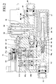
- Figs. 1-3 show an inner structure of a vacuum generator of an embodiment of the present invention.
- Fig. 1 shows a stand-by state in which no vacuum is generated;
- Fig. 1 shows a sucking state in which a large amount of air is sucked from a vacuum port to suck a work piece;
- Fig. 3 shows a holding state in which the work piece is held with consuming a small amount of compressed air.
- Fig. 1 shows the stand-by state in which no vacuum is generated.
- An air-supply port 10 is connected to a source of compressed air, e.g., a compressor.
- the air-supply port 10 is communicated to a supply path 12, which is communicated to a first main valve 60a.
- the supply path 12 is bent and upwardly extended, and it is communicated to a hole 62, which is opened in one side face of a cylinder 61a accommodating the first main valve 60a.
- the first main valve 60a is air-tightly fitted in the cylinder 61a and capable of moving in the axial direction thereof.
- a second main valve 60b which is the same as the first main valve 60a, is accommodated in a cylinder 61b, which is arranged parallel to the cylinder 61a.
- the second main valve 60a too is air-tightly fitted in the cylinder 61b and capable of moving in the axial direction thereof.
- the first main valve 60a and the second main valve 60b are respectively controlled by two pilot valves.
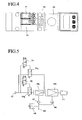
- a plan view of the vacuum generator is shown in Fig. 4.
- the pilot valves 70 and 71 respectively control the motion of the first main valve 60a and the second main valve 60b.
- pilot valve 70 Only the pilot valve 70 is shown in Fig. 1.
- the pilot valve 70 is communicated to a communication path 63, which communicates the cylinder 61a to the cylinder 61b, via a communication path 64.
- a communication path 65a communicates the pilot valve 70 to a bottom part of the cylinder 61a.
- the other pilot valve 71 is communicated to the communication path 63 via the communication path 64 and communicated to a bottom part of the cylinder 61b via a communication path 65b.
- a first communication path 14 is communicated to a hole 66, which is opened in the other side face of the cylinder 61a.
- the first communication path 14 is bent and downwardly extended from the cylinder 61a to a base end of a first nozzle 18a.
- a second nozzle 18b is serially arranged with respect to the first nozzle 18a.
- the vacuum generator of the present embodiment has two nozzles. As clearly shown in the drawing, a diameter of the second nozzle 18b is greater than that of the first nozzle 18a. With this structure, a large amount of compressed air can be jetted from the second nozzle 18b. On the other hand, a small amount of compressed air is jetted from the first nozzle 18a. Namely, the amount of compressed air passing through the first nozzle 18a is limited.
- a second communication path 15 is communicated to a hole 67, which is opened in one side face of the cylinder 61b.
- the second communication path 15 is bent and downwardly extended from the cylinder 61b to a mid part between the first and second nozzles 18a and 18b. With this structure, the compressed air introduced in the second communication path 15 is jetted from the second nozzle 18b.
- a diffuser nozzle 20 is provided on the front side of the second nozzle 18b and arranged coaxial with the first and second nozzles 18a and 18b.
- a silencer element 21 is attached on an inner face of a cylinder 22 so as to encloses a front end part of the diffuser nozzle 20.
- An air-discharge port 40 is opened in a side face of the cylinder 22.
- the air-discharge port 40 includes a plurality of through-holes 40a, which are formed in the side face of the cylinder 22.
- Fig. 1 shows the stand-by state of the vacuum generator. Namely, no air is sucked from the vacuum port 50, so no work piece is sucked thereto.
- valve bodies 70a and 70b close the pilot valves 70 and 71.
- the communication path 64 is isolated from the communication paths 65a and 65b, so that the first and second main valves 60a and 60b are moved downward.
- a down-force which downwardly presses the first and second main valves 60a and 60b and which is generated by pressure of the compressed air flowing through the communication path 63
- an up-force which upwardly presses the first and second main valves 60a and 60b and which is generated by pressure of the compressed air applied to bottom faces, work to the first and second main valves 60a and 60b.
- the first and second main valves 60a and 60b are moved downward and upward by difference of the down-force and the up-force.
- seal rings which are respectively provided to mid parts of the main valves 60a and 60b contact projections respectively provided in inner faces of the cylinders 61a and 61b, so that the seal rings prevents the compressed air from entering the first and second communication paths 14 and 15. With this action, the compressed air, which has been introduced into the air-supply port 10, cannot go forward from the supply path 12. Namely, the vacuum state is not generated.
- Fig. 2 shows the sucking state of the vacuum generator, in which the work piece (not shown) is sucked to the vacuum port 50.
- the vacuum generator sucks the work piece, air is sucked from the vacuum port 50.
- the vacuum port is provided in a side face of the vacuum generator.
- the vacuum port 50 is communicated to a filtering chamber 32 via sucking paths 30 and 31. Air, which has been introduced into the filtering chamber 32 via the sucking paths 30 and 31, passes a filtering element 33, so that the clean air can be gained.
- the clean air is introduced into a base end of the diffuser nozzle 20 via a communication path 34 and a valve chamber 35.
- the valve chamber 35 is communicated to a front end of the second nozzle 18b and the base end of the diffuser nozzle 20.
- air is sucked into the valve chamber 35 and discharged from the air-discharge port 40.
- a check valve 36 which passes air toward the air-discharge port 40 only, is provided in the valve chamber 35.
- a check valve 37 controls communication between the communication path 34 and the second communication path 15.
- the check valve 37 is always biased, by a spring, to shut off the communication between the communication path 34 and the second communication path 15.
- the pilot valve 71 When the vacuum generator sucks the work piece, the pilot valve 71 is actuated to open the valve body 71a.
- the communication path 64 is communicated to the communication path 65b, and the compressed air is introduced into the bottom part of the second main valve 60b, so that the second main valve 60b is moved to the uppermost position.
- the cylinder 61b which has been closed by the second main valve 61b, is opened, so that the cylinder 61b is communicated to the second communication path 15.
- the compressed air which has been introduced from the air-supply port 10 is introduced to the base end of the second nozzle 18b via the supply path 12, the cylinder 61b and the second communication path 15.
- the compressed air in the second communication path 15 presses the check valve 37 to close the communication path 34.
- the compressed air which has been introduced to the base end of the second nozzle 18b, is jetted toward the diffuser nozzle 20, so that vacuum or negative pressure is generated. With this action, air is sucked from the vacuum port 50 and introduced to the valve chamber 35, the communication path 34, the filtering chamber 32, and the sucking paths 30 and 31.
- a diameter of the second nozzle 18b is greater than that of the first nozzle 18a, so a large amount of air is sucked from the vacuum port 50 in the state shown in Fig. 2.
- the work piece can be quickly and securely sucked to the vacuum port 50. In this state, the degree of vacuum in the vacuum port 50 is low.
- Fig. 3 shows the holding state, in which the work piece, which has been sucked to the vacuum port 50, is continuously held by the vacuum port 50. As described above, after the work piece is sucked and once held, the work piece can be held by sucking a small amount of air from the vacuum port 50. In the vacuum generator shown in Fig. 3, the amount of sucking air is limited, and the degree of vacuum in the vacuum port 50 is high.
- a pressure sensor 55 is communicated to the filtering chamber 32.
- the pressure sensor 55 always detects air pressure or the degree of vacuum in the vacuum port 50.
- the valve body 70a of the pilot valve 70 is opened, and the valve body 71a of the pilot valve 71 is closed.
- the pressure sensor 55 detects that the air pressure in the vacuum port 50 is equal to or lower than the prescribed pressure
- the valve body 70a is opened, so that the first main valve 60a is moved from the lowermost position to the uppermost position.
- the valve body 71a is closed, so that the second main valve 60b is moved from the uppermost position to the lowermost position.
- the first main valve 60a is opened, and the second main valve 60b is closed.
- the compressed air which has been supplied to the air-supply port 10
- the second main valve 60b closes the cylinder 61b, so that no compressed air is introduced into the second communication path 15.
- the compressed air which has been supplied to the air-supply port 10 is jetted from the first nozzle 18a toward the diffuser nozzle 20.
- the diameter of the first nozzle 18a is shorter than that of the second nozzle 18b, so that amount of compressed air passing through the first nozzle 18a is smaller than that passing through the second nozzle 18b.
- the compressed air is jetted from the first nozzle 18a toward the diffuser nozzle 20. With this action, vacuum or negative pressure is generated in a space between the first nozzle 18a and the second nozzle 18b and another space between the second nozzle 18b and the diffuser nozzle 20, so that air is sucked to the second communication path 15 and the valve chamber 35.
- the compressed air is introduced to only the first nozzle 18a, which has the small diameter. Therefore, amount of consuming compressed air is small.
- the air pressure in the vacuum port 50 quickly falls down.
- the pressure sensor 55 detects the low pressure in the vacuum port 50, the first and second main valves 60a and 60b are switched from the positions for sucking the work piece to the positions for holding the work piece.
- a large amount of compressed air is consumed in the second nozzle 18b having the great diameter when the vacuum port sucks the work piece.
- a small amount of compressed air is consumed in the first nozzle 18a having the small diameter when the vacuum port continuously holds the work piece, so that the amount of consuming the compressed air can be reduced.
- the vacuum generator of the present embodiment a large amount of compressed air is used when the work piece is sucked, so that the work piece can be quickly and securely sucked. After the work piece is once held, the work piece can be continuously held with consuming a small amount of compressed air. Therefore, the work piece can be securely conveyed, and the compressed air can be efficiently consumed. Especially, in the case of a conveying device in which it takes a long time to convey the work piece, the vacuum generator is capable of much reducing the amount of consuming compressed air.
- the vacuum generator of the present embodiment two nozzles 18a and 18b are provided. Therefore, the work piece is held by sucking function of the both nozzles 18a and 18b. Namely, unlike the vacuum generator in which two nozzles is selectively used to hold the work piece, the vacuum generator of the present embodiment is capable of securely holding the work piece.
- the vacuum generator has one nozzle, amount of consuming compressed air for holding the work piece is equal to that for sucking the work piece, so that the amount of consuming the compressed air cannot be reduced.
- the vacuum generator of the present invention has two nozzles 18a and 18b having different diameters, so that the amount of consuming the compressed air can be reduced.
- the vacuum generator is made wholly flat and compact. Namely, the first and second nozzles 18a and 18b are arranged in series, so that the vacuum generating section of the vacuum generator can be small-sized. Further, paths are designed to efficiently arrange the members, e.g., the first and second main valves 60a and 60b, in a small area, so that the compact vacuum generator can be realized.
- FIG. 5 A circuit diagram of the vacuum generator is shown in Fig. 5.
- the compressed air is supplied to the air-supply port 10 so as to actuate the valve body 71a of the pilot valve 71, so that the compressed air is jetted from the second nozzle 18b, which is capable of jetting a large amount of the compressed air, and air can be sucked to the vacuum port 50.
- the valve body 70a of the pilot valve 70 is actuated, the first and second nozzles 18a and 18b jet the compressed air, and air can be sucked to the vacuum port 50.
Landscapes
- Engineering & Computer Science (AREA)
- Physics & Mathematics (AREA)
- Fluid Mechanics (AREA)
- Mechanical Engineering (AREA)
- General Engineering & Computer Science (AREA)
- Jet Pumps And Other Pumps (AREA)
- Manipulator (AREA)
Applications Claiming Priority (2)
| Application Number | Priority Date | Filing Date | Title |
|---|---|---|---|
| JP2002076447A JP4132897B2 (ja) | 2002-03-19 | 2002-03-19 | 真空発生装置 |
| JP2002076447 | 2002-03-19 |
Publications (2)
| Publication Number | Publication Date |
|---|---|
| EP1348873A1 true EP1348873A1 (fr) | 2003-10-01 |
| EP1348873B1 EP1348873B1 (fr) | 2004-12-22 |
Family
ID=27800372
Family Applications (1)
| Application Number | Title | Priority Date | Filing Date |
|---|---|---|---|
| EP03251610A Expired - Lifetime EP1348873B1 (fr) | 2002-03-19 | 2003-03-17 | Dispositif pour creer le vide |
Country Status (4)
| Country | Link |
|---|---|
| US (1) | US6955526B2 (fr) |
| EP (1) | EP1348873B1 (fr) |
| JP (1) | JP4132897B2 (fr) |
| DE (1) | DE60300225T2 (fr) |
Cited By (6)
| Publication number | Priority date | Publication date | Assignee | Title |
|---|---|---|---|---|
| FR2929663A1 (fr) * | 2008-04-03 | 2009-10-09 | Coval Soc Par Actions Simplifi | Generateur de vide autoregule. |
| EP2125585A1 (fr) * | 2007-03-15 | 2009-12-02 | Korea Pneumatic System Co., Ltd | Système de vide utilisant une cartouche de filtre |
| FR2945086A1 (fr) * | 2009-05-04 | 2010-11-05 | Sapelem | Pompe a air pneumatique et installation d'aspiration et de soufflage correspondante |
| WO2017044627A1 (fr) * | 2015-09-08 | 2017-03-16 | Berkshire Grey Inc. | Systèmes et procédés pour produire une pression de vide dynamique dans un effecteur d'extrémité d'arbre articulé |
| US10300612B2 (en) | 2015-08-26 | 2019-05-28 | Berkshire Grey, Inc. | Systems and methods for providing vacuum valve assemblies for end effectors |
| US10335956B2 (en) | 2016-01-08 | 2019-07-02 | Berkshire Grey, Inc. | Systems and methods for acquiring and moving objects |
Families Citing this family (26)
| Publication number | Priority date | Publication date | Assignee | Title |
|---|---|---|---|---|
| FR2852364B1 (fr) * | 2003-03-11 | 2006-07-21 | Dispositif d'aspiration pneumatique | |
| JP4284687B2 (ja) * | 2005-04-26 | 2009-06-24 | Smc株式会社 | 真空及び真空破壊用複合弁 |
| US20070005030A1 (en) * | 2005-06-21 | 2007-01-04 | Hopkins Mark A | Aspiration control via flow or impedance |
| FR2896833B1 (fr) * | 2006-01-30 | 2008-04-04 | Coval Soc Par Actions Simplifi | Dispositif de commande d'un circuit consommateur de gaz comprime et generateur de vide faisant application |
| US20070248469A1 (en) * | 2006-04-25 | 2007-10-25 | Franklin Electric Co., Inc. | Shallow-Well Pump with Interchangeable Nozzle |
| US8465467B2 (en) | 2006-09-14 | 2013-06-18 | Novartis Ag | Method of controlling an irrigation/aspiration system |
| JP2008150995A (ja) * | 2006-12-15 | 2008-07-03 | Tlv Co Ltd | 蒸気エゼクタ |
| JP2008150996A (ja) * | 2006-12-15 | 2008-07-03 | Tlv Co Ltd | 蒸気エゼクタ |
| JP4582484B2 (ja) | 2006-12-20 | 2010-11-17 | Smc株式会社 | 真空吸着装置 |
| SE530787C2 (sv) * | 2007-01-16 | 2008-09-09 | Xerex Ab | Ejektoranordning med luftningsfunktion |
| GB2509182A (en) | 2012-12-21 | 2014-06-25 | Xerex Ab | Vacuum ejector with multi-nozzle drive stage and booster |
| US10753373B2 (en) | 2012-12-21 | 2020-08-25 | Piab Aktiebolag | Vacuum ejector nozzle with elliptical diverging section |
| GB2509184A (en) | 2012-12-21 | 2014-06-25 | Xerex Ab | Multi-stage vacuum ejector with moulded nozzle having integral valve elements |
| GB2509183A (en) | 2012-12-21 | 2014-06-25 | Xerex Ab | Vacuum ejector with tripped diverging exit flow nozzle |
| US9007589B2 (en) | 2013-09-16 | 2015-04-14 | Honeywell Asca Inc. | Co-located porosity and caliper measurement for membranes and other web products |
| WO2015184205A1 (fr) * | 2014-05-30 | 2015-12-03 | Dayco Ip Holdings, Llc | Système de création de vide ayant un éjecteur, une vanne de commande pneumatique et, facultativement, un aspirateur |
| GB201418117D0 (en) | 2014-10-13 | 2014-11-26 | Xerex Ab | Handling device for foodstuff |
| EP3163093B1 (fr) * | 2015-10-30 | 2020-06-17 | Piab Aktiebolag | Éjecteur à vide élevé |
| JP6767711B2 (ja) | 2017-06-09 | 2020-10-14 | Smc株式会社 | サイレンサおよびサイレンサを用いたエジェクタ |
| CN107725495A (zh) * | 2017-11-16 | 2018-02-23 | 苏州亚米拉机械有限公司 | 真空自动发生控制装置 |
| JP6780821B2 (ja) * | 2018-06-15 | 2020-11-04 | Smc株式会社 | 真空エジェクタ及び封止弁ユニット |
| DE102020202577B4 (de) * | 2020-02-28 | 2022-09-15 | Festo Se & Co. Kg | Ventilmodul, Ventilanordnung und Verfahren |
| CA3189612A1 (fr) | 2020-07-22 | 2022-01-27 | Berkshire Grey Operating Company, Inc. | Systemes et procedes de traitement d'objets utilisant un prehenseur a vide qui realise une retention d'objet par mise sous vide |
| WO2022020159A1 (fr) | 2020-07-22 | 2022-01-27 | Berkshire Grey, Inc. | Systèmes et procédés de traitement d'objets à l'aide d'un dispositif de préhension à dépression à affaissement passif |
| DE102022110635A1 (de) | 2022-05-02 | 2023-11-02 | Festo Se & Co. Kg | Vakuumerzeugervorrichtung |
| CN115163581A (zh) * | 2022-07-08 | 2022-10-11 | 宁波波特气动元件有限公司 | 一种真空发生器 |
Citations (3)
| Publication number | Priority date | Publication date | Assignee | Title |
|---|---|---|---|---|
| US2900978A (en) * | 1953-10-23 | 1959-08-25 | Gasaccumulator Svenska Ab | Suction device |
| EP0346314A2 (fr) * | 1988-06-08 | 1989-12-13 | Peter Tell | Dispositif à éjecteur à vide |
| JPH06264900A (ja) * | 1993-03-11 | 1994-09-20 | Nippon Pisuko:Kk | 真空発生装置 |
Family Cites Families (11)
| Publication number | Priority date | Publication date | Assignee | Title |
|---|---|---|---|---|
| US283229A (en) * | 1883-08-14 | Houseisr | ||
| US1528760A (en) * | 1924-08-11 | 1925-03-10 | Friedmann Louis | Exhaust-steam injector |
| US1858325A (en) * | 1930-05-09 | 1932-05-17 | Firm Alex Friedmann | Arrangement for starting and stopping exhaust steam injectors |
| US2247005A (en) * | 1937-03-19 | 1941-06-24 | Trofimov Ivan | Injector using exhaust steam |
| US2245839A (en) * | 1940-01-08 | 1941-06-17 | Ohio Injector Company | Injector |
| JPS6155399A (ja) | 1984-08-27 | 1986-03-19 | Shoketsu Kinzoku Kogyo Co Ltd | 真空発生装置 |
| US4880358A (en) * | 1988-06-20 | 1989-11-14 | Air-Vac Engineering Company, Inc. | Ultra-high vacuum force, low air consumption pumps |
| WO1993005296A1 (fr) * | 1991-09-10 | 1993-03-18 | Smc Kabushiki Kaisha | Appareil utilisant la pression d'un fluide |
| US5683227A (en) * | 1993-03-31 | 1997-11-04 | Smc Corporation | Multistage ejector assembly |
| SE510780C2 (sv) * | 1996-07-22 | 1999-06-21 | Mecman Ab Rexroth | Anordning för alstring av undertryck samt ramparrangemang med en dylik anordning |
| DE29916531U1 (de) * | 1999-09-20 | 2001-02-08 | Volkmann Thilo | Ejektorpumpe |
-
2002
- 2002-03-19 JP JP2002076447A patent/JP4132897B2/ja not_active Expired - Lifetime
-
2003
- 2003-03-17 EP EP03251610A patent/EP1348873B1/fr not_active Expired - Lifetime
- 2003-03-17 DE DE60300225T patent/DE60300225T2/de not_active Expired - Lifetime
- 2003-03-19 US US10/390,904 patent/US6955526B2/en not_active Expired - Lifetime
Patent Citations (3)
| Publication number | Priority date | Publication date | Assignee | Title |
|---|---|---|---|---|
| US2900978A (en) * | 1953-10-23 | 1959-08-25 | Gasaccumulator Svenska Ab | Suction device |
| EP0346314A2 (fr) * | 1988-06-08 | 1989-12-13 | Peter Tell | Dispositif à éjecteur à vide |
| JPH06264900A (ja) * | 1993-03-11 | 1994-09-20 | Nippon Pisuko:Kk | 真空発生装置 |
Non-Patent Citations (2)
| Title |
|---|
| "SLICK TRICK TO PICK QUICKLY", DESIGN ENGINEERING, MORGAN-GRAMPIAN LTD. LONDON, GB, 1 May 1993 (1993-05-01), pages 7, XP000373204, ISSN: 0308-8448 * |
| PATENT ABSTRACTS OF JAPAN vol. 018, no. 671 (M - 1726) 19 December 1994 (1994-12-19) * |
Cited By (20)
| Publication number | Priority date | Publication date | Assignee | Title |
|---|---|---|---|---|
| EP2125585A1 (fr) * | 2007-03-15 | 2009-12-02 | Korea Pneumatic System Co., Ltd | Système de vide utilisant une cartouche de filtre |
| EP2125585A4 (fr) * | 2007-03-15 | 2012-11-14 | Korea Pneumatic Sys Co Ltd | Système de vide utilisant une cartouche de filtre |
| FR2929663A1 (fr) * | 2008-04-03 | 2009-10-09 | Coval Soc Par Actions Simplifi | Generateur de vide autoregule. |
| FR2945086A1 (fr) * | 2009-05-04 | 2010-11-05 | Sapelem | Pompe a air pneumatique et installation d'aspiration et de soufflage correspondante |
| US10300612B2 (en) | 2015-08-26 | 2019-05-28 | Berkshire Grey, Inc. | Systems and methods for providing vacuum valve assemblies for end effectors |
| US10647005B2 (en) | 2015-08-26 | 2020-05-12 | Berkshire Grey, Inc. | System and methods for providing vacuum valve assemblies for end effectors |
| US10357884B2 (en) | 2015-09-08 | 2019-07-23 | Berkshire Grey, Inc. | Systems and methods for providing dynamic vacuum pressure in an articulated arm end effector |
| WO2017044627A1 (fr) * | 2015-09-08 | 2017-03-16 | Berkshire Grey Inc. | Systèmes et procédés pour produire une pression de vide dynamique dans un effecteur d'extrémité d'arbre articulé |
| US10315315B2 (en) | 2015-09-08 | 2019-06-11 | Berkshire Grey, Inc. | Systems and methods for providing dynamic vacuum pressure in an articulated arm end effector |
| US11945100B2 (en) | 2015-09-08 | 2024-04-02 | Berkshire Grey Operating Company, Inc. | Systems and methods for providing high flow vacuum acquisition in automated systems |
| CN108349093A (zh) * | 2015-09-08 | 2018-07-31 | 伯克希尔格雷股份有限公司 | 用于在活节臂末端执行器中提供动态真空压力的系统和方法 |
| US10399236B2 (en) | 2015-09-08 | 2019-09-03 | Berkshire Grey, Inc. | Systems and methods for providing dynamic vacuum pressure in an articulated arm end effector |
| US10596711B2 (en) | 2015-09-08 | 2020-03-24 | Berkshire Grey, Inc. | Systems and methods for providing dynamic vacuum pressure in an articulated arm end effector |
| US10118300B2 (en) | 2015-09-08 | 2018-11-06 | Berkshire Grey, Inc. | Systems and methods for providing high flow vacuum acquisition in automated systems |
| EP4219094A1 (fr) * | 2015-09-08 | 2023-08-02 | Berkshire Grey Operating Company, Inc. | Systèmes de controle de vide dans un effecteur d'extrémité de bras articulé |
| US10857682B2 (en) | 2015-09-08 | 2020-12-08 | Berkshire Grey, Inc. | Systems and methods for providing high flow vacuum acquisition in automated systems |
| US11198224B2 (en) | 2015-09-08 | 2021-12-14 | Berkshire Grey, Inc. | Systems and methods for providing dynamic vacuum pressure in an articulated arm end effector |
| CN108349093B (zh) * | 2015-09-08 | 2022-01-14 | 伯克希尔格雷股份有限公司 | 用于在活节臂末端执行器中提供动态真空压力的系统和方法 |
| US10850402B2 (en) | 2016-01-08 | 2020-12-01 | Berkshire Grey, Inc. | Systems and methods for acquiring and moving objects |
| US10335956B2 (en) | 2016-01-08 | 2019-07-02 | Berkshire Grey, Inc. | Systems and methods for acquiring and moving objects |
Also Published As
| Publication number | Publication date |
|---|---|
| EP1348873B1 (fr) | 2004-12-22 |
| DE60300225D1 (de) | 2005-01-27 |
| DE60300225T2 (de) | 2005-12-15 |
| US20030180154A1 (en) | 2003-09-25 |
| US6955526B2 (en) | 2005-10-18 |
| JP2003278699A (ja) | 2003-10-02 |
| JP4132897B2 (ja) | 2008-08-13 |
Similar Documents
| Publication | Publication Date | Title |
|---|---|---|
| EP1348873B1 (fr) | Dispositif pour creer le vide | |
| JP3678950B2 (ja) | 真空発生用ユニット | |
| TWI726334B (zh) | 噴射真空泵及密封閥單元 | |
| US7637548B2 (en) | Vacuum suction apparatus having negative pressure actuated vacuum generator switching mechanism | |
| US8662861B2 (en) | Ejector device with ventilation action | |
| JP4678604B2 (ja) | 真空発生ユニット | |
| US9086079B2 (en) | Two-stage air control valve | |
| JP2005163619A (ja) | 真空発生用ユニット | |
| US11448204B2 (en) | Diaphragm pump with valve switching device | |
| US20040105760A1 (en) | Ejector with gas propulsion | |
| US6779985B2 (en) | Vacuum generating device | |
| WO2005005109A1 (fr) | Robinet inverseur | |
| US5996609A (en) | Pilot-operated directional control valve | |
| US11639758B2 (en) | Air-valve unit for vacuum system | |
| JP4495366B2 (ja) | 真空発生器 | |
| JP2002103263A (ja) | 吸着搬送装置 | |
| TW202319323A (zh) | 正負壓切換迴路 | |
| JP3178717B2 (ja) | 真空発生用ユニット | |
| JPH11309686A (ja) | シリンダ付真空発生用ユニット | |
| JPH1122699A (ja) | エゼクタ装置 | |
| JPH04152086A (ja) | 吸着搬送装置 | |
| JPH0861298A (ja) | 負圧発生ユニット | |
| JPH06300000A (ja) | エゼクタ装置 |
Legal Events
| Date | Code | Title | Description |
|---|---|---|---|
| PUAI | Public reference made under article 153(3) epc to a published international application that has entered the european phase |
Free format text: ORIGINAL CODE: 0009012 |
|
| AK | Designated contracting states |
Kind code of ref document: A1 Designated state(s): AT BE BG CH CY CZ DE DK EE ES FI FR GB GR HU IE IT LI LU MC NL PT RO SE SI SK TR |
|
| AX | Request for extension of the european patent |
Extension state: AL LT LV MK |
|
| 17P | Request for examination filed |
Effective date: 20031117 |
|
| GRAP | Despatch of communication of intention to grant a patent |
Free format text: ORIGINAL CODE: EPIDOSNIGR1 |
|
| AKX | Designation fees paid |
Designated state(s): CH DE FR GB IT LI SE |
|
| GRAS | Grant fee paid |
Free format text: ORIGINAL CODE: EPIDOSNIGR3 |
|
| GRAA | (expected) grant |
Free format text: ORIGINAL CODE: 0009210 |
|
| AK | Designated contracting states |
Kind code of ref document: B1 Designated state(s): CH DE FR GB IT LI SE |
|
| REG | Reference to a national code |
Ref country code: GB Ref legal event code: FG4D |
|
| REG | Reference to a national code |
Ref country code: CH Ref legal event code: EP |
|
| REG | Reference to a national code |
Ref country code: IE Ref legal event code: FG4D |
|
| REF | Corresponds to: |
Ref document number: 60300225 Country of ref document: DE Date of ref document: 20050127 Kind code of ref document: P |
|
| REG | Reference to a national code |
Ref country code: CH Ref legal event code: NV Representative=s name: AMMANN PATENTANWAELTE AG BERN |
|
| REG | Reference to a national code |
Ref country code: SE Ref legal event code: TRGR |
|
| PLBE | No opposition filed within time limit |
Free format text: ORIGINAL CODE: 0009261 |
|
| STAA | Information on the status of an ep patent application or granted ep patent |
Free format text: STATUS: NO OPPOSITION FILED WITHIN TIME LIMIT |
|
| 26N | No opposition filed |
Effective date: 20050923 |
|
| ET | Fr: translation filed | ||
| REG | Reference to a national code |
Ref country code: FR Ref legal event code: PLFP Year of fee payment: 13 |
|
| REG | Reference to a national code |
Ref country code: FR Ref legal event code: PLFP Year of fee payment: 14 |
|
| REG | Reference to a national code |
Ref country code: FR Ref legal event code: PLFP Year of fee payment: 15 |
|
| REG | Reference to a national code |
Ref country code: FR Ref legal event code: PLFP Year of fee payment: 16 |
|
| PGFP | Annual fee paid to national office [announced via postgrant information from national office to epo] |
Ref country code: GB Payment date: 20220318 Year of fee payment: 20 Ref country code: DE Payment date: 20220218 Year of fee payment: 20 Ref country code: CH Payment date: 20220223 Year of fee payment: 20 |
|
| PGFP | Annual fee paid to national office [announced via postgrant information from national office to epo] |
Ref country code: SE Payment date: 20220223 Year of fee payment: 20 Ref country code: IT Payment date: 20220224 Year of fee payment: 20 Ref country code: FR Payment date: 20220223 Year of fee payment: 20 |
|
| REG | Reference to a national code |
Ref country code: DE Ref legal event code: R071 Ref document number: 60300225 Country of ref document: DE |
|
| REG | Reference to a national code |
Ref country code: CH Ref legal event code: PL |
|
| REG | Reference to a national code |
Ref country code: GB Ref legal event code: PE20 Expiry date: 20230316 |
|
| REG | Reference to a national code |
Ref country code: SE Ref legal event code: EUG |
|
| PG25 | Lapsed in a contracting state [announced via postgrant information from national office to epo] |
Ref country code: GB Free format text: LAPSE BECAUSE OF EXPIRATION OF PROTECTION Effective date: 20230316 |