EP1348571A1 - Dispositif pour relier des éléments plats empilés - Google Patents
Dispositif pour relier des éléments plats empilés Download PDFInfo
- Publication number
- EP1348571A1 EP1348571A1 EP03005778A EP03005778A EP1348571A1 EP 1348571 A1 EP1348571 A1 EP 1348571A1 EP 03005778 A EP03005778 A EP 03005778A EP 03005778 A EP03005778 A EP 03005778A EP 1348571 A1 EP1348571 A1 EP 1348571A1
- Authority
- EP
- European Patent Office
- Prior art keywords
- connecting means
- perforations
- wire comb
- flat parts
- comb
- Prior art date
- Legal status (The legal status is an assumption and is not a legal conclusion. Google has not performed a legal analysis and makes no representation as to the accuracy of the status listed.)
- Granted
Links
Images


Classifications
-
- B—PERFORMING OPERATIONS; TRANSPORTING
- B42—BOOKBINDING; ALBUMS; FILES; SPECIAL PRINTED MATTER
- B42B—PERMANENTLY ATTACHING TOGETHER SHEETS, QUIRES OR SIGNATURES OR PERMANENTLY ATTACHING OBJECTS THERETO
- B42B5/00—Permanently attaching together sheets, quires or signatures otherwise than by stitching
- B42B5/08—Permanently attaching together sheets, quires or signatures otherwise than by stitching by finger, claw or ring-like elements passing through the sheets, quires or signatures
- B42B5/10—Permanently attaching together sheets, quires or signatures otherwise than by stitching by finger, claw or ring-like elements passing through the sheets, quires or signatures the elements being of castellated or comb-like form
- B42B5/103—Devices for assembling the elements with the stack of sheets
Definitions
- the invention relates to an apparatus and a method for binding flat parts stacked on top of one another, in particular sheets of paper, with the aid an elongated connecting means, which are two curved in cross section Has side sections, which are introduced into edge sections of the Flat parts formed perforations opened and after insertion are closed, in particular a wire comb, with the help of a Introducing the open lanyard into the perforations introduced and with the help of a locking device that into the perforations introduced connection means is closed.
- a device of the type mentioned is usually part of one semi-automatic or fully automatic system for the production of Blocks of paper held together by wire combs.
- Such systems are made from sheets of paper Cutting made, the paper sheets during this step perforated simultaneously in an edge section with the aid of a punching device and possibly printed in a printing unit. Then these Sheets of paper overlap and form blocks with a defined number of Sheets of paper collected.
- the sheets of paper are stacked in such a way that the perforated edge sections are aligned with each other. The latter is important to in the binding device for binding the blocks of paper wire combs with one leg still open at this time insert the perforations of all sheets of paper and push them through can. Then the open wire combs are closed, by the spaced-apart legs towards each other bent to form closed annular segments form.
- the wire combs consist of a large number of adjacent ones Leg or segment pairs, which are connected by connecting sections are connected, and therefore have the shape of a cross to their Longitudinal movable "caterpillar".
- the wire combs are like this prefabricated so that they are delivered with the segments open. in the open state are the segments of each segment pair with their free ends spaced apart, creating each segment pair and thus the wire combs in cross section the shape of a double "C" to have. Because of this special shape, it is important that the wire combs in the binding device as precisely as possible through the perforations of the Sheets of paper can be inserted to enable smooth binding.
- a device for binding stacked Flat parts, in particular sheets of paper using an elongated connecting means, which has two curved side sections in cross section, which are formed before being introduced into edge sections of the flat parts
- Perforations are open and closed after insertion, in particular a wire comb, with an insertion device for inserting the open connection means in the perforations and a device for Closing of the connecting means drawn into the perforations, thereby characterized in that the introduction device has a pivoting means which the open connecting means transverse to its longitudinal extent Subjects pivoting movement and thereby leads along a path that in the Essentially the course of the curvature of the to be drawn in Side section of the connecting means and / or the alignment and Arrangement of the perforations corresponds.
- the object according to a second aspect of the present Invention solved by a method for binding stacked on top of each other Flat parts, especially sheets of paper, with the help of an elongated one Lanyard that has two curved side sections in cross section has, which is formed before introduction into edge portions of the flat parts
- Perforations are open and closed after insertion, especially a wire comb, with the steps that open Insert lanyards into the perforations and then close characterized in that during the step, the open Introducing lanyard into the perforation, the open lanyard subjected to a pivoting movement transversely to its longitudinal extent and is guided along a path that essentially follows the course the curvature of the side section of the connecting means to be introduced and / or the alignment and arrangement of the perforations.
- each in Cross-section have two curved side sections that before insertion are open in the perforations of the flat parts, particularly precisely in the Insert perforations and insert them through them. This will create a ensures smooth binding of the flat parts.
- Pivot means essentially with the fulcrum of the circular or partially circular curvature of the side portion of the connecting means together.
- the introduction device should expediently be an engagement means for Have receptacle of the connecting means.
- a further education of this Execution which a receiving station and a transport device for Transport of the connecting means to the receiving station is distinguished characterized in that the transport device in the connecting means Conveyed longitudinally into the receiving station, where the engaging means Lanyard engages and removes.
- this is Engagement means transverse to the longitudinal extension of the connecting means and / or the pivot axis of the pivot means movable.
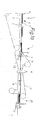
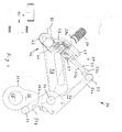
- the conveyor section 1 has a first, straight-line conveyor and Processing section 1 and a second, curved Conveying and processing section 2.
- the conveyor section 1 consists of a loading station 3 with a stop 4 on the stack 6 Paper sheets 7 multiple widths can be created by hand.
- Carriers 9 are provided, from which the stack 6 successively to one Sub-device 11 are eligible.
- the stacks 6 with the aid of pliers 12 divided into partial stacks between two Conveyor belts 13 and 14 are conveyed to a punching device 16.
- the Punching device 16 is arranged transversely to the conveying direction of the stack 6 and acts in this way with a controllable stop 17 between subsequent ones Conveyor belts 18 and 19 together that the partial stack in the area of their rear edge 21 can be provided with a row of holes 22.
- a collecting device 23 in which the part of the stack be accumulated again to a stack 6.
- the stack 6 For removal from the Collecting device 23 serves a controllable pliers 24, the stack 6 as far pulls out of the collecting device 23 that it is then from a cyclically driven conveyor or detected by its drivers 26 become.
- a cutting device 27 follows in the conveying direction arranged knives 28 which the stack 6 multiple widths in blocks 29 divide. The blocks 29 are then processed in FIG subsequent work stations transported, for which in Fig. 1b only the reference numeral 30 is given.
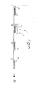
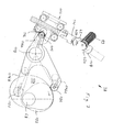
- the following work stations can in particular be a Alignment device, a wire comb retractor and one Wire comb locking device included. While the alignment device in is not shown in the accompanying drawings, is with the Reference numeral 36 marked wire comb retractor in the Figures 2 to 6 and the one designated by reference numeral 38 Wire comb locking device shown in Figures 2 and 7 recognizable.
- the transport device 40 is in the present exemplary embodiment provided with two belt conveyors arranged at right angles to each other whose conveyor belts rest on the wire comb that is still open.
- the Wire comb which is identified by the reference number 42, in Front view shown and thus extends in its longitudinal extent perpendicular to the image plane.
- Fig. 3 the situation is shown in which the wire comb 42 still open Help the transport device 40 straight into the wire comb retractor 36 has been transported.
- the open double C shape is clearly visible of the wire comb 42 with a first approximately semicircular comb segment 42a and a second approximately semicircular comb segment 42b, the free ends of which are spaced from each other.
- the wire comb 42 is in the operating position shown in FIG. 3 already in clamping engagement with a jaw unit 44, the one immovable lower first jaw 46 and a movable upper second Has jaw 48.
- the wire comb 42 lies on the first Clamp 46 on, while the second jaw 48 is engaged the free end of the second leg 42b of the wire comb still open 42 is located.
- the movable second jaw 48 is driven by a pneumatic unit 49 by a control unit, not shown is controlled accordingly, whereby the jaw unit 44 either closed or opened.
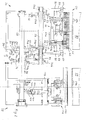
- the jaw unit 44 and the pneumatic unit 49 are part of one Clamping unit 50, which has a body 51 on which a slide 52 is movably mounted.
- the slide 52 has an external one Front element 52a and parallel arranged rods 52b, which through appropriate holes (not shown in the figures) in Body 51 are guided and at their opposite ends Wear the jaw unit 44 with the associated pneumatic unit 49.
- a second roller 64 is mounted, which runs along the circumference of a first cam 66, which on a third shaft 68 is rotatably attached.
- the third shaft 68 is from a driven individual motor, not shown.
- the first cam 66 has a kind of pear shape with a part-circular first section 66a and a radius enlarging, bulging or projecting second section 66b. Rotation of the first cam 66 causes a reciprocal movement of the double lever 54 around the first shaft 56, which leads to an alternating Transport device 40 leading and away from this Movement of the jaw unit 44 leads.
- the jaw unit 44 In the shown in Fig. 3 In the operating position, the jaw unit 44 has the smallest distance from Transport device 40 on with the result that at this point in time wire comb lying in the transport device 40 from the The jaw unit 44 can be gripped in the manner described above can.
- This operating position is achieved in that the roller 64 on second end 54b of the double lever 54 on the second section 66b of the first Cam 66 is present, as can also be seen in FIG. 3. So that the Roller 64 is always in contact with the first cam 66 is a biasing device, not shown in detail provided that biases the double lever 54 accordingly.
- the roller 64 then arrives at the second end 54b of the Double lever 54 on the part-circular first section 66a of the first Cam 66, whereby the distance to the third shaft 68 becomes clear reduced.
- This causes the double lever 54 to pivot, that its first end 54a moves away from the transport device 40 becomes.
- the double lever 54 takes the slide 52 via the hinge 53 corresponding to the clamping unit 50. This in turn means that the The jaw unit 44 is removed from the transport device 40. Since the Wire comb 42 has been received by the jaw unit 44, the transport device 40 is free to the next wire comb in the Transport wire comb retractor 36.
- the first is also Shaft 56 rotatably fixed a second double lever 72 on which a first Support arm 72a and a second support arm 72b are provided.
- the first Support arm 72a carries a first roller 74 which runs along the circumference of a second cam 76 runs, which sits on the third shaft 68 rotatably.
- the second support arm 72b carries a second roller 78 which runs along the circumference a third cam 80, which also runs on the third shaft 68 is rotatably attached.
- the support arm 58 is also not closer by shown biasing device in the direction of the second and third Cam 76 and 80 biased that the rollers 74 and 78 with the second and third cams 76 and 80 always in contact Engagement.
- the body 51 of the clamping unit 50 remains unchanged Relative position to support arm 58.
- each rack 82 arranged thereon Is slidably mounted in the direction of its longitudinal extent (see also Fig. 2).
- Each rack 82 is not located closer to it in the figures designated row of teeth in engagement with a likewise not in the figures Specified ring gear that runs along the circumference of the second Shafts 60 is formed.
- a third double lever 94 can be pivoted with the aid of an articulated shaft 92 stored.
- the third double lever 94 has two parallel arms 94a and 94b on.
- the first arm 94a carries a first roller 96 which runs along the The circumference of a fourth cam 98, which rotates on the third Shaft 68 is attached.
- the second arm 94b facing the support arm 58 carries also wines roll 100, which are along the circumference of a fifth Cam 102 is running; which also rotatably on the third shaft 68 sitting.
- the arrangement is such that the rollers 96, 100 are always in rolling engagement with the fourth and fifth cams 98 and 102 remain.
- the edge portion of the third adjacent the second arm 94b Double arm 94 is provided with a tooth segment 94c, which is also in engagement with one of the two ring gear sections 56 a of the first shaft 56 located.
- the tooth segment 94c is slightly curved and follows one Circular arc, the center of which is with the central axis of the cardan shaft 92 coincides, as shown in FIG. 6.
- the rotation of the fourth and fifth cams 98 and 102 causes one reciprocal pivoting movement of the third double lever 94 around the Cardan shaft 92.
- the toothed segment 94c also becomes a corresponding one reciprocal movement subjected to this movement across the wave 56 transmits to the racks 82.
- the corresponding in reciprocal Gear racks 82 offset in the longitudinal direction transmit this movement again on the second shafts 60, whereby the clamping unit 50 one corresponding pivotal movement is subjected.
- the fourth and fifth cams 98 and 102 are designed so that during the operating positions shown in Figures 3 to 5 Pivotal movement of the clamping unit 50 around the second shafts 60 compared to the support arms 58, but only when the transition 5 into the operating position shown in FIG. 6 takes place. Then the racks 82 are namely in corresponding longitudinal movement offset, whereby the entire clamping unit 50th with respect to the support arms 58 around the second shafts 60 in that in FIG. 6 shown position is pivoted. During this pivotal movement of the Clamping unit 50 falls along the longitudinal axis of the second. Waves 60 with about Center axis of the part-circular comb segment 42a together.
- the wire comb retractor 36 described above is used in illustrated embodiment thus only for hanging the still open wire combs 42, the clamping unit 50, as from the previous description is recognizable, not just for gripping, but is also used to pivot the wire combs 42.
- Wire comb locking device 38 To close the wire combs 42 that are still open, however, there is one Wire comb locking device provided, which in Figures 2 and 7 in is shown individually and is identified by reference numeral 38.
- the wire comb closing device 38 is adjacent to the previous one described wire comb retractor.
- FIG. 2 can be seen in the illustrated embodiment is that in the right Half of FIG. 2 wire comb closing device 38 compared to that in FIG the left half of Fig. 2 wire comb retractor 36 so arranged that the block 29 with the wire comb 42 suspended therein only in the direction of the longitudinal extension of the wire comb 42 from the Wire comb insertion device 36 into the wire comb closing device 38 needs to be transported, making the transport route proportionate can be kept short.
- the positions of the wire comb 42 in the wire comb retractor 36 and in the wire comb closing device 38 with respect to the longitudinal axis with each other.
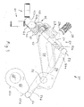
- FIG. 7 Details of the wire comb closing device 38 are exemplified in FIG. 7 shown.
- the view of Fig. 7 has the same perspective as that of Figures 3 to 6; i.e. 7 is the wire comb 42 in front view shown and thus extends at right angles in its longitudinal extent to the image plane.
- the wire comb closing device 38 has one upper first locking bar 108.
- This first locking bar 108 is on a bearing, not shown, which allows the first Locking bar 108 along a relatively short stroke in Direction on and away from the wire comb 42, wherein the Movement is generated by a drive, also not shown.
- the movement stroke of the first locking bar 108 only has to be large enough that when the block 29 is transported into the wire comb closing device 38 and from this a collision with the wire comb 42 is avoided.
- the wire comb closing device 38 also a lower second locking bar 110, which is by a carriage 112 is held.
- This carriage 112 is not shown in detail Slidably mounted, whereby the second locking bar 110 in Direction on the wire comb 42 and is movable away from this.
- the Stroke of the second locking bar 110 is significantly larger than that of the first locking bar 108.
- the wire comb closing device 38 can still be a additional alignment element, which is usually designed as a swivel bar to have the wire comb 42 in a desired position align before engaging with the locking beams 108, 110 in the previously closed is closed.
- a additional Alignment element is not shown in the figures for reasons of clarity shown.
- the block is also by a Transport device, not shown, from the wire comb closing device 38 removed for further processing.
Applications Claiming Priority (2)
| Application Number | Priority Date | Filing Date | Title |
|---|---|---|---|
| DE10214342A DE10214342A1 (de) | 2002-03-28 | 2002-03-28 | Vorrichtung zum Binden von aufeinander gestapelten Flachteilen |
| DE10214342 | 2002-03-28 |
Publications (2)
| Publication Number | Publication Date |
|---|---|
| EP1348571A1 true EP1348571A1 (fr) | 2003-10-01 |
| EP1348571B1 EP1348571B1 (fr) | 2007-08-15 |
Family
ID=27798261
Family Applications (1)
| Application Number | Title | Priority Date | Filing Date |
|---|---|---|---|
| EP03005778A Expired - Lifetime EP1348571B1 (fr) | 2002-03-28 | 2003-03-14 | Dispositif pour relier des éléments plats empilés |
Country Status (5)
| Country | Link |
|---|---|
| US (1) | US6994338B2 (fr) |
| EP (1) | EP1348571B1 (fr) |
| AT (1) | ATE369998T1 (fr) |
| DE (2) | DE10214342A1 (fr) |
| RU (1) | RU2003108532A (fr) |
Cited By (1)
| Publication number | Priority date | Publication date | Assignee | Title |
|---|---|---|---|---|
| DE102009011699A1 (de) | 2008-10-14 | 2010-04-15 | Kugler-Womako Gmbh | Binden von aufeinander gestapelten Flachteilen |
Families Citing this family (3)
| Publication number | Priority date | Publication date | Assignee | Title |
|---|---|---|---|---|
| US7086473B1 (en) * | 2001-09-14 | 2006-08-08 | Wood Group Esp, Inc. | Submersible pumping system with sealing device |
| FR2935802B1 (fr) * | 2008-09-05 | 2012-12-28 | Horiba Abx Sas | Procede et dispositif de classification, de visualisation et d'exploration de donnees biologiques |
| US8267454B2 (en) * | 2009-12-28 | 2012-09-18 | Kawasaki Jukogyo Kabushiki Kaisha | Pick-up style utility vehicle with expandable cargo bed |
Citations (2)
| Publication number | Priority date | Publication date | Assignee | Title |
|---|---|---|---|---|
| DE3141686A1 (de) * | 1980-11-08 | 1982-06-16 | Womako Maschinenkonstruktionen GmbH, 7440 Nürtingen | Verfahren und vorrichtung zum herstellen von bloecken mit drahtkammbindung |
| DE19539213A1 (de) * | 1995-10-21 | 1997-04-24 | Womako Masch Konstr | Vorrichtung zum Überführen von Drahtkammbindungen |
Family Cites Families (9)
| Publication number | Priority date | Publication date | Assignee | Title |
|---|---|---|---|---|
| DE1436067A1 (de) * | 1965-04-08 | 1969-04-17 | Cartiere Paolo Pigna Spa | Verfahren und Vorrichtung zum stetigen und automatischen Spiralheften loser perforierter Blaetter |
| US3451081A (en) * | 1968-01-03 | 1969-06-24 | Burn & Co Ltd James | Book-binding machines |
| GB1461771A (en) * | 1973-01-23 | 1977-01-19 | Redwood Burn Group Ltd | Machines for binding packets of perforated sheets drive mechanism for rotating drums or reels- |
| GB1460444A (en) * | 1973-01-23 | 1977-01-06 | Redwood Burn Group Ltd | Machines for binding packets of perforated sheets |
| GB1541225A (en) * | 1975-02-13 | 1979-02-28 | Burn Bindings Ltd James | Binding of perforated sheets |
| EP0095244A3 (fr) * | 1982-05-21 | 1985-12-18 | James Burn Bindings Limited | Machines à relier au moyen de fil |
| IT1151278B (it) * | 1982-06-04 | 1986-12-17 | Rilecart Spa | Macchina per la foratura e la rilegatura "a spirale" in modo automatico di blocchi di fogli e l'eventuale inserimento dei anci per la preparazione di calendari |
| GB9712718D0 (en) * | 1997-06-18 | 1997-08-20 | Heights Design Production Ltd | Binding apparatus |
| US6409447B2 (en) * | 2000-02-03 | 2002-06-25 | Tanarax, Llc | Bookbinding signature comb and spine device |
-
2002
- 2002-03-28 DE DE10214342A patent/DE10214342A1/de not_active Withdrawn
-
2003
- 2003-03-14 AT AT03005778T patent/ATE369998T1/de not_active IP Right Cessation
- 2003-03-14 EP EP03005778A patent/EP1348571B1/fr not_active Expired - Lifetime
- 2003-03-14 DE DE50307922T patent/DE50307922D1/de not_active Expired - Fee Related
- 2003-03-27 RU RU2003108532/12A patent/RU2003108532A/ru not_active Application Discontinuation
- 2003-03-27 US US10/400,068 patent/US6994338B2/en not_active Expired - Fee Related
Patent Citations (2)
| Publication number | Priority date | Publication date | Assignee | Title |
|---|---|---|---|---|
| DE3141686A1 (de) * | 1980-11-08 | 1982-06-16 | Womako Maschinenkonstruktionen GmbH, 7440 Nürtingen | Verfahren und vorrichtung zum herstellen von bloecken mit drahtkammbindung |
| DE19539213A1 (de) * | 1995-10-21 | 1997-04-24 | Womako Masch Konstr | Vorrichtung zum Überführen von Drahtkammbindungen |
Cited By (2)
| Publication number | Priority date | Publication date | Assignee | Title |
|---|---|---|---|---|
| DE102009011699A1 (de) | 2008-10-14 | 2010-04-15 | Kugler-Womako Gmbh | Binden von aufeinander gestapelten Flachteilen |
| EP2177366A2 (fr) | 2008-10-14 | 2010-04-21 | Kugler-Womako GmbH | Reliure pour éléments plats empilés les uns sur les autres |
Also Published As
| Publication number | Publication date |
|---|---|
| DE50307922D1 (de) | 2007-09-27 |
| RU2003108532A (ru) | 2004-11-10 |
| US20040013496A1 (en) | 2004-01-22 |
| DE10214342A1 (de) | 2003-10-09 |
| EP1348571B1 (fr) | 2007-08-15 |
| US6994338B2 (en) | 2006-02-07 |
| ATE369998T1 (de) | 2007-09-15 |
Similar Documents
| Publication | Publication Date | Title |
|---|---|---|
| EP0711724B1 (fr) | Dispositif pour séparer des sections tubulaires perforées | |
| DE1602617C3 (de) | Vorrichtung zum Abtrennen einer Drahtlänge von einem Drahtbund und Überführen der Drahtlänge zu einer an den Enden der Drahtlänge angreifenden Bearbeitungsstation | |
| EP0341425B1 (fr) | Dispositif pour collationner des produits imprimés pliés | |
| DE2129642B2 (de) | Vorrichtung zum Zuführen von Drahtstücken | |
| EP0399322B1 (fr) | Appareil de brochage | |
| DE4007961A1 (de) | Kontinuierlich arbeitende einhuellmaschine | |
| EP0476718A1 (fr) | Dispositif pour piquer des produits d'imprimerie à plusieurs parties | |
| EP0522319A1 (fr) | Procédé et dispositif pour ouvrir des articles flexible pliés hors du centre | |
| EP1943173B1 (fr) | Procede et dispositif pour transferer des produits plats d'une pile de produits a une bande transporteuse | |
| DE102019001270B3 (de) | Vorrichtung und Verfahren zum Herstellen einer Grillfackel | |
| EP0600216A1 (fr) | Procédé et dispositif pour ouvrir des produits d'imprimerie pliés | |
| CH696035A5 (de) | Vorrichtung zum registergenauen Ausrichten von Produkten aus Bogenmaterial in einer Vorrichtung zur Handhabung von Produkten aus Bogenmaterial. | |
| DE2803775C2 (de) | Vorrichtung zum Binden von Blattlagen mittels einer Spiral-, Kammbindung o.dgl. | |
| EP1348571B1 (fr) | Dispositif pour relier des éléments plats empilés | |
| DE1561141B2 (de) | Vorrichtung zum einfuehren von beilagen in gefaltete druckerzeugnisse | |
| DE3908347C2 (fr) | ||
| EP1411011B1 (fr) | Dispositif pour le transfert de produits à un dispositif de transport | |
| CH627422A5 (de) | Einrichtung fuer die behandlung von schriftstuecken, die zwischen behandlungsstationen befoerdert werden. | |
| EP0301244B1 (fr) | Dispositif pour insérer au moins un supplément dans des imprimés | |
| EP3187439A1 (fr) | Dispositif de transfert de bois | |
| DE10080265B4 (de) | Vorrichtung zum Drehen und Positionieren von auf einer Federwindemaschine hergestellten Federn | |
| EP0896943B1 (fr) | Méthode et dispositif pour la régulation continue d'un matériau imprimable dans un système d'impression | |
| EP0662440A1 (fr) | Dispositif pour l'agrafage par adhésif de produits imprimés | |
| DE2706368B2 (de) | Vorrichtung zum querverlaufenden, zickzackförmigen Falten einer Materialbahn | |
| EP1683752A1 (fr) | Dispositif et méthode pour couper transversalement une bande en articles séparées |
Legal Events
| Date | Code | Title | Description |
|---|---|---|---|
| PUAI | Public reference made under article 153(3) epc to a published international application that has entered the european phase |
Free format text: ORIGINAL CODE: 0009012 |
|
| AK | Designated contracting states |
Kind code of ref document: A1 Designated state(s): AT BE BG CH CY CZ DE DK EE ES FI FR GB GR HU IE IT LI LU MC NL PT RO SE SI SK TR |
|
| AX | Request for extension of the european patent |
Extension state: AL LT LV MK |
|
| 17P | Request for examination filed |
Effective date: 20040401 |
|
| AKX | Designation fees paid |
Designated state(s): AT BE BG CH CY CZ DE DK EE ES FI FR GB GR HU IE IT LI LU MC NL PT RO SE SI SK TR |
|
| GRAP | Despatch of communication of intention to grant a patent |
Free format text: ORIGINAL CODE: EPIDOSNIGR1 |
|
| GRAS | Grant fee paid |
Free format text: ORIGINAL CODE: EPIDOSNIGR3 |
|
| GRAA | (expected) grant |
Free format text: ORIGINAL CODE: 0009210 |
|
| AK | Designated contracting states |
Kind code of ref document: B1 Designated state(s): AT BE BG CH CY CZ DE DK EE ES FI FR GB GR HU IE IT LI LU MC NL PT RO SE SI SK TR |
|
| REG | Reference to a national code |
Ref country code: GB Ref legal event code: FG4D Free format text: NOT ENGLISH |
|
| REG | Reference to a national code |
Ref country code: CH Ref legal event code: EP |
|
| REG | Reference to a national code |
Ref country code: IE Ref legal event code: FG4D Free format text: LANGUAGE OF EP DOCUMENT: GERMAN |
|
| REF | Corresponds to: |
Ref document number: 50307922 Country of ref document: DE Date of ref document: 20070927 Kind code of ref document: P |
|
| PG25 | Lapsed in a contracting state [announced via postgrant information from national office to epo] |
Ref country code: NL Free format text: LAPSE BECAUSE OF FAILURE TO SUBMIT A TRANSLATION OF THE DESCRIPTION OR TO PAY THE FEE WITHIN THE PRESCRIBED TIME-LIMIT Effective date: 20070815 Ref country code: BG Free format text: LAPSE BECAUSE OF FAILURE TO SUBMIT A TRANSLATION OF THE DESCRIPTION OR TO PAY THE FEE WITHIN THE PRESCRIBED TIME-LIMIT Effective date: 20071115 Ref country code: ES Free format text: LAPSE BECAUSE OF FAILURE TO SUBMIT A TRANSLATION OF THE DESCRIPTION OR TO PAY THE FEE WITHIN THE PRESCRIBED TIME-LIMIT Effective date: 20071126 Ref country code: FI Free format text: LAPSE BECAUSE OF FAILURE TO SUBMIT A TRANSLATION OF THE DESCRIPTION OR TO PAY THE FEE WITHIN THE PRESCRIBED TIME-LIMIT Effective date: 20070815 |
|
| NLV1 | Nl: lapsed or annulled due to failure to fulfill the requirements of art. 29p and 29m of the patents act | ||
| GBV | Gb: ep patent (uk) treated as always having been void in accordance with gb section 77(7)/1977 [no translation filed] |
Effective date: 20070815 |
|
| REG | Reference to a national code |
Ref country code: IE Ref legal event code: FD4D |
|
| EN | Fr: translation not filed | ||
| PG25 | Lapsed in a contracting state [announced via postgrant information from national office to epo] |
Ref country code: GR Free format text: LAPSE BECAUSE OF FAILURE TO SUBMIT A TRANSLATION OF THE DESCRIPTION OR TO PAY THE FEE WITHIN THE PRESCRIBED TIME-LIMIT Effective date: 20071116 Ref country code: DK Free format text: LAPSE BECAUSE OF FAILURE TO SUBMIT A TRANSLATION OF THE DESCRIPTION OR TO PAY THE FEE WITHIN THE PRESCRIBED TIME-LIMIT Effective date: 20070815 |
|
| PG25 | Lapsed in a contracting state [announced via postgrant information from national office to epo] |
Ref country code: GB Free format text: LAPSE BECAUSE OF FAILURE TO SUBMIT A TRANSLATION OF THE DESCRIPTION OR TO PAY THE FEE WITHIN THE PRESCRIBED TIME-LIMIT Effective date: 20070815 Ref country code: IE Free format text: LAPSE BECAUSE OF FAILURE TO SUBMIT A TRANSLATION OF THE DESCRIPTION OR TO PAY THE FEE WITHIN THE PRESCRIBED TIME-LIMIT Effective date: 20070815 Ref country code: PT Free format text: LAPSE BECAUSE OF FAILURE TO SUBMIT A TRANSLATION OF THE DESCRIPTION OR TO PAY THE FEE WITHIN THE PRESCRIBED TIME-LIMIT Effective date: 20080115 Ref country code: SK Free format text: LAPSE BECAUSE OF FAILURE TO SUBMIT A TRANSLATION OF THE DESCRIPTION OR TO PAY THE FEE WITHIN THE PRESCRIBED TIME-LIMIT Effective date: 20070815 Ref country code: CZ Free format text: LAPSE BECAUSE OF FAILURE TO SUBMIT A TRANSLATION OF THE DESCRIPTION OR TO PAY THE FEE WITHIN THE PRESCRIBED TIME-LIMIT Effective date: 20070815 |
|
| PLBE | No opposition filed within time limit |
Free format text: ORIGINAL CODE: 0009261 |
|
| STAA | Information on the status of an ep patent application or granted ep patent |
Free format text: STATUS: NO OPPOSITION FILED WITHIN TIME LIMIT |
|
| PG25 | Lapsed in a contracting state [announced via postgrant information from national office to epo] |
Ref country code: RO Free format text: LAPSE BECAUSE OF FAILURE TO SUBMIT A TRANSLATION OF THE DESCRIPTION OR TO PAY THE FEE WITHIN THE PRESCRIBED TIME-LIMIT Effective date: 20070815 Ref country code: SE Free format text: LAPSE BECAUSE OF FAILURE TO SUBMIT A TRANSLATION OF THE DESCRIPTION OR TO PAY THE FEE WITHIN THE PRESCRIBED TIME-LIMIT Effective date: 20071115 |
|
| 26N | No opposition filed |
Effective date: 20080516 |
|
| BERE | Be: lapsed |
Owner name: KUGLER-WOMAKO G.M.B.H. Effective date: 20080331 |
|
| PG25 | Lapsed in a contracting state [announced via postgrant information from national office to epo] |
Ref country code: MC Free format text: LAPSE BECAUSE OF NON-PAYMENT OF DUE FEES Effective date: 20080331 |
|
| REG | Reference to a national code |
Ref country code: CH Ref legal event code: PL |
|
| PG25 | Lapsed in a contracting state [announced via postgrant information from national office to epo] |
Ref country code: EE Free format text: LAPSE BECAUSE OF FAILURE TO SUBMIT A TRANSLATION OF THE DESCRIPTION OR TO PAY THE FEE WITHIN THE PRESCRIBED TIME-LIMIT Effective date: 20070815 Ref country code: LI Free format text: LAPSE BECAUSE OF NON-PAYMENT OF DUE FEES Effective date: 20080331 Ref country code: DE Free format text: LAPSE BECAUSE OF NON-PAYMENT OF DUE FEES Effective date: 20081001 Ref country code: CH Free format text: LAPSE BECAUSE OF NON-PAYMENT OF DUE FEES Effective date: 20080331 |
|
| PG25 | Lapsed in a contracting state [announced via postgrant information from national office to epo] |
Ref country code: BE Free format text: LAPSE BECAUSE OF NON-PAYMENT OF DUE FEES Effective date: 20080331 |
|
| PG25 | Lapsed in a contracting state [announced via postgrant information from national office to epo] |
Ref country code: SI Free format text: LAPSE BECAUSE OF FAILURE TO SUBMIT A TRANSLATION OF THE DESCRIPTION OR TO PAY THE FEE WITHIN THE PRESCRIBED TIME-LIMIT Effective date: 20070815 |
|
| PG25 | Lapsed in a contracting state [announced via postgrant information from national office to epo] |
Ref country code: CY Free format text: LAPSE BECAUSE OF FAILURE TO SUBMIT A TRANSLATION OF THE DESCRIPTION OR TO PAY THE FEE WITHIN THE PRESCRIBED TIME-LIMIT Effective date: 20070815 |
|
| PG25 | Lapsed in a contracting state [announced via postgrant information from national office to epo] |
Ref country code: IT Free format text: LAPSE BECAUSE OF NON-PAYMENT OF DUE FEES Effective date: 20080314 Ref country code: AT Free format text: LAPSE BECAUSE OF NON-PAYMENT OF DUE FEES Effective date: 20080314 |
|
| PG25 | Lapsed in a contracting state [announced via postgrant information from national office to epo] |
Ref country code: HU Free format text: LAPSE BECAUSE OF FAILURE TO SUBMIT A TRANSLATION OF THE DESCRIPTION OR TO PAY THE FEE WITHIN THE PRESCRIBED TIME-LIMIT Effective date: 20080216 Ref country code: LU Free format text: LAPSE BECAUSE OF NON-PAYMENT OF DUE FEES Effective date: 20080314 |
|
| PG25 | Lapsed in a contracting state [announced via postgrant information from national office to epo] |
Ref country code: TR Free format text: LAPSE BECAUSE OF FAILURE TO SUBMIT A TRANSLATION OF THE DESCRIPTION OR TO PAY THE FEE WITHIN THE PRESCRIBED TIME-LIMIT Effective date: 20070815 |
|
| PG25 | Lapsed in a contracting state [announced via postgrant information from national office to epo] |
Ref country code: FR Free format text: LAPSE BECAUSE OF FAILURE TO SUBMIT A TRANSLATION OF THE DESCRIPTION OR TO PAY THE FEE WITHIN THE PRESCRIBED TIME-LIMIT Effective date: 20080411 |