EP1347282B1 - Probeneingabevorrichtung für die eingabe medizinischer proben in einen analysator - Google Patents
Probeneingabevorrichtung für die eingabe medizinischer proben in einen analysator Download PDFInfo
- Publication number
- EP1347282B1 EP1347282B1 EP03450062A EP03450062A EP1347282B1 EP 1347282 B1 EP1347282 B1 EP 1347282B1 EP 03450062 A EP03450062 A EP 03450062A EP 03450062 A EP03450062 A EP 03450062A EP 1347282 B1 EP1347282 B1 EP 1347282B1
- Authority
- EP
- European Patent Office
- Prior art keywords
- intake
- input
- sample
- analyzer
- needle
- Prior art date
- Legal status (The legal status is an assumption and is not a legal conclusion. Google has not performed a legal analysis and makes no representation as to the accuracy of the status listed.)
- Expired - Lifetime
Links
Images

Classifications
-
- G—PHYSICS
- G01—MEASURING; TESTING
- G01N—INVESTIGATING OR ANALYSING MATERIALS BY DETERMINING THEIR CHEMICAL OR PHYSICAL PROPERTIES
- G01N35/00—Automatic analysis not limited to methods or materials provided for in any single one of groups G01N1/00 - G01N33/00; Handling materials therefor
- G01N35/10—Devices for transferring samples or any liquids to, in, or from, the analysis apparatus, e.g. suction devices, injection devices
- G01N35/1095—Devices for transferring samples or any liquids to, in, or from, the analysis apparatus, e.g. suction devices, injection devices for supplying the samples to flow-through analysers
-
- G—PHYSICS
- G01—MEASURING; TESTING
- G01N—INVESTIGATING OR ANALYSING MATERIALS BY DETERMINING THEIR CHEMICAL OR PHYSICAL PROPERTIES
- G01N30/00—Investigating or analysing materials by separation into components using adsorption, absorption or similar phenomena or using ion-exchange, e.g. chromatography or field flow fractionation
- G01N30/02—Column chromatography
- G01N30/04—Preparation or injection of sample to be analysed
- G01N30/16—Injection
- G01N30/18—Injection using a septum or microsyringe
-
- G—PHYSICS
- G01—MEASURING; TESTING
- G01N—INVESTIGATING OR ANALYSING MATERIALS BY DETERMINING THEIR CHEMICAL OR PHYSICAL PROPERTIES
- G01N30/00—Investigating or analysing materials by separation into components using adsorption, absorption or similar phenomena or using ion-exchange, e.g. chromatography or field flow fractionation
- G01N30/02—Column chromatography
- G01N30/04—Preparation or injection of sample to be analysed
- G01N30/16—Injection
- G01N30/18—Injection using a septum or microsyringe
- G01N2030/185—Injection using a septum or microsyringe specially adapted to seal the inlet
-
- G—PHYSICS
- G01—MEASURING; TESTING
- G01N—INVESTIGATING OR ANALYSING MATERIALS BY DETERMINING THEIR CHEMICAL OR PHYSICAL PROPERTIES
- G01N35/00—Automatic analysis not limited to methods or materials provided for in any single one of groups G01N1/00 - G01N33/00; Handling materials therefor
- G01N2035/00178—Special arrangements of analysers
- G01N2035/00237—Handling microquantities of analyte, e.g. microvalves, capillary networks
Definitions
- the invention relates to a sample input device for the input of medical samples, preferably blood samples from different sampling vessels in an analyzer, wherein the sample transport between the sample input and the measuring cells of the analyzer via gas-tight sample lines.
- Such input devices are known for example from the medical laboratory operation, where they are used for example for blood analysis or other measurements of body fluids.
- analyzers are specialized only in one type of sample input, so that, for example, their input device allow the input of the sample only with the aid of a capillary or a syringe.
- EP 0 297 082 discloses an analyzer for the examination of body fluid samples, which has a rotatable docking note which can be connected in different rotational positions to a filler neck of the sample supply line of the analyzer.
- the sample can also be fed via this docking disk, whereby it can either be sucked in by means of a peristaltic pump or injected into the sample feed.
- the advantage of such a sample input system is that, starting from the input element of the analyzer, all supplied sample, calibration and cleaning media cover the same sample path within the analyzer and thus the same measurement conditions prevail for all media, in contrast to known devices which are suitable for different sampling vessels have different input points.
- a similar sample input device as in EP 0 297 082 is described in DE 38 90 175 C1.
- a rotatably mounted around an axis distributor disc is provided which has a plurality of spaced at the same distance from the axis of rotation input elements, via corresponding connections are connected to the supplied media.
- the distributor disc is mounted via a carrier shaft in the housing of the analyzer, which further includes a control unit for the rotational and lifting movement of the distributor disc. In a rotational position, the distributor disc has a recess, so that in this position, the sample input port for entering the sample by means of pipette or syringe is exposed.
- the sample can thus be sucked from a capillary or injected by means of a syringe, wherein for sealingly receiving the capillary or the syringe, a conical inlet opening is provided, which via a rigid, gas-tight Line is connected directly to the measuring cells of the analyzer.
- the input device is not suitable for a third laboratory preferred input mode, namely the input by sucking from a syringe.
- a negative pressure would arise in the interior of the syringe and the line system of the analyzer when sucking the sample from a syringe so that upon removal of the syringe by the sudden pressure equalization fragmentation of the sample including air bubbles would be created and the measurement difficult or Measured values would be corrupted.
- sample input devices are also known with which the sample can be drawn in from a syringe. These include a plurality of different input devices, in which a pivotable input needle is provided, so that in different positions of the needle from different sampling vessels, the sample liquid can be sucked into the analyzer.
- a pivotable input needle is provided, so that in different positions of the needle from different sampling vessels, the sample liquid can be sucked into the analyzer.
- US Pat. No. 4,499,053 A shows a mechanically relatively complicated lifting mechanism with slide guide, it being possible to suck in a sample from both a capillary and from a syringe.
- the input needle has an input element, which can be guided axially with its central opening by means of a link control on the input needle.
- the input needle from a rest position in which the needle with a connection for a washing solution is connected are pivoted into several different positions, wherein - due to the link control - the input element occupies different positions along the axis of the input needle.
- the needle tip In one of the stroke positions, the needle tip is completely free, so that it can be immersed in open sample vessels and the sample is then drawn in. In a further stroke position, the needle tip is located within the central opening of the input element, so that a sample capillary can be inserted into the remaining region of the central opening and held there. The sample can then be drawn in through the pump of the analyzer.
- a further stroke position is provided in which the input needle assumes a substantially horizontal position and wherein the input element releases a small piece of the needle tip.
- the cone of a syringe can now be passed over the needle tip and pressed against the outer surface of the input element, after which the sample is injected into the analyzer.
- a disadvantage is that the plunger syringe is not held by the input device, that only an insufficient sealing function is given by the outer surface of the input element and there is a risk that parts of the sample contaminate the input device.
- US Pat. No. 5,391,499 A describes an input system in which sample input with two different sampling vessels, namely with a syringe (see FIG. 1) or a sample capillary (see FIG. 2), is possible.
- a rotatable element in the region of the sample input can be determined automatically based on the diameter of the sampling vessel whether a syringe or a Probenkapillare was introduced into the input port and so a different input for the two types of input program can be started.
- the input needle is moved by means of a drive unit either in the longitudinal direction forward to penetrate into the syringe or withdrawn to a capillary To make room. Because of the longitudinally displaceable input needle of US Pat. No.
- the object of the present invention is to develop a sample input device for the input of medical samples, preferably blood samples, in such a way that it is possible to sample from different sampling vessels in the mechanically most possible simple manner, wherein the sample transport between the sample input and the measuring cells of the analyzer continues to be preferably rigid , gas-tight lines should be made.
- a sample inlet side arranged on the analyzer, fixed input needle which has an axially displaceable on the input needle, elastic input element with a conical input opening, and that further a displaceable with respect to the input element and axially parallel to the input needle displaceable holding element is provided, which releases the input element in a first position and positioned in a second position above the input element a conical opening for receiving a syringe.
- the sample in the first position of the holding element in which the conical input opening of the elastic input element is released, the sample can either be sucked out of a capillary or injected by means of a syringe.
- the holding element serves to receive the syringe, which is positioned above the input needle and pushed by a subsequent stroke movement of the holding element on the input needle. Subsequently, the sample can be sucked from the interior of the syringe, wherein to avoid a negative pressure ambient air can flow through the annular gap between the input needle and syringe cone.
- the holding element may be rotatably mounted about a rotationally aligned at a distance r to the input needle, so that in a first rotational position, the input element is exposed and in a second rotational position on the input element, the conical opening for receiving the Piston syringe is positioned.
- the holding element may be designed as a flap and rotatably mounted about a rotational axis lying in a normal plane of the input needle, so that in a first folding position, the input element is exposed and in a second folded position on the input element, the conical opening for receiving the syringe is positioned.
- the analyzer has a drive unit controlled by a processor unit of the analyzer for the lifting and rotary movement or lifting and folding movement of the holding element.
- a development of the invention provides that the analyzer for the axial displacement of the elastic input element from a first position in the region of the tip of the input needle to a second position in which the needle tip protrudes beyond the input element, has a driven by a processor unit of the analyzer drive unit , which is connected via an actuating element with the elastic input element.
- the holding element is designed as a distributor disc for the supply of calibration, quality control and / or washing media, wherein at intervals r in other rotational positions of the distributor disc respectively connections for calibration, quality control and / or washing media are provided which can be brought into contact with the input element.
- the input needle 4 has a coupling element 7 on the device side, so that it can be replaced if necessary.
- an axially displaceable, elastic input element 8 is arranged with a conical input opening 9, wherein the conical opening 9 both for sealingly receiving a sample capillary 10 (see FIG. 1) and the connecting cone of a syringe 11 (see FIG. 2) suitable is.
- the axial displacement of the elastic input element 8 takes place between a first position (see FIGS. 1 to 3), in which the input element 8 is present in the region of the tip 15 of the input needle 4 and a position in the middle region of the input needle 4 (see FIG. 4). in which the tip 15 of the needle protrudes beyond the input element 8.
- the input device has an axially displaceable holding element 16 rotatably mounted about the axis 16 'at a distance r from the input needle 4, which in a first rotational position (FIGS. 1, 2 and 5) releases the input element 8 for certain types of sample input and in a second, by the angle ⁇ rotated position (Fig. 3 and 4) above the elastic input member 8 arranged in the holding element 16, conical opening 17 for receiving a syringe 11 so positioned that the axis 4 'of the rigid input needle 4 with the Axis 17 ', the conical opening 17 coincides.
- a further drive unit 18 controlled by the processor unit 14 is provided in the analyzer 3.
- the retaining element 16 may be formed as a distributor disk for the supply of calibration, quality control and / or washing media, for which at a distance r from the rotation axis 16 'terminals 22 in other positions on the underside of Distributor disc 16 are arranged.
- each of these connections 22 can be inserted into the elastic input element 8 and thus the corresponding calibration, quality control and / or washing medium can be sucked into the input needle 4.
- the holding element 16 is designed as a flap mounted on one side.
- the rotation axis 16 "lies at a distance r in a normal plane ⁇ of the input needle 4 and supports the flap on a support element 23 which performs the necessary lifting movement in order to pull the syringe 11 over the rigid input needle 4.
- a first folded position of the holding element 16 (FIG. dashed line) is the input element 8 for the sample input, for example, from a capillary free, in a second folded position for receiving the plunger syringe 11, the conical opening 17 of the flap over the input element 8 is folded.
- the holding element 16 can also be translated from a first position (input element 8 free) to a second position (conical opening 17 above the input element 8) and then a lifting movement be performed with the aid of the support member 23.
Landscapes
- General Health & Medical Sciences (AREA)
- Physics & Mathematics (AREA)
- Life Sciences & Earth Sciences (AREA)
- Chemical & Material Sciences (AREA)
- Analytical Chemistry (AREA)
- Biochemistry (AREA)
- Immunology (AREA)
- General Physics & Mathematics (AREA)
- Health & Medical Sciences (AREA)
- Pathology (AREA)
- Sampling And Sample Adjustment (AREA)
- Automatic Analysis And Handling Materials Therefor (AREA)
- Measurement Of The Respiration, Hearing Ability, Form, And Blood Characteristics Of Living Organisms (AREA)
- Investigating Or Analysing Biological Materials (AREA)
Description
- Die Erfindung betrifft eine Probeneingabevorrichtung für die Eingabe medizinischer Proben, vorzugsweise Blutproben, aus unterschiedlichen Probennahmegefäßen in einen Analysator, wobei der Probentransport zwischen der Probeneingabe und den Messzellen des Analysators über gasdichte Probenleitungen erfolgt.
- Derartige Eingabevorrichtungen sind beispielsweise aus dem medizinischen Laborbetrieb bekannt, wo sie beispielsweise zur Blutanalyse oder sonstigen Messungen von Körperflüssigkeiten verwendet werden. Vielfach sind Analysatoren lediglich auf eine Art der Probeneingabe spezialisiert, so dass beispielsweise deren Eingabevorrichtung die Eingabe der Probe nur mit Hilfe einer Kapillare oder einer Spritze erlauben.
- Es bestand daher schon früher der Wunsch Probeneingabeeinrichtungen zu entwickeln, welche sich sowohl für die Probeneingabe mittels Kolbenspritze als auch Kapillare eigne, ohne umständliche Adaptierungsarbeiten vornehmen zu müssen.
- So ist beispielsweise aus der EP 0 297 082 ein Analysengerät zur Untersuchung von Körperflüssigkeitsproben bekannt geworden, welcher eine drehbare Andockschreibe aufweist, die in unterschiedlichen Drehstellungen mit einem Einfüllstutzen der Probenzuführleitung des Analysators in Verbindung gebracht werden kann. Über diese Andockscheibe kann auch die Probe zugeführt werden, wobei diese entweder mittels einer Schlauchpumpe eingesogen oder in die Probenzuführung eingespritzt werden kann. Der Vorteil eines derartigen Probeneingabesystems besteht darin, dass ab dem Eingabeelement des Analysators sämtliche zugeführten Probe-, Kalibrier- und Reinigungsmedien innerhalb des Analysators den selben Probenweg zurücklegen und somit für alle Medien die selben Messbedingungen herrschen, im Gegensatz zu bekannten Vorrichtungen, welche für verschiedene Probennahmegefäße unterschiedliche Eingabestellen aufweisen.
- Eine ähnliche Probeneingabevorrichtung wie in der EP 0 297 082 wird in der DE 38 90 175 C1 beschrieben. Bei dieser Eingabevorrichtung ist eine um eine Achse drehbar gelagerte Verteilerscheibe vorgesehen, welche mehrere im gleichen Abstand zur Drehachse angeordnete Eingabeelemente aufweist, die über entsprechende Anschlüsse mit den zuzuführenden Medien verbunden sind. Die Verteilerscheibe ist über eine Trägerwelle im Gehäuse des Analysators gelagert, welcher weiters eine Steuereinheit für die Dreh- und Hubbewegung der Verteilerscheibe beinhaltet. In einer Drehposition weist die Verteilerscheibe eine Aussparung auf, so dass in dieser Position die Probeneingabeöffnung zur Eingabe der Probe mittels Pipette oder Spritze frei liegt. Mit Hilfe der in der DE 38 90 175 C1 beschriebenen Eingabevorrichtung kann somit die Probe aus einer Kapillare eingesogen oder mit Hilfe einer Kolbenspritze eingespritzt werden, wobei zur dichtenden Aufnahme der Kapillare bzw. der Kolbenspritze eine konische Eingabeöffnung vorgesehen ist, welche über eine starre, gasdichte Leitung direkt mit den Messzellen des Analysators verbunden ist. Die Eingabevorrichtung eignet sich allerdings nicht für eine dritte in Labors bevorzugte Eingabeart, nämlich der Eingabe durch Einsaugen aus einer Kolbenspritze. Bei der beschriebenen Vorrichtung würde beim Einsaugen der Probe aus einer Kolbenspritze ein Unterdruck im Inneren der Kolbenspritze sowie im Leitungssystem des Analysators entstehen, sodass beim Entfernen der Kolbenspritze durch den plötzlichen Druckausgleich eine Fragmentierung der Probe unter Einschluss von Luftbläschen entstünde und die Messung erschwert bzw. die Messwerte verfälscht würden.
- Ähnliche Probleme beim Einsaugen der Probe aus einer Kolbenspritze wären auch bei einer aus der EP 0 564 439 A2 bekannten Eingabevorrichtung zu erwarten. Für die Zufuhr von Wasch- und Referenzmedien ist hier eine um eine feststehende Achse verschwenkbare Klappe vorgesehen, über welche bei geschlossener Klappe die Wasch- und Referenzmedien einem elastischen Eingabeelement des Analysators zugeführt werden. Bei geöffneter Klappe ist das Eingabeelement für das Einsaugen aus Kapillaren bzw. das Einspritzen mittels einer Kolbenspritze frei zugängig.
- Es sind allerdings auch Probeneingabevorrichtungen bekannt, mit welchen die Probe aus einer Kolbenspritze eingesogen werden kann. Dazu zählen eine Vielzahl von unterschiedlichen Eingabevorrichtungen, bei welchen eine verschwenkbare Eingabenadel vorgesehen ist, so dass in unterschiedlichen Stellungen der Nadel aus unterschiedlichen Probennahmegefäßen die Probenflüssigkeit in den Analysator gesogen werden kann. In diesem Zusammenhang sei auf die US 4,499,053 A verwiesen, welche einen mechanisch relativ komplizierten Hubmechanismus mit Kulissenführung zeigt, wobei das Einsaugen einer Probe sowohl aus einer Kapillare als auch aus einer Kolbenspritze möglich ist. Dazu weist die Eingabenadel ein Eingabeelement auf, welches mit dessen zentraler Öffnung mit Hilfe einer Kulissensteuerung auf der Eingabenadel axial geführt werden kann. Durch einen Handgriff der Kulissensteuerung kann die Eingabenadel aus einer Ruheposition, in welcher die Nadel mit einem Anschluss für eine Waschlösung verbunden ist, in mehrere unterschiedliche Positionen hochgeschwenkt werden, wobei - bedingt durch die Kulissensteuerung - das Eingabeelement unterschiedliche Positionen entlang der Achse der Eingabenadel einnimmt.
- In einer der Hubpositionen ist die Nadelspitze völlig frei, so dass diese in offene Probengefäße eingetaucht werden kann und die Probe anschließend eingesogen wird. In einer weiteren Hubposition befindet sich die Nadelspitze innerhalb der zentralen Öffnung des Eingabeelementes, so dass in den freibleibenden Bereich der zentralen Öffnung eine Probenkapillare eingeschoben und dort gehalten werden kann. Die Probe kann anschließend durch die Pumpe des Analysators eingesogen werden.
- Schließlich ist eine weitere Hubposition vorgesehen, in welcher die Eingabenadel eine im Wesentlichen waagrechte Stellung einnimmt und wobei das Eingabeelement ein kleines Stück der Nadelspitze freigibt. Der Konus einer Kolbenspritze kann nun über die Nadelspitze geführt und gegen die äußere Fläche des Eingabeelementes gepresst werden, wonach die Probe in den Analysator eingespritzt wird. Als Nachteil ist zu erwähnen, dass die Kolbenspritze von der Eingabevorrichtung nicht gehalten wird, dass durch die äußere Fläche des Eingabeelementes nur eine unzureichende Dichtfunktion gegeben ist und Gefahr besteht, dass Teile der Probe die Eingabeeinrichtung verunreinigen.
- Ein großer Nachteil der Eingabevorrichtung gemäß US 4,499,053 A besteht allerdings darin, dass die verschwenkbare Nadel geräteseitig über einen flexiblen Schlauch mit den Messzellen in Verbindung steht und bewegliche Teile sowie flexible, gasdurchlässige Schläuche im Bereich zwischen Probeneingabe und Messzellen vermieden werden sollen.
- Ähnliche Probleme mit flexiblen Leitungssystemen treten auch bei bekannten Vorrichtungen auf, bei welchen die Eingabenadel mit Hilfe einer Antriebsvorrichtung in das Innere einer Kolbenspritze geführt wird.
- In diesem Zusammenhang wird in der US 5,391,499 A ein Eingabesystem beschrieben, bei welchem die Probeneingabe mit zwei unterschiedlichen Probennahmegefäßen, nämlich mit einer Kolbenspritze (siehe Fig. 1) oder einer Probenkapillare (siehe Fig. 2) möglich ist. Mit Hilfe eines drehbaren Elementes im Bereich der Probeneingabe kann anhand des Durchmessers des Probennahmegefäßes automatisch festgestellt werden, ob eine Kolbenspritze oder eine Probenkapillare in die Eingabeöffnung eingeführt wurde und so ein für die beiden Eingabearten unterschiedliches Eingabeprogramm gestartet werden. Dabei wird die Eingabenadel mit Hilfe einer Antriebeinheit entweder in Längsrichtung nach vorne bewegt, um in die Kolbenspritze einzudringen oder zurückgezogen, um einer Kapillare Platz zu machen. Aufgrund der in Längsrichtung verschiebbaren Eingabenadel der US 5,391,499 A ist auch ein flexibler (und damit gasdurchlässiger) Schlauch für den Anschluss an die Messzelle notwendig, was gemäß obigen Ausführungen nachteilig ist und vermieden werden soll. Ein weiterer Nachteil des Eingabesystems gemäß US 5,391,499 A besteht darin, dass damit das Einspritzen der Probe aus einer Kolbenspritze nicht möglich, da die Probe bei seitlichen Öffnungen zur Zu- und Abfuhr der Waschlösung austreten würde.
- Weiters ist es bekannt, für unterschiedliche Probennahmegefäße unterschiedliche Adapter zu verwenden, welche auf das eigentliche Eingabeelement des Analysators autgesetzt oder in dieses eingeführt werden müssen. Dadurch wird allerdings der Manipulationsaufwand beträchtlich erhöht und das Risiko einer Fehlbedienung vergrößert.
- Aufgabe der vorliegenden Erfindung ist es, eine Probeneingabevorrichtung für die Eingabe medizinischer Proben, vorzugsweise Blutproben, derart weiterzubilden, dass auf mechanisch möglichste einfache Weise die Probennahme aus unterschiedlichen Probennahmegefäßen möglich ist, wobei der Probentransport zwischen der Probeneingabe und den Messzellen des Analysators weiterhin über vorzugsweise starre, gasdichte Leitungen erfolgen soll.
- Diese Aufgabe wird erfindungsgemäß dadurch gelöst, dass eine am Analysator probeneingangsseitig angeordnete, feststehende Eingabenadel vorgesehen ist, welche ein axial auf der Eingabenadel verschiebbares, elastisches Eingabeelement mit einer konischen Eingabeöffnung aufweist, sowie dass weiters ein in Bezug auf das Eingabeelement verlagerbares und parallel zur Eingabenadel axial verschiebbares Haltelement vorgesehen ist, welches in einer ersten Stellung das Eingabeelement frei gibt und in einer zweiten Stellung über dem Eingabeelement eine konische Öffnung zur Aufnahme einer Kolbenspritze positioniert. Vorteilhafterweise kann in der ersten Stellung des Halteelementes, in welcher die konische Eingabeöffnung des elastischen Eingabeelementes freigegeben wird, die Probe entweder aus einer Kapillare eingesogen oder mit Hilfe einer Kolbenspritze eingespritzt werden. In der zweiten Stellung, welche ausgehend von der ersten Stellung durch eine translatorische oder rotatorische Verlagerung des Halteelementes erreicht wird, dient das Halteelement zur Aufnahme der Kolbenspritze, wobei diese über der Eingabenadel positioniert und durch eine anschließende Hubbewegung des Halteelementes über die Eingabenadel geschoben wird. Anschließend kann die Probe aus dem Inneren der Kolbenspritze gesogen werden, wobei zur Vermeidung eines Unterdrucks Umgebungsluft durch den ringförmigen Spalt zwischen Eingabenadel und Spritzenkonus nachströmen kann.
- Gemäß einer ersten Ausführungsvariante der Erfindung kann das Halteelement um eine im Abstand r zur Eingabenadel, parallel zu dieser ausgerichteten Drehachse drehbar gelagert sein, so dass in einer ersten Drehstellung das Eingabeelement frei liegt und in einer zweiten Drehstellung über dem Eingabeelement die konische Öffnung zur Aufnahme der Kolbenspritze positioniert wird.
- Gemäß einer zweiten Ausführungsvariante kann das Halteelement als Klappe ausgebildet sein und um eine in einer Normalebene der Eingabenadel liegende Drehachse drehbar gelagert sein, so dass in einer ersten Klappstellung das Eingabeelement frei liegt und in einer zweiten Klappstellung über dem Eingabeelement die konische Öffnung zur Aufnahme der Kolbenspritze positioniert wird.
- Erfindungsgemäß ist vorgesehen, dass der Analysator für die Hub- und Drehbewegung bzw. Hub- und Klappbewegung des Halteelementes eine von einer Prozessoreinheit des Analysators angesteuerte Antriebseinheit aufweist.
- Eine Weiterbildung der Erfindung sieht vor, dass der Analysator für die axiale Verschiebung des elastischen Eingabeelementes von einer ersten Position im Bereich der Spitze der Eingabenadel in eine zweite Position, in welcher die Nadelspitze über das Eingabeelement hinausragt, eine von einer Prozessoreinheit des Analysators angesteuerte Antriebseinheit aufweist, welche über ein Betätigungselement mit dem elastischen Eingabeelement verbunden ist.
- Eine besonders vorteilhafte Ausführungsvariante der Erfindung ist dadurch gegeben, dass das Halteelement als Verteilerscheibe für die Zufuhr von Kalibrier-, Qualitätskontroll- und/oder Waschmedien ausgebildet ist, wobei im Abstand r in weiteren Drehstellungen der Verteilerscheibe jeweils Anschlüsse für Kalibrier-, Qualitätskontroll- und/oder Waschmedien vorgesehen sind, welche mit dem Eingabeelement in Kontakt bringbar sind.
- Die Erfindung wird im Folgenden anhand von Zeichnungen näher erläutert. Es zeigen die
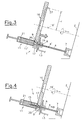
- Fig. 1 bis 4
- in zum Teil schematischer Darstellung eine erste Variante der erfindungsgemäßen Probeneingabevorrichtung für die Eingabe medizinischer Proben in einen Analysator in unterschiedlichen Betriebzuständen jeweils in einer Schnittdarstellung,
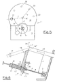
- Fig. 5
- eine Draufsicht auf die Probeneingabevorrichtung nach Fig. 1 bis 4, sowie
- Fig. 6
- eine weitere Ausführungsvariante der Erfindung in einer Schnittdarstellung gemäß Fig. 3.
- Die in den Fig. 1 bis 5 dargestellte Ausführungsvariante einer Probeneingabevorrichtung 1 für eine durch dessen Frontplatte 2 angedeuteten Analysator 3, weist eine starre Eingabenadel 4, beispielsweise eine Stahlnadel auf, welche über eine starre, gasdichte Probenleitung 5 mit den Messzellen 6 im Analysator 3 in Verbindung steht. Die Eingabenadel 4 weist geräteseitig ein Kupplungselement 7 auf, so dass diese bei Bedarf ausgewechselt werden kann.
- Auf der Eingabenadel 4 ist ein axial verschiebbares, elastisches Eingabeelement 8 mit einer konischen Eingabeöffnung 9 angeordnet, wobei die konische Öffnung 9 sowohl zur dichtenden Aufnahme einer Probenkapillare 10 (siehe Fig. 1) als auch des Anschlusskonus einer Kolbenspritze 11 (siehe Fig. 2) geeignet ist. Die axiale Verschiebung des Eingabeelementes 8 erfolgt über ein Betätigungselement 13 mit Hilfe einer im Analysator 3 angeordneten Antriebseinheit 12, welche von einer Prozessoreinheit 14 angesteuert wird. Die axiale Verschiebung des elastischen Eingabeelementes 8 erfolgt zwischen einer ersten Position (siehe Fig. 1 bis 3), in welcher das Eingabeelement 8 im Bereich der Spitze 15 der Eingabenadel 4 vorliegt und einer Position im mittleren Bereich der Eingabenadel 4 (siehe Fig. 4), in welcher die Spitze 15 der Nadel über das Eingabeelement 8 hinausragt.
- Weiters weist die Eingabevorrichtung ein um die Achse 16' im Abstand r zur Eingabenadel 4 drehbar gelagertes, axial verschiebbares Halteelement 16 auf, welches in einer ersten Drehstellung (Fig. 1, 2 und 5), das Eingabeelement 8 für bestimmte Arten der Probeneingabe freigibt und in einer zweiten, um den Winkel β gedrehten Stellung (Fig. 3 und 4) über dem elastischen Eingabeelement 8 eine im Halteelement 16 angeordnete, konische Öffnung 17 zur Aufnahme einer Kolbenspritze 11 derart positioniert, dass die Achse 4' der starren Eingabenadel 4 mit der Achse 17' der konische Öffnung 17 zusammenfällt. Für die Hub- und Drehbewegung des Halteelementes 16 ist im Analysator 3 eine von der Prozessoreinheit 14 angesteuerte weitere Antriebseinheit 18 vorgesehen.
- Die erfindungsgemäße Probeneingabevorrichtung eignet sich somit bestens für die drei bevorzugten Arten der Probeneingabe:
- Einsaugen der Probe aus Probenröhrchen mit kleinem Durchmesser, beispielsweise aus einer Probenkapillare: Die Eingabevorrichtung befindet sich dazu in dem in Fig. 1 dargestellten Betriebszustand, das heißt, das elastische Eingabeelement 8 befindet sich im Bereich der Spitze 15 der starren Eingabenadel 4 und das Halteelement 16 in seiner ersten Drehstellung, in welcher das Eingabeelement 8 für die Probeneingabe mittels Probenkapillare 10 freigegeben wird. Die Probenkapillare 10 wird nun in die konische Eingabeöffnung 9 des elastischen Eingabeelementes 8 eingeführt, bis diese in der Führungsöffnung für die Eingabenadel 4 dichtend gehalten wird. Danach wird eine nicht weiter dargestellte Pumpvorrichtung des Analysators 3 aktiviert und die Probe aus der Probenkapillare in den Analysator eingesogen. Der Einsaugvorgang kann manuell über ein Display des Analysators gestartet werden oder auch automatisch beispielsweise über weiter nicht dargestellte optische Erkennungsmittel im Bereich der Eingabeöffnung 9, welche unterschiedliche Probennahmegefäße am unterschiedlichen Durchmesser unterscheiden können.
- Einspritzen der Probe aus einer Kolbenspritze: Diese Art der Probeneingabe ist in Fig. 2 schematisch dargestellt. Die Probeneingabevorrichtung 1 befindet sich dazu in der selben Ausgangsstellung wie in Fig. 1, wobei in diesem Fall der Anschlusskonus 20 der Kolbenspritze 11 in die konische Eingabeöffnung 9 des elastischen Eingabeelementes 8 dichtend eingeführt wird, wobei anschließend durch Betätigung des Kolbens 21 die sich in der Kolbenspritze 11 befindliche Probe in den Analysator 3 eingespritzt wird. Die durch den Einspritzvorgang auf das axial verschiebbare Eingabeelement 8 ausgeübte Kraft wird durch das Betätigungselement 13 der Antriebseinheit 12 abgestützt.
- Einsaugen der Probe aus einer Kolbenspritze: Diese Art der Probeneingabe wird in den Fig. 3 und 4 dargestellt, wobei die Probeneingabeeinrichtung 1 zunächst in einer Ausgangsstellung gemäß Fig. 3 gebracht wird, in welcher das Halteelement 16 in seiner zweiten Drehstellung angeordnet ist. Dabei wird die konische Öffnung 17 des Halteelementes 16 derart über das Eingabeelement 8 positioniert, dass die Achse 4' der starren Eingabenadel 4 mit der Achse 17' der konische Öffnung 17 zusammenfällt. Danach wird die Kolbenspritze 11 mit deren Anschlusskonus 20 in die konische Öffnung des Halteelementes 16 gesteckt und dort gehalten. Nun wird gemäß Fig. 4 eine Hubbewegung sowohl des Halteelementes 16 als auch des Eingabeelementes 8 eingeleitet, mit welcher beide Teile in Richtung Frontplatte 2 des Analysators 3 bewegt werden. Durch die Hubbewegung wird die Kolbenspritze 11 über die starre Eingabenadel 4 gezogen, so dass diese in das Innere der Kolbenspritze in einen blasenfreien Bereich der dort vorliegende Probe vordringt. Wie in den Fig. 1 bis 4 dargestellt, ist die starre Eingabenadel 4 in einem Winkel α leicht schräg nach oben gerichtet und das Halteelement 16 im selben Winkel α schräg gestellt, so dass auch die Kolbenspritze 11 eine vorteilhafte Position einnimmt, um die Probe möglichst blasenfrei aus der Kolbenspritze saugen zu können. Zwischen dem Eingabeelement 8 und dem Halteelement 16 kann über einen Ringspalt zwischen Eingabenadel 4 und Anschlusskonus 20 Umgebungsluft in die Kolbenspritze 11 einströmen, um die Entstehung eines Unterdruckes während der Probenentnahme zu vermeiden. Die für diese Probeneingabeart notwendigen Hub- und Drehbewegungen können entweder manuell über ein Display (vorzugsweise Touch Screen) des Analysators oder auch automatisch durch eine - nicht weiter dargestellte - optische oder mechanische Erkennungsvorrichtung für das verwendete Probennahmegefäß eingeleitet werden.
- Wie in Fig. 3 bzw. 5 angedeutet kann das Halteelement 16 als Verteilerscheibe für die Zufuhr von Kalibrier-, Qualitätskontroll- und/oder Waschmedien ausgebildet sein, wobei dafür im Abstand r von der Drehachse 16' Anschlüsse 22 in weiteren Positionen an der Unterseite der Verteilerscheibe 16 angeordnet sind. Durch eine entsprechende Hub- und Drehbewegung kann jeder dieser Anschlüsse 22 in das elastische Eingabeelement 8 eingeführt werden und so das entsprechende Kalibrier-, Qualitätskontroll- und/oder Waschmedium in die Eingabenadel 4 eingesogen werden.
- Bei der in Fig. 6 dargestellten Ausführungsvariante ist das Halteelement 16 als einseitig gelagerte Klappe ausgebildet. Die Drehachse 16" liegt im Abstand r in einer Normalebene ε der Eingabenadel 4 und lagert die Klappe an ein Stützelement 23, welches die notwendige Hubbewegung ausführt, um die Kolbenspritze 11 über die starre Eingabenadel 4 zu ziehen. In einer ersten Klappstellung des Halteelementes 16 (strichliert) liegt das Eingabeelement 8 für die Probeneingabe, beispielsweise aus einer Kapillare frei; in einer zweiten Klappstellung wird zur Aufnahme der Kolbenspritze 11 die konische Öffnung 17 der Klappe über das Eingabeelement 8 geklappt.
- Wie in Fig. 6 mit Pfeil 24 angedeutet, kann - gemäß einer weiteren Ausführungsvariante - das Halteelement 16 auch translatorisch von einer ersten Stellung (Eingabeelement 8 frei) in eine zweite Stellung (konische Öffnung 17 über dem Eingabeelement 8) gebracht werden und anschließend eine Hubbewegung mit Hilfe des Stützelementes 23 durchgeführt werden.
- Es ist somit gewährleistet, dass die Probe bei allen bevorzugten Arten der Probeneingabe sowie auch alle Kalibrier-, Qualitätskontroll- und Waschmedien den selben Analysenweg zurücklegen.
Claims (6)
- Probeneingabevorrichtung (1) für die Eingabe medizinischer Proben, vorzugsweise Blutproben, aus unterschiedlichen Probennahmegefäßen (10, 11) in einen Analysator (3), wobei der Probentransport zwischen der Probeneingabe und den Messzellen (6) des Analysators (3) über gasdichte Probenleitungen (5) erfolgt, wobei eine am Analysator (3) probeneingangsseitig angeordnete, feststehende Eingabenadel (4) vorgesehen ist, welche ein axial auf der Eingabenadel (4) verschiebbares, elastisches Eingabeelement (8) mit einer konischen Eingabeöffnung (9) aufweist, sowie weiters ein in Bezug auf das Eingabeelement (8) verlagerbares und parallel zur Eingabenadel (4) axial verschiebbares Haltelement (16) vorgesehen ist, welches in einer ersten Stellung das Eingabeelement (8) frei gibt und in einer zweiten Stellung über dem Eingabeelement (8) eine konische Öffnung (17) zur Aufnahme einer Kolbenspritze (11) positioniert.
- Probeneingabevorrichtung (1) nach Anspruch 1, dadurch gekennzeichnet, dass das Halteelement (16) um eine im Abstand r zur Eingabenadel (4) parallel zu dieser ausgerichteten Drehachse (16') drehbar gelagert ist und in einer ersten Drehstellung das Eingabeelement (8) frei gibt sowie in einer zweiten Drehstellung über dem Eingabeelement (8) die konische Öffnung (17) zur Aufnahme der Kolbenspritze (11) positioniert.
- Probeneingabevorrichtung (1) nach Anspruch 2, dadurch gekennzeichnet, dass das Halteelement (16) als Verteilerscheibe für die Zufuhr von Kalibrier-, Qualitätskontroll- und/oder Waschmedien ausgebildet ist, wobei im Abstand r in weiteren Drehstellungen der Verteilerscheibe jeweils Anschlüsse (22) für Kalibrier-, Qualitätskontroll- und/oder Waschmedien vorgesehen sind, welche mit dem Eingabeelement (8) in Kontakt bringbar sind.
- Probeneingabevorrichtung (1) nach Anspruch 1, dadurch gekennzeichnet, dass das Halteelement (16) als Klappe ausgebildet ist und um eine in einer Normalebene der Eingabenadel (4) liegende Drehachse (16") drehbar gelagert ist und in einer ersten Klappstellung das Eingabeelement (8) frei gibt sowie in einer zweiten Klappstellung über dem Eingabeelement (8) die konische Öffnung (17) zur Aufnahme der Kolbenspritze (11) positioniert.
- Probeneingabevorrichtung (1) nach einem der Ansprüche 1 bis 4, dadurch gekennzeichnet, dass der Analysator (3) für die Hub- und Drehbewegung bzw. Hub- und Klappbewegung des Halteelementes (16) eine von einer Prozessoreinheit (14) des Analysators (3) angesteuerte Antriebseinheit (18) aufweist.
- Probeneingabevorrichtung (1) nach einem der Ansprüche 1 bis 5, dadurch gekennzeichnet, dass der Analysator (3) für die axiale Verschiebung des elastischen Eingabeelementes (8) von einer ersten Position im Bereich der Spitze (15) der Eingabenadel (4) in eine zweite Position, in welcher die Nadelspitze (15) über das Eingabeelement (8) hinausragt, eine von einer Prozessoreinheit (14) des Analysators (3) angesteuerte Antriebseinheit (12) aufweist, welche über ein Betätigungselement (13) mit dem elastischen Eingabeelement (8) verbunden ist.
Priority Applications (1)
| Application Number | Priority Date | Filing Date | Title |
|---|---|---|---|
| AT03450062T ATE326690T1 (de) | 2002-03-19 | 2003-03-06 | Probeneingabevorrichtung für die eingabe medizinischer proben in einen analysator |
Applications Claiming Priority (2)
| Application Number | Priority Date | Filing Date | Title |
|---|---|---|---|
| AT4232002 | 2002-03-19 | ||
| AT0042302A AT413002B (de) | 2002-03-19 | 2002-03-19 | Probeneingabevorrichtung für die eingabe medizinischer proben in einen analysator |
Publications (3)
| Publication Number | Publication Date |
|---|---|
| EP1347282A2 EP1347282A2 (de) | 2003-09-24 |
| EP1347282A3 EP1347282A3 (de) | 2004-05-12 |
| EP1347282B1 true EP1347282B1 (de) | 2006-05-17 |
Family
ID=27768008
Family Applications (1)
| Application Number | Title | Priority Date | Filing Date |
|---|---|---|---|
| EP03450062A Expired - Lifetime EP1347282B1 (de) | 2002-03-19 | 2003-03-06 | Probeneingabevorrichtung für die eingabe medizinischer proben in einen analysator |
Country Status (6)
| Country | Link |
|---|---|
| US (1) | US7186384B2 (de) |
| EP (1) | EP1347282B1 (de) |
| JP (1) | JP3639832B2 (de) |
| AT (2) | AT413002B (de) |
| DE (1) | DE50303330D1 (de) |
| ES (1) | ES2263943T3 (de) |
Cited By (1)
| Publication number | Priority date | Publication date | Assignee | Title |
|---|---|---|---|---|
| EP4564011A1 (de) | 2023-11-29 | 2025-06-04 | Hahn-Schickard-Gesellschaft für angewandte Forschung e. V. | Vorrichtung und verfahren zur parallelen ausgabe von flüssigkeiten aus einer mehrzahl von probengefässen |
Families Citing this family (11)
| Publication number | Priority date | Publication date | Assignee | Title |
|---|---|---|---|---|
| CA2514673A1 (en) * | 2005-08-05 | 2007-02-05 | Duoject Medical Systems Inc. | Fluid transfer assembly for pharmaceutical delivery system and method for using same |
| FR2857750B1 (fr) * | 2003-07-18 | 2008-04-18 | C2 Diagnostics | Dispositif et procede de prelevement pour un automate d'analyse |
| AT505469B1 (de) * | 2006-05-02 | 2009-03-15 | Hoffmann La Roche | Probeneingabevorrichtung |
| CN102481576B (zh) | 2009-09-17 | 2014-12-24 | 霍夫曼-拉罗奇有限公司 | 用于输入液体试样的试样输入装置(凝血捕集器) |
| JP5604144B2 (ja) * | 2010-03-23 | 2014-10-08 | 株式会社テクノメデイカ | 検体成分分析装置 |
| US12442829B2 (en) | 2015-05-01 | 2025-10-14 | Abbott Laboratories | Containers and caps having ket rings for enabling removal of liquid contents of a container |
| EP3289366B1 (de) | 2015-05-01 | 2021-12-29 | Abbott Laboratories | Vorrichtung zur entfernung von flüssiginhalt eines behälters |
| US10086368B2 (en) | 2015-09-07 | 2018-10-02 | EXIAS Medical GmbH | Movable measurement cell |
| USD1105913S1 (en) | 2016-04-28 | 2025-12-16 | Abbott Laboratories | Bottle cap |
| EP4134679A1 (de) * | 2021-08-12 | 2023-02-15 | F. Hoffmann-La Roche AG | Probeneingabeschnittstelle |
| CN118235045A (zh) | 2021-10-19 | 2024-06-21 | 美国西门子医学诊断股份有限公司 | 无需用手的样本插入装置和方法 |
Family Cites Families (30)
| Publication number | Priority date | Publication date | Assignee | Title |
|---|---|---|---|---|
| US3550452A (en) * | 1969-02-19 | 1970-12-29 | Istvan Halasz | Chromatograph injection membrane mount |
| US3564925A (en) * | 1969-08-18 | 1971-02-23 | Varian Associates | Sample injector for a high pressure liquid chromatograph |
| US4478095A (en) * | 1981-03-09 | 1984-10-23 | Spectra-Physics, Inc. | Autosampler mechanism |
| US4499053A (en) * | 1982-06-10 | 1985-02-12 | Instrumentation Laboratory Inc. | Fluid sampling |
| JPS61112967A (ja) * | 1984-11-07 | 1986-05-30 | Hitachi Ltd | 試料導入装置 |
| AT389589B (de) * | 1987-04-03 | 1989-12-27 | Avl Verbrennungskraft Messtech | Einrichtung zur wahlweisen beschickung eines analysengeraetes |
| AT391214B (de) * | 1987-06-17 | 1990-09-10 | Avl Verbrennungskraft Messtech | Analysengeraet |
| FI80147C (fi) * | 1988-04-15 | 1990-04-10 | Kone Oy | Foerfarande foer foerverkligande av val av vaetska vid vaetskedosering i en analysator samt provtagningsanordning. |
| US4962041A (en) * | 1988-10-06 | 1990-10-09 | Medical Automation Specialities, Inc. | Method and apparatus for automatic processing and analyzing of blood serum |
| US5171530A (en) * | 1990-02-28 | 1992-12-15 | The Perkin-Elmer Corporation | Vial locator and sensor |
| US5169602A (en) * | 1990-03-07 | 1992-12-08 | Beckman Instruments, Inc. | Resealable conduit and method |
| AT399230B (de) * | 1992-04-02 | 1995-04-25 | Avl Verbrennungskraft Messtech | Einrichtung zur wahlweisen beschickung eines analysengerätes |
| US5372782A (en) * | 1992-05-29 | 1994-12-13 | Ciba Corning Diagnostics Corp. | Automated sampling device for medical diagnostic instrument |
| JP3355488B2 (ja) * | 1993-03-03 | 2002-12-09 | ジヨンソン,ロバート・エス | 自動濾過及び抽出装置並びにその方法 |
| US5711917A (en) * | 1996-01-11 | 1998-01-27 | Tecan U.S. | Laboratory reactor apparatus |
| US5945070A (en) * | 1996-10-31 | 1999-08-31 | Merck & Co., Inc. | Reaction vessel filter for combinatorial chemistry or biological use |
| DE19713205C1 (de) * | 1997-03-28 | 1998-05-20 | Gerstel Gmbh | Verfahren und Einrichtung zur Probenaufbereitung für die Gaschromatographie |
| FR2764696B1 (fr) * | 1997-06-17 | 1999-08-13 | Inst Francais Du Petrole | Dispositif de prelevement d'echantillons de fluide comportant une vanne de controle a commande thermique |
| US6235242B1 (en) * | 1997-09-25 | 2001-05-22 | Robert A. Small | Sample size characterization technique and apparatus for liquid analysis |
| US6405609B1 (en) * | 1998-02-27 | 2002-06-18 | Ventana Medical Systems, Inc. | System and method of aspirating and dispensing reagent |
| US6620620B1 (en) * | 1998-04-27 | 2003-09-16 | Era Systems, Inc. | Micro liquid evaporator |
| US6913934B2 (en) * | 1998-08-13 | 2005-07-05 | Symyx Technologies, Inc. | Apparatus and methods for parallel processing of multiple reaction mixtures |
| US6395235B1 (en) * | 1998-08-21 | 2002-05-28 | Argonaut Technologies, Inc. | Devices and methods for accessing reaction vessels |
| AU3909100A (en) * | 1999-03-22 | 2000-10-09 | Analytica Of Branford, Inc. | Direct flow injection analysis nebulization electrospray and apci mass spectrometry |
| JP3660211B2 (ja) * | 2000-07-06 | 2005-06-15 | シスメックス株式会社 | 試料吸引装置 |
| US6864091B1 (en) * | 2000-08-31 | 2005-03-08 | Symyx Technologies, Inc. | Sampling probe |
| US6887429B1 (en) * | 2001-01-26 | 2005-05-03 | Global Fia | Apparatus and method for automated medical diagnostic tests |
| JP2004535572A (ja) * | 2001-06-13 | 2004-11-25 | ケニス エフ. ウーヘンハイマー, | 自動化流体操作システムおよび方法 |
| US6526812B2 (en) * | 2001-07-14 | 2003-03-04 | Leap Technologies, Inc. | Self-washing injection apparatus |
| JP3990965B2 (ja) * | 2002-10-04 | 2007-10-17 | 株式会社日立ハイテクノロジーズ | 自動分析装置 |
-
2002
- 2002-03-19 AT AT0042302A patent/AT413002B/de not_active IP Right Cessation
-
2003
- 2003-03-06 EP EP03450062A patent/EP1347282B1/de not_active Expired - Lifetime
- 2003-03-06 ES ES03450062T patent/ES2263943T3/es not_active Expired - Lifetime
- 2003-03-06 AT AT03450062T patent/ATE326690T1/de not_active IP Right Cessation
- 2003-03-06 DE DE50303330T patent/DE50303330D1/de not_active Expired - Lifetime
- 2003-03-12 US US10/385,600 patent/US7186384B2/en not_active Expired - Lifetime
- 2003-03-18 JP JP2003073105A patent/JP3639832B2/ja not_active Expired - Fee Related
Cited By (1)
| Publication number | Priority date | Publication date | Assignee | Title |
|---|---|---|---|---|
| EP4564011A1 (de) | 2023-11-29 | 2025-06-04 | Hahn-Schickard-Gesellschaft für angewandte Forschung e. V. | Vorrichtung und verfahren zur parallelen ausgabe von flüssigkeiten aus einer mehrzahl von probengefässen |
Also Published As
| Publication number | Publication date |
|---|---|
| US20030180193A1 (en) | 2003-09-25 |
| ATE326690T1 (de) | 2006-06-15 |
| JP2003294587A (ja) | 2003-10-15 |
| EP1347282A3 (de) | 2004-05-12 |
| ES2263943T3 (es) | 2006-12-16 |
| ATA4232002A (de) | 2005-02-15 |
| JP3639832B2 (ja) | 2005-04-20 |
| AT413002B (de) | 2005-09-26 |
| US7186384B2 (en) | 2007-03-06 |
| DE50303330D1 (de) | 2006-06-22 |
| EP1347282A2 (de) | 2003-09-24 |
Similar Documents
| Publication | Publication Date | Title |
|---|---|---|
| DE2341149C3 (de) | ||
| DE102005060866B4 (de) | Kombinierte Titrations- und pH-Elektrode für die Präparation von flüssigen Messproben insbesondere für die NMR-Spektroskopie | |
| DE69325947T2 (de) | Probenentnahmevorrichtung | |
| EP1347282B1 (de) | Probeneingabevorrichtung für die eingabe medizinischer proben in einen analysator | |
| DE68928157T2 (de) | Verfahren und Vorrichtung zur Bestimmung von in einer Flüssigkeitsprobe enthaltenen Teilchen | |
| DE102008022835B3 (de) | Analysegerät | |
| DE69925210T2 (de) | Spitze für eine Saugvorrichtung | |
| DE2341149B2 (de) | Automatisches analysiergeraet fuer proben, insbesondere fuer klinische und pharmazeutische zwecke | |
| EP0048452B1 (de) | Verfahren zur Verteilung von Proben aus Primärgefässen | |
| EP0849584A2 (de) | Vorrichtung (Küvette) zur Aufnahme und Speicherung von Flüssigkeiten und zur Durchführung optischer Messungen | |
| DE3039126A1 (de) | Vorrichtung zum verduennen von fluessigproben | |
| EP1984729A1 (de) | Verfahren und vorrichtung zum ansaugen eines flüssigkeitsvolumens, insbesondere zur entnahme einer probe zur analyse mittels einer flüssigkeitschromatographievorrichtung | |
| DE2448588C2 (de) | Vorrichtung zur Entnahme und Verdünnung einer Probe für ein Analysegerät | |
| DE3217591A1 (de) | Analysengeraet, insbesondere zur untersuchung von fluessigkeitsproben | |
| DE1963795B2 (de) | Automatische analysiervorrichtung | |
| DE69602851T2 (de) | Multifunktions-ventil | |
| EP1852704B1 (de) | Probeneingabevorrichtung | |
| EP1798551A1 (de) | Verfahren zur Vorbereitung von Proben für ein Analysegerät und Probennahmenstation hierfür | |
| EP1641564B1 (de) | Verwendung eines einwegbehälters, mikrofluidische vorrichtung und verfahren zur bearbeitung von molekülen | |
| DE60217469T2 (de) | Vorrichtung und verfahren zum verarbeiten und testen einer biologischen probe | |
| EP0643989B1 (de) | Verfahren und System zur Mischung von Flüssigkeiten | |
| DE102008041863A1 (de) | Nadelsitz | |
| DE3815891C2 (de) | ||
| DE2132066A1 (de) | Pipettiervorrichtung, zugehoerige pipetten und verfahren zum pipettieren | |
| DE19925658C2 (de) | Vorrichtung zur automatischen Probenvorbereitung und deren Verwendung |
Legal Events
| Date | Code | Title | Description |
|---|---|---|---|
| PUAI | Public reference made under article 153(3) epc to a published international application that has entered the european phase |
Free format text: ORIGINAL CODE: 0009012 |
|
| AK | Designated contracting states |
Kind code of ref document: A2 Designated state(s): AT BE BG CH CY CZ DE DK EE ES FI FR GB GR HU IE IT LI LU MC NL PT SE SI SK TR |
|
| AX | Request for extension of the european patent |
Extension state: AL LT LV MK RO |
|
| PUAL | Search report despatched |
Free format text: ORIGINAL CODE: 0009013 |
|
| AK | Designated contracting states |
Kind code of ref document: A3 Designated state(s): AT BE BG CH CY CZ DE DK EE ES FI FR GB GR HU IE IT LI LU MC NL PT SE SI SK TR |
|
| AX | Request for extension of the european patent |
Extension state: AL LT LV MK RO |
|
| 17P | Request for examination filed |
Effective date: 20041028 |
|
| AKX | Designation fees paid |
Designated state(s): AT BE BG CH CY CZ DE DK EE ES FI FR GB GR HU IE IT LI LU MC NL PT SE SI SK TR |
|
| GRAP | Despatch of communication of intention to grant a patent |
Free format text: ORIGINAL CODE: EPIDOSNIGR1 |
|
| GRAS | Grant fee paid |
Free format text: ORIGINAL CODE: EPIDOSNIGR3 |
|
| GRAA | (expected) grant |
Free format text: ORIGINAL CODE: 0009210 |
|
| AK | Designated contracting states |
Kind code of ref document: B1 Designated state(s): AT BE BG CH CY CZ DE DK EE ES FI FR GB GR HU IE IT LI LU MC NL PT SE SI SK TR |
|
| PG25 | Lapsed in a contracting state [announced via postgrant information from national office to epo] |
Ref country code: IT Free format text: LAPSE BECAUSE OF FAILURE TO SUBMIT A TRANSLATION OF THE DESCRIPTION OR TO PAY THE FEE WITHIN THE PRESCRIBED TIME-LIMIT;WARNING: LAPSES OF ITALIAN PATENTS WITH EFFECTIVE DATE BEFORE 2007 MAY HAVE OCCURRED AT ANY TIME BEFORE 2007. THE CORRECT EFFECTIVE DATE MAY BE DIFFERENT FROM THE ONE RECORDED. Effective date: 20060517 Ref country code: FI Free format text: LAPSE BECAUSE OF FAILURE TO SUBMIT A TRANSLATION OF THE DESCRIPTION OR TO PAY THE FEE WITHIN THE PRESCRIBED TIME-LIMIT Effective date: 20060517 Ref country code: SK Free format text: LAPSE BECAUSE OF FAILURE TO SUBMIT A TRANSLATION OF THE DESCRIPTION OR TO PAY THE FEE WITHIN THE PRESCRIBED TIME-LIMIT Effective date: 20060517 Ref country code: IE Free format text: LAPSE BECAUSE OF FAILURE TO SUBMIT A TRANSLATION OF THE DESCRIPTION OR TO PAY THE FEE WITHIN THE PRESCRIBED TIME-LIMIT Effective date: 20060517 Ref country code: CZ Free format text: LAPSE BECAUSE OF FAILURE TO SUBMIT A TRANSLATION OF THE DESCRIPTION OR TO PAY THE FEE WITHIN THE PRESCRIBED TIME-LIMIT Effective date: 20060517 Ref country code: NL Free format text: LAPSE BECAUSE OF FAILURE TO SUBMIT A TRANSLATION OF THE DESCRIPTION OR TO PAY THE FEE WITHIN THE PRESCRIBED TIME-LIMIT Effective date: 20060517 Ref country code: SI Free format text: LAPSE BECAUSE OF FAILURE TO SUBMIT A TRANSLATION OF THE DESCRIPTION OR TO PAY THE FEE WITHIN THE PRESCRIBED TIME-LIMIT Effective date: 20060517 |
|
| REG | Reference to a national code |
Ref country code: GB Ref legal event code: FG4D Free format text: NOT ENGLISH |
|
| REG | Reference to a national code |
Ref country code: CH Ref legal event code: EP |
|
| REG | Reference to a national code |
Ref country code: IE Ref legal event code: FG4D Free format text: LANGUAGE OF EP DOCUMENT: GERMAN |
|
| REF | Corresponds to: |
Ref document number: 50303330 Country of ref document: DE Date of ref document: 20060622 Kind code of ref document: P |
|
| GBT | Gb: translation of ep patent filed (gb section 77(6)(a)/1977) |
Effective date: 20060605 |
|
| PG25 | Lapsed in a contracting state [announced via postgrant information from national office to epo] |
Ref country code: DK Free format text: LAPSE BECAUSE OF FAILURE TO SUBMIT A TRANSLATION OF THE DESCRIPTION OR TO PAY THE FEE WITHIN THE PRESCRIBED TIME-LIMIT Effective date: 20060817 Ref country code: SE Free format text: LAPSE BECAUSE OF FAILURE TO SUBMIT A TRANSLATION OF THE DESCRIPTION OR TO PAY THE FEE WITHIN THE PRESCRIBED TIME-LIMIT Effective date: 20060817 |
|
| PG25 | Lapsed in a contracting state [announced via postgrant information from national office to epo] |
Ref country code: PT Free format text: LAPSE BECAUSE OF FAILURE TO SUBMIT A TRANSLATION OF THE DESCRIPTION OR TO PAY THE FEE WITHIN THE PRESCRIBED TIME-LIMIT Effective date: 20061017 |
|
| NLV1 | Nl: lapsed or annulled due to failure to fulfill the requirements of art. 29p and 29m of the patents act | ||
| ET | Fr: translation filed | ||
| REG | Reference to a national code |
Ref country code: ES Ref legal event code: FG2A Ref document number: 2263943 Country of ref document: ES Kind code of ref document: T3 |
|
| REG | Reference to a national code |
Ref country code: IE Ref legal event code: FD4D |
|
| PLBE | No opposition filed within time limit |
Free format text: ORIGINAL CODE: 0009261 |
|
| STAA | Information on the status of an ep patent application or granted ep patent |
Free format text: STATUS: NO OPPOSITION FILED WITHIN TIME LIMIT |
|
| 26N | No opposition filed |
Effective date: 20070220 |
|
| REG | Reference to a national code |
Ref country code: CH Ref legal event code: PL |
|
| BERE | Be: lapsed |
Owner name: F.HOFFMANN-LA ROCHE A.G. Effective date: 20070331 |
|
| PG25 | Lapsed in a contracting state [announced via postgrant information from national office to epo] |
Ref country code: BE Free format text: LAPSE BECAUSE OF NON-PAYMENT OF DUE FEES Effective date: 20070331 |
|
| PG25 | Lapsed in a contracting state [announced via postgrant information from national office to epo] |
Ref country code: MC Free format text: LAPSE BECAUSE OF NON-PAYMENT OF DUE FEES Effective date: 20070331 |
|
| PG25 | Lapsed in a contracting state [announced via postgrant information from national office to epo] |
Ref country code: LI Free format text: LAPSE BECAUSE OF NON-PAYMENT OF DUE FEES Effective date: 20070331 Ref country code: CH Free format text: LAPSE BECAUSE OF NON-PAYMENT OF DUE FEES Effective date: 20070331 |
|
| PG25 | Lapsed in a contracting state [announced via postgrant information from national office to epo] |
Ref country code: GR Free format text: LAPSE BECAUSE OF FAILURE TO SUBMIT A TRANSLATION OF THE DESCRIPTION OR TO PAY THE FEE WITHIN THE PRESCRIBED TIME-LIMIT Effective date: 20060818 |
|
| PG25 | Lapsed in a contracting state [announced via postgrant information from national office to epo] |
Ref country code: AT Free format text: LAPSE BECAUSE OF NON-PAYMENT OF DUE FEES Effective date: 20070306 Ref country code: BG Free format text: LAPSE BECAUSE OF FAILURE TO SUBMIT A TRANSLATION OF THE DESCRIPTION OR TO PAY THE FEE WITHIN THE PRESCRIBED TIME-LIMIT Effective date: 20060817 |
|
| PG25 | Lapsed in a contracting state [announced via postgrant information from national office to epo] |
Ref country code: EE Free format text: LAPSE BECAUSE OF FAILURE TO SUBMIT A TRANSLATION OF THE DESCRIPTION OR TO PAY THE FEE WITHIN THE PRESCRIBED TIME-LIMIT Effective date: 20060517 |
|
| PG25 | Lapsed in a contracting state [announced via postgrant information from national office to epo] |
Ref country code: CY Free format text: LAPSE BECAUSE OF FAILURE TO SUBMIT A TRANSLATION OF THE DESCRIPTION OR TO PAY THE FEE WITHIN THE PRESCRIBED TIME-LIMIT Effective date: 20060517 Ref country code: LU Free format text: LAPSE BECAUSE OF NON-PAYMENT OF DUE FEES Effective date: 20070306 |
|
| PG25 | Lapsed in a contracting state [announced via postgrant information from national office to epo] |
Ref country code: HU Free format text: LAPSE BECAUSE OF FAILURE TO SUBMIT A TRANSLATION OF THE DESCRIPTION OR TO PAY THE FEE WITHIN THE PRESCRIBED TIME-LIMIT Effective date: 20061118 Ref country code: TR Free format text: LAPSE BECAUSE OF FAILURE TO SUBMIT A TRANSLATION OF THE DESCRIPTION OR TO PAY THE FEE WITHIN THE PRESCRIBED TIME-LIMIT Effective date: 20060517 |
|
| PGFP | Annual fee paid to national office [announced via postgrant information from national office to epo] |
Ref country code: ES Payment date: 20140314 Year of fee payment: 12 Ref country code: IT Payment date: 20140319 Year of fee payment: 12 |
|
| PG25 | Lapsed in a contracting state [announced via postgrant information from national office to epo] |
Ref country code: IT Free format text: LAPSE BECAUSE OF NON-PAYMENT OF DUE FEES Effective date: 20150306 |
|
| REG | Reference to a national code |
Ref country code: FR Ref legal event code: PLFP Year of fee payment: 14 |
|
| REG | Reference to a national code |
Ref country code: ES Ref legal event code: FD2A Effective date: 20160429 |
|
| PG25 | Lapsed in a contracting state [announced via postgrant information from national office to epo] |
Ref country code: ES Free format text: LAPSE BECAUSE OF NON-PAYMENT OF DUE FEES Effective date: 20150307 |
|
| REG | Reference to a national code |
Ref country code: FR Ref legal event code: PLFP Year of fee payment: 15 |
|
| REG | Reference to a national code |
Ref country code: FR Ref legal event code: PLFP Year of fee payment: 16 |
|
| PGFP | Annual fee paid to national office [announced via postgrant information from national office to epo] |
Ref country code: GB Payment date: 20200228 Year of fee payment: 18 Ref country code: DE Payment date: 20200214 Year of fee payment: 18 |
|
| PGFP | Annual fee paid to national office [announced via postgrant information from national office to epo] |
Ref country code: FR Payment date: 20200219 Year of fee payment: 18 |
|
| REG | Reference to a national code |
Ref country code: DE Ref legal event code: R119 Ref document number: 50303330 Country of ref document: DE |
|
| GBPC | Gb: european patent ceased through non-payment of renewal fee |
Effective date: 20210306 |
|
| PG25 | Lapsed in a contracting state [announced via postgrant information from national office to epo] |
Ref country code: DE Free format text: LAPSE BECAUSE OF NON-PAYMENT OF DUE FEES Effective date: 20211001 Ref country code: GB Free format text: LAPSE BECAUSE OF NON-PAYMENT OF DUE FEES Effective date: 20210306 Ref country code: FR Free format text: LAPSE BECAUSE OF NON-PAYMENT OF DUE FEES Effective date: 20210331 |