EP1344920A2 - Verfahren zur Steuerung und/oder Diagnose eines Kraftstoffzumesssystems, Computerprogramm, Steuergerät und Brennkraftmaschine - Google Patents
Verfahren zur Steuerung und/oder Diagnose eines Kraftstoffzumesssystems, Computerprogramm, Steuergerät und Brennkraftmaschine Download PDFInfo
- Publication number
- EP1344920A2 EP1344920A2 EP02027052A EP02027052A EP1344920A2 EP 1344920 A2 EP1344920 A2 EP 1344920A2 EP 02027052 A EP02027052 A EP 02027052A EP 02027052 A EP02027052 A EP 02027052A EP 1344920 A2 EP1344920 A2 EP 1344920A2
- Authority
- EP
- European Patent Office
- Prior art keywords
- internal combustion
- combustion engine
- mixture adaptation
- adaptation function
- fuel
- Prior art date
- Legal status (The legal status is an assumption and is not a legal conclusion. Google has not performed a legal analysis and makes no representation as to the accuracy of the status listed.)
- Granted
Links
Images


Classifications
-
- F—MECHANICAL ENGINEERING; LIGHTING; HEATING; WEAPONS; BLASTING
- F02—COMBUSTION ENGINES; HOT-GAS OR COMBUSTION-PRODUCT ENGINE PLANTS
- F02D—CONTROLLING COMBUSTION ENGINES
- F02D41/00—Electrical control of supply of combustible mixture or its constituents
- F02D41/22—Safety or indicating devices for abnormal conditions
- F02D41/221—Safety or indicating devices for abnormal conditions relating to the failure of actuators or electrically driven elements
-
- F—MECHANICAL ENGINEERING; LIGHTING; HEATING; WEAPONS; BLASTING
- F02—COMBUSTION ENGINES; HOT-GAS OR COMBUSTION-PRODUCT ENGINE PLANTS
- F02D—CONTROLLING COMBUSTION ENGINES
- F02D41/00—Electrical control of supply of combustible mixture or its constituents
- F02D41/24—Electrical control of supply of combustible mixture or its constituents characterised by the use of digital means
- F02D41/2406—Electrical control of supply of combustible mixture or its constituents characterised by the use of digital means using essentially read only memories
- F02D41/2425—Particular ways of programming the data
- F02D41/2429—Methods of calibrating or learning
- F02D41/2451—Methods of calibrating or learning characterised by what is learned or calibrated
- F02D41/2454—Learning of the air-fuel ratio control
-
- G—PHYSICS
- G01—MEASURING; TESTING
- G01F—MEASURING VOLUME, VOLUME FLOW, MASS FLOW OR LIQUID LEVEL; METERING BY VOLUME
- G01F9/00—Measuring volume flow relative to another variable, e.g. of liquid fuel for an engine
-
- G—PHYSICS
- G01—MEASURING; TESTING
- G01F—MEASURING VOLUME, VOLUME FLOW, MASS FLOW OR LIQUID LEVEL; METERING BY VOLUME
- G01F9/00—Measuring volume flow relative to another variable, e.g. of liquid fuel for an engine
- G01F9/001—Measuring volume flow relative to another variable, e.g. of liquid fuel for an engine with electric, electro-mechanic or electronic means
-
- F—MECHANICAL ENGINEERING; LIGHTING; HEATING; WEAPONS; BLASTING
- F02—COMBUSTION ENGINES; HOT-GAS OR COMBUSTION-PRODUCT ENGINE PLANTS
- F02D—CONTROLLING COMBUSTION ENGINES
- F02D41/00—Electrical control of supply of combustible mixture or its constituents
- F02D41/30—Controlling fuel injection
- F02D41/38—Controlling fuel injection of the high pressure type
- F02D2041/389—Controlling fuel injection of the high pressure type for injecting directly into the cylinder
-
- F—MECHANICAL ENGINEERING; LIGHTING; HEATING; WEAPONS; BLASTING
- F02—COMBUSTION ENGINES; HOT-GAS OR COMBUSTION-PRODUCT ENGINE PLANTS
- F02D—CONTROLLING COMBUSTION ENGINES
- F02D41/00—Electrical control of supply of combustible mixture or its constituents
- F02D41/02—Circuit arrangements for generating control signals
- F02D41/14—Introducing closed-loop corrections
- F02D41/1438—Introducing closed-loop corrections using means for determining characteristics of the combustion gases; Sensors therefor
- F02D41/1444—Introducing closed-loop corrections using means for determining characteristics of the combustion gases; Sensors therefor characterised by the characteristics of the combustion gases
- F02D41/1454—Introducing closed-loop corrections using means for determining characteristics of the combustion gases; Sensors therefor characterised by the characteristics of the combustion gases the characteristics being an oxygen content or concentration or the air-fuel ratio
-
- F—MECHANICAL ENGINEERING; LIGHTING; HEATING; WEAPONS; BLASTING
- F02—COMBUSTION ENGINES; HOT-GAS OR COMBUSTION-PRODUCT ENGINE PLANTS
- F02M—SUPPLYING COMBUSTION ENGINES IN GENERAL WITH COMBUSTIBLE MIXTURES OR CONSTITUENTS THEREOF
- F02M2200/00—Details of fuel-injection apparatus, not otherwise provided for
- F02M2200/06—Fuel-injection apparatus having means for preventing coking, e.g. of fuel injector discharge orifices or valve needles
-
- F—MECHANICAL ENGINEERING; LIGHTING; HEATING; WEAPONS; BLASTING
- F02—COMBUSTION ENGINES; HOT-GAS OR COMBUSTION-PRODUCT ENGINE PLANTS
- F02M—SUPPLYING COMBUSTION ENGINES IN GENERAL WITH COMBUSTIBLE MIXTURES OR CONSTITUENTS THEREOF
- F02M65/00—Testing fuel-injection apparatus, e.g. testing injection timing ; Cleaning of fuel-injection apparatus
-
- Y—GENERAL TAGGING OF NEW TECHNOLOGICAL DEVELOPMENTS; GENERAL TAGGING OF CROSS-SECTIONAL TECHNOLOGIES SPANNING OVER SEVERAL SECTIONS OF THE IPC; TECHNICAL SUBJECTS COVERED BY FORMER USPC CROSS-REFERENCE ART COLLECTIONS [XRACs] AND DIGESTS
- Y02—TECHNOLOGIES OR APPLICATIONS FOR MITIGATION OR ADAPTATION AGAINST CLIMATE CHANGE
- Y02T—CLIMATE CHANGE MITIGATION TECHNOLOGIES RELATED TO TRANSPORTATION
- Y02T10/00—Road transport of goods or passengers
- Y02T10/10—Internal combustion engine [ICE] based vehicles
- Y02T10/40—Engine management systems
Definitions
- the invention relates to a method for control and / or Diagnosis of a fuel metering system Internal combustion engine, the internal combustion engine a Has mixture adaptation function and wherein fuel from at least one valve directly in at least one combustion chamber is injected.
- the invention further relates to a corresponding computer program for an internal combustion engine of a motor vehicle, a control device for control and / or Diagnosis of a fuel metering system Internal combustion engine and an internal combustion engine with at least one control unit for control and / or diagnosis a fuel metering system of the internal combustion engine.
- DE 197 42 925 C1 discloses a method for monitoring an injection system of an internal combustion engine.
- the Monitoring takes place here by means of two in the exhaust line arranged exhaust gas probes, with a first exhaust gas probe Hydrocarbon, nitrogen oxide or carbon monoxide concentration in the exhaust gas.
- a lambda sensor At the second exhaust gas probe is a lambda sensor that measures the lambda value of the Exhaust gas determined.
- DE 197 42 925 C1 assumed that if the Injection system, the measurement signals of the exhaust gas probes 1 and 2 deviate from their nominal value and thereby a permissible one Leave value range.
- the permissible value ranges for the individual exhaust gas probes are dependent on the engine load or the injection quantity and the engine speed in one Data storage filed.
- One embodiment provides that permissible value range depending on the operating state the internal combustion engine, in particular for a transient and constant engine operation to store in memory.
- the comparison of the signals provided by the exhaust gas probes with the permissible value ranges takes place in one State machine that immediately after the start of the Internal combustion engine starts by the exhaust gas probes supplied signals with the corresponding permissible Compare ranges of values. Is from the state machine a malfunction of the injection system was determined that a signal from an exhaust gas probe exceeds the permissible value range leaves, an entry is made in an error memory.
- the State machine can choose between a malfunction in the Pressure system of the injection system and a speed error differ.
- DE 199 46 911 A1 relates to a method and a Device for monitoring a fuel metering system an internal combustion engine.
- a mistake in Fuel metering system is according to DE 199 46 911 A1 detected when a volume compensation scheme or a Smooth running control deviates from an expected value. This can for example on irregular combustion or Indicate misfires. Such errors are particularly common if an injector of a common rail system jams. This means that the injector does not open and / or close according to the control signal. The injector gives the Injection not free, as requested by the control signal, so there is a dropout. The injector stops the Injection not as desired by the control signal, so there is an irregular combustion. This mistake will also known as internal leakage.
- the Manipulated variable of a quantity compensation regulation or Characterize smoothness control for example Correction quantities
- the quantity compensation regulation or the Provides smooth running regulation or corresponding Integral components of the controllers assigned to the cylinders be used.
- US 5,181,499 discloses a diagnostic device for a Fuel injection system, with the fault in Fuel injection system can be diagnosed. at the fuel system is one Intake manifold injection with lambda control. About the Observation of the lambda control values is based on an error in the Fuel supply system closed and then one Warning lamp activated, which indicates that the exhaust gases may be out of tolerance. As a mistake can be open or closed according to US 5,181,499 jamming fuel injection valves can be detected.
- Japanese publication 10-339196 discloses a direct injection end Internal combustion engine.
- the internal combustion engine comes with a Lambda control operated at under certain Service conditions can be checked whether the real Pulse width for controlling the fuel system with a predetermined pulse width matches.
- Exceeds that Pulse width the predetermined range of values, so the Injection in the direction of an injection in the intake stroke postponed.
- the injection pressure increases, which increases the penetration depth of the fuel becomes. This measure is supposed to help one with Carbon-contaminated injection valve, especially in the Area of the injection needle.
- the task is solved by a control method and / or diagnosis of a fuel metering system Internal combustion engine, the internal combustion engine a Has mixture adaptation function, fuel from at least one valve directly in at least one combustion chamber is injected, and wherein contamination of the valve by evaluating the initial values of the Mixture adaptation function is recognized.
- the invention has the great advantage that it is available to everyone Time of operation of the internal combustion engine carried out can be.
- the fact that the initial values of Mixture adaptation function can be evaluated on values be used in an engine control unit a mixture adaptation function are present anyway. This simplifies the process compared to the prior art considerable and also leads to a very fast Evaluation option. Since not as in the prior art in a special test mode must be switched over errors occurring in the fuel metering system during the Operating the internal combustion engine safely, quickly and be reliably recognized.
- the pollution on the basis of increasing is advantageous Output values of the mixture adaptation function recognized.
- This connection indicate increasing initial values of the mixture adaptation function on a flow reduction on one Fuel injector.
- a preferred training of the method according to the invention provides that the Evaluation of the initial values of the mixture adaptation function takes place after a variable period of time. Through this Measure, the engine control unit is relieved. on the other hand can be chosen so short that the Detection of contamination takes place practically immediately.
- the method is further developed by that the variable time period depends on operating points is that during the operation of an internal combustion engine be run through. This is with a view to that different probability of pollution in various operating points of the internal combustion engine advantageous. Especially at high loads and high speeds is with increased pollution of the internal combustion engine to be expected, so that one of these operating areas shortened time between two evaluations advantageous while, for example, in areas with lower loads the variable time between two evaluation times can be chosen larger.
- a further development according to the invention provides that the a weighting is assigned to each operating point, the weighting depending on an expected Soiling probability occurs (one operating point can, for example, by the sizes load and Speed must be defined). These weights can be used to advantage to make the changes to better assess the mixture adaptation values.
- a counter can be realized is used to determine the variable duration. This can happen that the variable duration one corresponds to certain, predeterminable meter reading. Is this Meter reading is reached, a current evaluation of the Mixture adaptation values started.
- Another advantageous embodiment of the invention The method provides that an evaluation only takes place if the internal combustion engine is in at the time of evaluation a predetermined operating area. This Further development makes the method according to the invention more robust, since the evaluation is advantageously carried out at times in which the internal combustion engine, for example, in Operating areas with extremely high Pollution probability.
- a particularly preferred development of The method according to the invention provides that for evaluation stored output values of the mixture adaptation function with current values are compared.
- This training has the great advantage that the process is consistent against aging effects of the internal combustion engine.
- Through the Storage of initial values of the mixture adaptation function at predefinable times during the life of the Internal combustion engine can respond to aging or change of engine data during life be reacted to. So it won't be before the first Commissioning of the internal combustion engine fixed threshold values for the initial values of the mixture adaptation function in Engine control unit filed, whereby the invention Processes significantly more flexible compared to the prior art is.
- the realization of the inventive method in the form of a Computer program for an internal combustion engine in particular a motor vehicle is provided.
- the Computer program has a sequence of instructions that are suitable for the method according to the invention perform when run on a computer become.
- sequence of commands on a computer-readable data carriers are stored, for example on a floppy disk, a compact disc (CD-ROM), a DVD, a so-called flash memory or like.
- the computer program can, if necessary, together with other computer programs as a software product, for example to a manufacturer of control units for Internal combustion engines are sold.
- the transmission of the Software product can be sent by sending a Diskette or a CD, the content of which Control unit manufacturer then transfers to the control unit. It is also possible that a flash memory is attached to the Control unit manufacturer is sent that this directly in the control unit uses. It is also possible that Software product via an electronic Communication network, especially the Internet, to the ECU manufacturer is transmitted. In this case provides the software product as such - independent of an electronic storage medium - the sales product In this case, the control unit manufacturer loads the Software product e.g. down the internet to get it afterwards for example on a flash memory and in to use the control unit.
- the computer program can also be used as a separate software product are distributed by a manufacturer of control units together with other third party software products Manufacturer transfers into the control unit. In this case sets the software product according to the invention to others Modules from third-party manufacturers are compatible software modules.
- the task is further solved by a control unit Control and / or diagnosis of a fuel metering system an internal combustion engine, wherein the control unit Has mixture adaptation function, fuel from at least one valve directly in at least one combustion chamber is injected and means are provided to a Soiling of the valve by an evaluation of Recognize initial values of the mixture adaptation function.
- a Internal combustion engine with at least one control unit for Control and / or diagnosis of a fuel metering system Internal combustion engine, the internal combustion engine a Has mixture adaptation function, fuel from at least one valve directly in at least one combustion chamber is injected, and wherein means are provided to a Soiling of the valve by an evaluation of Recognize initial values of the mixture adaptation function.
- Figure 1 shows an inventive control device 16 and an internal combustion engine according to the invention 1.
- a piston 2 in a cylinder 3 can be moved back and forth.
- the cylinder 3 is with a combustion chamber 4 provided, on the valves 5, an intake pipe 6 and Exhaust pipe 7 are connected.
- the Combustion chamber 4 can be controlled with the signal TI Injector 8 and a controllable with a signal ZW Spark plug 9 connected.
- the signals TI and ZW are here from a control unit 16 to the injection valve 8 or the Transfer spark plug 9.
- the intake pipe 6 is with an air mass sensor 10 and that Exhaust pipe 7 provided with a lambda sensor 11.
- the Air mass sensor 10 measures the air mass of the intake pipe 6 fresh air supplied and generated depending on it Signal LM.
- the lambda sensor 11 measures the oxygen content of the exhaust gas in the exhaust pipe 7 and generated depending of which a signal Lambda.
- the air mass sensor signals 10 and the lambda sensor 11 are the control unit 16th fed.
- a throttle valve 12 is accommodated in the intake pipe 6, whose rotary position is adjustable by means of a signal DK.
- the exhaust pipe 7 can not be here Exhaust gas recirculation line (EGR) shown with the Intake pipe 6 may be connected.
- EGR Exhaust gas recirculation line
- the control of the Exhaust gas recirculation can, for example, via one of the Control device 16 controllable, also not here Exhaust gas recirculation valve shown.
- the homogeneous operation of the Internal combustion engine 1 the throttle valve 12 in Dependence on the desired air mass supplied partially opened or closed.
- the fuel is from the injection valve 8 during a through the piston 2 induced suction phase injected into the combustion chamber 4.
- the air sucked in at the same time injected fuel swirls and thus in the combustion chamber 4 essentially evenly / homogeneously distributed.
- the throttle valve 12 becomes wide opened (Lambda >> 1).
- the fuel is from that Injector 8 during a through the piston 2nd compression phase in the combustion chamber 4 injected.
- the spark plug 9 Fuel ignited, so that the piston 2 in the now following working phase by the expansion of the inflamed Fuel is driven.
- the internal combustion engine 1 can be controlled using the control unit 16 switch between the different operating modes.
- All operating modes are driven by the driven piston 2 a crankshaft 14 is rotated through which ultimately driven the wheels of the motor vehicle become.
- a gearwheel is arranged on the crankshaft 14, whose teeth are arranged directly opposite one another Speed sensor 15 are scanned.
- the speed sensor 15 generates a signal from which the speed n of the crankshaft 14 is determined and transmits this signal n to the Control unit 16.
- that of the Injector 8 injected into the combustion chamber Fuel mass from the control unit 16, in particular in the With regard to low fuel consumption and / or a low level of pollutants and / or a desired one Target torque controlled and / or regulated.
- control device 16 is also included a microprocessor provided in a storage medium Has stored program code that is suitable for the entire control and / or diagnosis of the invention Internal combustion engine 1 or the fuel metering system perform.
- the control device 16 is also equipped with a Accelerator pedal sensor 17 connected, which generates a signal FP, the the position of a driver-operated Accelerator pedals / accelerator pedals and thus that of the driver indicates requested moment. According to others Operating conditions and the moment requested by the driver is the control unit 16 which is currently to be executed Operating mode selected and controlled accordingly and / or regulated.
- the fuel is used in direct injection engines (Petrol or diesel) using a high pressure injector 8 injected directly into the combustion chamber 4. Because of the Combustion process can lead to deposits or Coking at the valve tip 8 (generally Dirt). This contamination affects the Valve flow and change the spray characteristics, e.g. the beam shape. Among other things, this leads to an increase the exhaust pollutants and in the worst case too Misfires.
- the mixture adaptation function recognizes Changes in mixture composition (ratio of Fuel to air).
- the signal serves as a reference Lambda of the lambda probe 11 or the lambda controller. decreases due to the contamination of an injection valve 8 injected fuel mass, the lambda probe 11 shows too lean mixture.
- the inventive method according to Figure 2 begins in Step 21 with checking if the engine is in one predetermined operating range.
- This can for example, a quasi-stationary engine operation in one predetermined operating range, for example a Speed range from 2000-2500 revolutions per minute and a load of 70 to 100%. If the engine is not in this predetermined operating range, so the method canceled in step 21. The engine is in the predetermined operating range, so from step 21 to Step 22 skipped.
- step 22 the current Mixture adaptation values as well as the current deposit counter AZ saved.
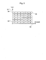
- the deposit counter is part of the Figure 3 explained in more detail.
- Step 22 closes is the step 23 in which it is checked whether the Motor operation for a longer, definable period in a critical operating point has occurred.
- Step 23 Under a critical operating point for a long period of time is a critical mode of operation regarding Understand dirt or deposits. This will be in the Step 23 moored that the difference out current deposit counter AZ and the one in step 22 stored deposit counter a certain, predeterminable threshold has exceeded. Is not this if this is the case, the process is terminated in step 23. is this, on the other hand, is the case where the difference between the current and pre-stored deposit counter a threshold exceeds, step 24 is proceeded to. in the Step 24 is checked analogously to step 21 whether the Engine is in a predetermined operating range. The same operating range is expected as this was already the case in step 21.
- Time of current mixture adaptation values especially the Factor of the mixture adaptation, as described above
- step 27 it is determined in step 26 that a threshold is exceeded, deposits are suspected.
- step 27 is followed by step 27, in which a cleaning mode is activated.
- a cleaning mode For cleaning up there are various possible ways of creating one Deposits can be reduced: e.g. Toggle from Shift operation in homogeneous operation, adjustment of the Ignition angle knocking shortly to generate early Combustion or, for example, a double injection (two injections), the aim of which is to reduce the Valve peak temperature is, which in turn has a positive effect the coking or pollution affects.
- To the Activation of the cleaning mode after step 27 closes the step 28 in which the now after Clean mode available current mixture adaptation values again with those saved after step 22 Mixture adaptation values are compared.
- Figure 3 shows the previously mentioned invention Deposit counter, with a load on a first axis 31 of the engine and on a second axis 32 a speed of Motors is shown.
- the A weighting map is stored in the speed ranges, which in this embodiment consists of discrete factors.
- the engine will be in an appropriate operating range operated, the map value is summed in a certain time grid.
- Examples of different Operating areas are the marked maps of the Weighting map 33, 34 and 35.
- field 33 an operating point with low load and low Speed
- field 34 an operating point with high load and low speed
- field 35 an operating point with high Load and high speed.
- the deposit counter is used to record the times determine to which an evaluation of the mixture adaptation values he follows.
- the time between two evaluation times is variable and is determined by the counter reading of the Deposition counter determined. This ensures that in the time between two evaluations Soiling probability is approximately the same.
- the internal combustion engine was therefore in for a certain time an operating area critical for deposits. This significantly improves the evaluation since the Mixture adaptation values to those resulting in this way Evaluation times become more comparable.
- Control unit 16 can still process the Taking into account additional influences. For example, leakage air has a similar influence on the Mixture adaptation values such as a dirty injector. This can be distinguished from valve contamination be by the mixture adaptation values in the shift and in Homogeneous operation can be compared. Is there such a? Leakage air errors occur, it occurs in shift operation - with throttle valve largely open - no increase the mixture adaptation values.
- Another way to expand the process consists of the mixture adaptation values in different Compare load points. This expansion is based on that a flow reduction at the injector through Contamination almost independent of speed to increase which leads to mixture adaptation values under high load.
Landscapes
- Engineering & Computer Science (AREA)
- Physics & Mathematics (AREA)
- Fluid Mechanics (AREA)
- General Physics & Mathematics (AREA)
- Chemical & Material Sciences (AREA)
- Combustion & Propulsion (AREA)
- Mechanical Engineering (AREA)
- General Engineering & Computer Science (AREA)
- Combined Controls Of Internal Combustion Engines (AREA)
- Electrical Control Of Air Or Fuel Supplied To Internal-Combustion Engine (AREA)
Abstract
Description
- Figur 1
- zeigt ein erfindungsgemäßes Steuergerät sowie eine erfindungsgemäße Brennkraftmaschine,
- Figur 2
- zeigt ein erfindungsgemäßes Verfahren zur Steuerung und/oder Diagnose eines Kraftstoffzumeßsystems einer Brennkraftmaschine, bzw. ein entsprechendes Computerprogramm für eine Brennkraftmaschine, und
- Figur 3
- zeigt ein Detail des erfindungsgemäßen Verfahrens: Eine Ausführungsvariante eines Ablagerungszählers.
Claims (12)
- Verfahren zur Steuerung und/oder Diagnose eines Kraftstoffzumeßsystems einer Brennkraftmaschine, wobei die Brennkraftmaschine eine Gemischadaptionsfunktion aufweist, und wobei Kraftstoff von wenigstens einem Ventil direkt in wenigstens einen Brennraum eingespritzt wird, dadurch gekennzeichnet, dass eine Verschmutzung des Ventils durch eine Auswertung von Ausgangswerten der Gemischadaptionsfunktion erkannt wird.
- Verfahren nach Anspruch 1, dadurch gekennzeichnet, dass die Verschmutzung anhand von steigenden Ausgangswerten der Gemischadaptionsfunktion erkannt wird.
- Verfahren nach Anspruch 1, dadurch gekennzeichnet, dass die Auswertung der Ausgangswerte der Gemischadaptionsfunktion jeweils nach einer variablen Zeitdauer erfolgt.
- Verfahren nach Anspruch 3, dadurch gekennzeichnet, dass die variable Zeitdauer von Betriebspunkten abhängig ist, die während eines Betriebs der Brennkraftmaschine durchlaufen werden.
- Verfahren nach Anspruch 4, dadurch gekennzeichnet, dass den jeweiligen Betriebspunkten eine Wichtung zugeordnet ist, die in Abhängigkeit von einer erwarteten Verschmutzungswahrscheinlichkeit erfolgt.
- Verfahren nach Anspruch 1, dadurch gekennzeichnet, dass eine Auswertung nur dann erfolgt, wenn sich die Brennkraftmaschine zum Auswertungszeitpunkt in einem vorgegebenen Betriebsbereich befindet.
- Verfahren nach Anspruch 1 dadurch gekennzeichnet, dass zur Auswertung gespeicherte Ausgangswerte der Gemischadaptionsfunktion mit aktuellen Werten verglichen werden.
- Verfahren nach Anspruch 1, dadurch gekennzeichnet, dass bei Feststellung einer Verschmutzung gezielt, gegebenenfalls auch wiederholt, Maßnahmen zur Reinigung eingeleitet werden.
- Computerprogramm für eine Brennkraftmaschine eines Kraftfahrzeugs, mit einer Abfolge von Befehlen, die dazu geeignet sind, das Verfahren nach einem der Ansprüche 1 bis 8 durchzuführen, wenn sie auf einem Computer, insbesondere einem Steuergerät für eine Brennkraftmaschine, ausgeführt werden.
- Computerprogramm nach Anspruch 9, wobei die Abfolge von Befehlen auf einem computerlesbaren Datenträger gespeichert ist.
- Steuergerät zur Steuerung und/oder Diagnose eines Kraftstoffzumeßsystems einer Brennkraftmaschine, wobei das Steuergerät eine Gemischadaptionsfunktion aufweist, und wobei Kraftstoff von wenigstens einem Ventil direkt in wenigstens einen Brennraum eingespritzt wird, dadurch gekennzeichnet, dass Mittel vorgesehen sind, um eine Verschmutzung des Ventils durch eine Auswertung von Ausgangswerten der Gemischadaptionsfunktion zu erkennen.
- Brennkraftmaschine mit wenigstens einem Steuergerät zur Steuerung und/oder Diagnose eines Kraftstoffzumeßsystems der Brennkraftmaschine, wobei die Brennkraftmaschine eine Gemischadaptionsfunktion aufweist, und wobei Kraftstoff von wenigstens einem Ventil direkt in wenigstens einen Brennraum eingespritzt wird, dadurch gekennzeichnet, dass Mittel vorgesehen sind, um eine Verschmutzung des Ventils durch eine Auswertung von Ausgangswerten der Gemischadaptionsfunktion zu erkennen.
Applications Claiming Priority (2)
| Application Number | Priority Date | Filing Date | Title |
|---|---|---|---|
| DE10211282 | 2002-03-14 | ||
| DE2002111282 DE10211282A1 (de) | 2002-03-14 | 2002-03-14 | Verfahren zur Steuerung und/oder Diagnose eines Kraftstoffzumesssystems, Computerprogramm, Steuergerät und Brennkraftmaschine |
Publications (3)
| Publication Number | Publication Date |
|---|---|
| EP1344920A2 true EP1344920A2 (de) | 2003-09-17 |
| EP1344920A3 EP1344920A3 (de) | 2005-12-21 |
| EP1344920B1 EP1344920B1 (de) | 2008-03-05 |
Family
ID=27762917
Family Applications (1)
| Application Number | Title | Priority Date | Filing Date |
|---|---|---|---|
| EP20020027052 Expired - Lifetime EP1344920B1 (de) | 2002-03-14 | 2002-12-03 | Verfahren zur Steuerung und/oder Diagnose eines Kraftstoffzumesssystems, Computerprogramm, Steuergerät und Brennkraftmaschine |
Country Status (3)
| Country | Link |
|---|---|
| EP (1) | EP1344920B1 (de) |
| JP (1) | JP2003269226A (de) |
| DE (2) | DE10211282A1 (de) |
Cited By (10)
| Publication number | Priority date | Publication date | Assignee | Title |
|---|---|---|---|---|
| EP1555417A3 (de) * | 2004-01-13 | 2006-11-08 | Toyota Jidosha Kabushiki Kaisha | Vorrichtung zur Steuerung der Einspritzung in einer Brennkraftmaschine |
| WO2008145227A1 (de) | 2007-05-30 | 2008-12-04 | Volkswagen Aktiengesellschaft | Verfahren zum betreiben einer brennkraftmaschine |
| WO2009059854A1 (de) * | 2007-11-09 | 2009-05-14 | Continental Automotive Gmbh | Verfahren und vorrichtung zur durchführung sowohl einer adaption wie einer diagnose bei emissionsrelevanten steuereinrichtungen in einem fahrzeug |
| EP2161435A1 (de) * | 2008-09-09 | 2010-03-10 | Peugeot Citroen Automobiles SA | Verfahren zur Vorhersage des Frühzündungsrisikos eines Verbrennungsmotors |
| FR2993936A1 (fr) * | 2012-07-27 | 2014-01-31 | Peugeot Citroen Automobiles Sa | Procede de caracterisation de l'obstruction d'un injecteur d'un moteur a combustion interne |
| DE102013014674A1 (de) * | 2013-09-04 | 2015-03-05 | Man Diesel & Turbo Se | Verfahren zum Betreiben einer Brennkraftmaschine |
| EP2031222A3 (de) * | 2007-08-31 | 2017-04-26 | Denso Corporation | Kraftstoffeinspritzsystem mit Lernkontrolle zum Ausgleichen der tatsächlichen Einspritzmenge in Bezug auf die Solleinspritzmenge |
| EP3741977A1 (de) * | 2019-05-20 | 2020-11-25 | Mazda Motor Corporation | Motorsteuervorrichtung, motorsteuerverfahren und motorsystem |
| EP3741979A1 (de) * | 2019-05-20 | 2020-11-25 | Mazda Motor Corporation | Motorsteuervorrichtung, motorsteuerverfahren und motorsystem |
| CN113448318A (zh) * | 2021-07-07 | 2021-09-28 | 江铃汽车股份有限公司 | 一种车辆下线故障诊断控制方法 |
Families Citing this family (5)
| Publication number | Priority date | Publication date | Assignee | Title |
|---|---|---|---|---|
| DE102005034449B4 (de) * | 2005-07-23 | 2017-07-06 | Volkswagen Ag | Verfahren und Vorrichtung zur Erkennung von Verkokung an Einspritzdüsen |
| DE102009009796B3 (de) * | 2009-02-20 | 2010-10-07 | L'orange Gmbh | Verfahren zur Diagnose und/oder Steuerung von Brennkraftmaschinen, insbesondere Diesel-Brennkraftmaschinen |
| DE102011085926A1 (de) * | 2011-11-08 | 2013-05-08 | Robert Bosch Gmbh | Verfahren zum Betreiben einer Brennkraftmaschine |
| DE102017217080B4 (de) * | 2017-09-26 | 2021-08-26 | Audi Ag | Verfahren zum Betreiben einer Brennkraftmaschine sowie entsprechende Brennkraftmaschine |
| DE102018106822A1 (de) * | 2018-03-22 | 2019-09-26 | Volkswagen Ag | Regenerationsverfahren zur Reduzierung des Verkokungsgrades eines einen Injektor umgebenden Ringspaltes |
Citations (4)
| Publication number | Priority date | Publication date | Assignee | Title |
|---|---|---|---|---|
| US5181499A (en) | 1991-03-08 | 1993-01-26 | Toyota Jidosha Kabushiki Kaisha | Apparatus for diagnosing abnormality in fuel injection system and fuel injection control system having the apparatus |
| JPH10339196A (ja) | 1997-06-10 | 1998-12-22 | Nissan Motor Co Ltd | 筒内直接噴射式内燃機関 |
| DE19742925C1 (de) | 1997-09-29 | 1999-06-24 | Siemens Ag | Verfahren zum Überwachen eines Einspritzsystems einer Brennkraftmaschine |
| DE19946911A1 (de) | 1999-09-30 | 2001-04-05 | Bosch Gmbh Robert | Verfahren und Vorrichtung zur Überwachung eines Kraftstoffzumeßsystems einer Brennkraftmaschine |
Family Cites Families (3)
| Publication number | Priority date | Publication date | Assignee | Title |
|---|---|---|---|---|
| DE4002208A1 (de) * | 1990-01-26 | 1991-08-01 | Bosch Gmbh Robert | Verfahren zum erkennen von verbrennungsaussetzern bei einem motor |
| DE19945813A1 (de) * | 1999-09-24 | 2001-03-29 | Bosch Gmbh Robert | Verfahren zum Betreiben einer Brennkraftmaschine |
| DE10135735B4 (de) * | 2001-07-21 | 2009-04-16 | Robert Bosch Gmbh | Verfahren zum Betreiben einer Brennkraftmaschine, insbesondere mit Direkteinspritzung, sowie Computerprogramm und Steuer- und/oder Regelgerät |
-
2002
- 2002-03-14 DE DE2002111282 patent/DE10211282A1/de not_active Withdrawn
- 2002-12-03 DE DE50211828T patent/DE50211828D1/de not_active Expired - Fee Related
- 2002-12-03 EP EP20020027052 patent/EP1344920B1/de not_active Expired - Lifetime
-
2003
- 2003-03-14 JP JP2003070116A patent/JP2003269226A/ja not_active Withdrawn
Patent Citations (4)
| Publication number | Priority date | Publication date | Assignee | Title |
|---|---|---|---|---|
| US5181499A (en) | 1991-03-08 | 1993-01-26 | Toyota Jidosha Kabushiki Kaisha | Apparatus for diagnosing abnormality in fuel injection system and fuel injection control system having the apparatus |
| JPH10339196A (ja) | 1997-06-10 | 1998-12-22 | Nissan Motor Co Ltd | 筒内直接噴射式内燃機関 |
| DE19742925C1 (de) | 1997-09-29 | 1999-06-24 | Siemens Ag | Verfahren zum Überwachen eines Einspritzsystems einer Brennkraftmaschine |
| DE19946911A1 (de) | 1999-09-30 | 2001-04-05 | Bosch Gmbh Robert | Verfahren und Vorrichtung zur Überwachung eines Kraftstoffzumeßsystems einer Brennkraftmaschine |
Cited By (17)
| Publication number | Priority date | Publication date | Assignee | Title |
|---|---|---|---|---|
| EP1555417A3 (de) * | 2004-01-13 | 2006-11-08 | Toyota Jidosha Kabushiki Kaisha | Vorrichtung zur Steuerung der Einspritzung in einer Brennkraftmaschine |
| WO2008145227A1 (de) | 2007-05-30 | 2008-12-04 | Volkswagen Aktiengesellschaft | Verfahren zum betreiben einer brennkraftmaschine |
| US7832381B2 (en) | 2007-05-30 | 2010-11-16 | Volkswagen Ag | Method of operating an internal combustion engine |
| EP2031222A3 (de) * | 2007-08-31 | 2017-04-26 | Denso Corporation | Kraftstoffeinspritzsystem mit Lernkontrolle zum Ausgleichen der tatsächlichen Einspritzmenge in Bezug auf die Solleinspritzmenge |
| WO2009059854A1 (de) * | 2007-11-09 | 2009-05-14 | Continental Automotive Gmbh | Verfahren und vorrichtung zur durchführung sowohl einer adaption wie einer diagnose bei emissionsrelevanten steuereinrichtungen in einem fahrzeug |
| CN101855437A (zh) * | 2007-11-09 | 2010-10-06 | 欧陆汽车有限责任公司 | 用于在车辆中的与排放相关的控制装置上既执行匹配又执行诊断的方法和仪器 |
| US8408054B2 (en) | 2007-11-09 | 2013-04-02 | Continental Automotive Gmbh | Method and device for carrying out an adaptation and a diagnosis of emission-relevant control devices in a vehicle |
| CN101855437B (zh) * | 2007-11-09 | 2014-03-26 | 大陆汽车有限公司 | 用于在车辆中的与排放相关的控制装置上既执行匹配又执行诊断的方法和仪器 |
| EP2161435A1 (de) * | 2008-09-09 | 2010-03-10 | Peugeot Citroen Automobiles SA | Verfahren zur Vorhersage des Frühzündungsrisikos eines Verbrennungsmotors |
| FR2935760A1 (fr) * | 2008-09-09 | 2010-03-12 | Peugeot Citroen Automobiles Sa | Procede de prediction du risque de pre-allumage d'un moteur a combustion interne |
| FR2993936A1 (fr) * | 2012-07-27 | 2014-01-31 | Peugeot Citroen Automobiles Sa | Procede de caracterisation de l'obstruction d'un injecteur d'un moteur a combustion interne |
| DE102013014674A1 (de) * | 2013-09-04 | 2015-03-05 | Man Diesel & Turbo Se | Verfahren zum Betreiben einer Brennkraftmaschine |
| EP3741977A1 (de) * | 2019-05-20 | 2020-11-25 | Mazda Motor Corporation | Motorsteuervorrichtung, motorsteuerverfahren und motorsystem |
| EP3741979A1 (de) * | 2019-05-20 | 2020-11-25 | Mazda Motor Corporation | Motorsteuervorrichtung, motorsteuerverfahren und motorsystem |
| US11002215B2 (en) | 2019-05-20 | 2021-05-11 | Mazda Motor Corporation | Engine control device, engine control method, and engine system |
| CN113448318A (zh) * | 2021-07-07 | 2021-09-28 | 江铃汽车股份有限公司 | 一种车辆下线故障诊断控制方法 |
| CN113448318B (zh) * | 2021-07-07 | 2022-08-16 | 江铃汽车股份有限公司 | 一种车辆下线故障诊断控制方法 |
Also Published As
| Publication number | Publication date |
|---|---|
| JP2003269226A (ja) | 2003-09-25 |
| EP1344920B1 (de) | 2008-03-05 |
| DE10211282A1 (de) | 2003-09-25 |
| DE50211828D1 (de) | 2008-04-17 |
| EP1344920A3 (de) | 2005-12-21 |
Similar Documents
| Publication | Publication Date | Title |
|---|---|---|
| EP1218628B1 (de) | Verfahren zum betreiben einer brennkraftmaschine | |
| DE60122255T2 (de) | Erfassung und Ausgleich der Kraftstoffflüchtigkeit beim Kaltstart von einer Brennkraftmaschine | |
| DE102006000197B4 (de) | Kraftstoffeinspritzsteuergerät für einen Verbrennungsmotor mit Zylinderinnenraumeinspritzung | |
| DE102006033869B3 (de) | Verfahren und Vorrichtung zur Diagnose der zylinderselektiven Ungleichverteilung eines Kraftstoff-Luftgemisches, das den Zylindern eines Verbrennungsmotors zugeführt wird | |
| EP1344920B1 (de) | Verfahren zur Steuerung und/oder Diagnose eines Kraftstoffzumesssystems, Computerprogramm, Steuergerät und Brennkraftmaschine | |
| WO2009000647A2 (de) | Verfahren und vorrichtung zur diagnose eines mit einer kraftstoffverteilerleiste in verbindung stehenden einspritzventils einer brennkraftmaschine | |
| DE60015911T2 (de) | Überwachung eines Abgaskatalysators beim Kaltstart | |
| DE19857183A1 (de) | Diagnose einer variablen Ventilsteuerung bei Verbrennungsmotoren | |
| DE102007021283A1 (de) | Verfahren und Vorrichtung zur Ermittlung des Verbrennungs-Lambdawerts einer Brennkraftmaschine | |
| EP2071165B1 (de) | Verfahren und Vorrichtung zum Betreiben einer Brennkraftmaschine | |
| DE10038257A1 (de) | Verfahren zur Diagnose der Funktionstüchtigkeit eines Abgasrückführungssystems einer Brennkraftmaschine | |
| DE102008040857B4 (de) | Steuergerät und Informationserlangungsgerät für ein Abgassystem einer Brennkraftmaschine | |
| WO2017021183A1 (de) | Verfahren zur erkennung fehlerhafter komponenten eines kraftstoffeinspritzsystems | |
| DE4039738C2 (de) | ||
| DE60122657T2 (de) | Vorrichtung und Verfahren zur Diagnose eines Kraftstoffversorgungssystems | |
| DE102006007698B4 (de) | Verfahren zum Betreiben einer Brennkraftmaschine, Computerprogramm-Produkt, Computerprogramm und Steuer- und/oder Regeleinrichtung für eine Brennkraftmaschine | |
| DE102010025662B4 (de) | Verfahren und Vorrichtung zum Betreiben einer Brennkraftmaschine | |
| DE102007026945B4 (de) | Verfahren und Vorrichtung zum Überprüfen eines Abgasrückführsystems und Computerprogramm zur Durchführung des Verfahrens | |
| WO2019120904A1 (de) | Verfahren und vorrichtung zum bestimmen des verschmutzungsgrades eines luftfilters einer verbrennungskraftmaschine | |
| DE19727297A1 (de) | Verfahren zum Betreiben einer Brennkraftmaschine insbesondere eines Kraftfahrzeugs | |
| WO2012055680A1 (de) | Verfahren zur überwachung einer adaption einer einspritzzeit eines einspritzventils einer brennkraftmaschine | |
| DE102016211232A1 (de) | Verfahren zum Erkennen von Rußablagerungen in einem Lufteinlassbereich eines Verbrennungsmotors | |
| DE10153520A1 (de) | Verfahren und Vorrichtung zum Auslesen von Daten eines Kraftstoffzumesssystems | |
| DE102020203662A1 (de) | Verfahren zur Analyse eines Fluids, hierzu eine Vorrichtung mit Mitteln zur Durchführung des Verfahrens sowie ein Computerprogramm, welches ein Ausführen des Verfahrens durch die Vorrichtung bewirkt | |
| DE102016220023B4 (de) | Verfahren und Vorrichtung zur Diagnose eines Gasqualitätssensors für eine gasbetriebene Brennkraftmaschine |
Legal Events
| Date | Code | Title | Description |
|---|---|---|---|
| PUAI | Public reference made under article 153(3) epc to a published international application that has entered the european phase |
Free format text: ORIGINAL CODE: 0009012 |
|
| AK | Designated contracting states |
Kind code of ref document: A2 Designated state(s): AT BE BG CH CY CZ DE DK EE ES FI FR GB GR IE IT LI LU MC NL PT SE SI SK TR |
|
| AX | Request for extension of the european patent |
Extension state: AL LT LV MK RO |
|
| PUAL | Search report despatched |
Free format text: ORIGINAL CODE: 0009013 |
|
| AK | Designated contracting states |
Kind code of ref document: A3 Designated state(s): AT BE BG CH CY CZ DE DK EE ES FI FR GB GR IE IT LI LU MC NL PT SE SI SK TR |
|
| AX | Request for extension of the european patent |
Extension state: AL LT LV MK RO |
|
| 17P | Request for examination filed |
Effective date: 20060621 |
|
| AKX | Designation fees paid |
Designated state(s): DE FR GB IT |
|
| 17Q | First examination report despatched |
Effective date: 20060915 |
|
| GRAP | Despatch of communication of intention to grant a patent |
Free format text: ORIGINAL CODE: EPIDOSNIGR1 |
|
| GRAS | Grant fee paid |
Free format text: ORIGINAL CODE: EPIDOSNIGR3 |
|
| GRAA | (expected) grant |
Free format text: ORIGINAL CODE: 0009210 |
|
| AK | Designated contracting states |
Kind code of ref document: B1 Designated state(s): DE FR GB IT |
|
| REG | Reference to a national code |
Ref country code: GB Ref legal event code: FG4D Free format text: NOT ENGLISH |
|
| REF | Corresponds to: |
Ref document number: 50211828 Country of ref document: DE Date of ref document: 20080417 Kind code of ref document: P |
|
| EN | Fr: translation not filed | ||
| PLBE | No opposition filed within time limit |
Free format text: ORIGINAL CODE: 0009261 |
|
| STAA | Information on the status of an ep patent application or granted ep patent |
Free format text: STATUS: NO OPPOSITION FILED WITHIN TIME LIMIT |
|
| 26N | No opposition filed |
Effective date: 20081208 |
|
| PG25 | Lapsed in a contracting state [announced via postgrant information from national office to epo] |
Ref country code: FR Free format text: LAPSE BECAUSE OF FAILURE TO SUBMIT A TRANSLATION OF THE DESCRIPTION OR TO PAY THE FEE WITHIN THE PRESCRIBED TIME-LIMIT Effective date: 20081226 |
|
| GBPC | Gb: european patent ceased through non-payment of renewal fee |
Effective date: 20081203 |
|
| PG25 | Lapsed in a contracting state [announced via postgrant information from national office to epo] |
Ref country code: IT Free format text: LAPSE BECAUSE OF FAILURE TO SUBMIT A TRANSLATION OF THE DESCRIPTION OR TO PAY THE FEE WITHIN THE PRESCRIBED TIME-LIMIT Effective date: 20080305 |
|
| PG25 | Lapsed in a contracting state [announced via postgrant information from national office to epo] |
Ref country code: DE Free format text: LAPSE BECAUSE OF NON-PAYMENT OF DUE FEES Effective date: 20090701 |
|
| PG25 | Lapsed in a contracting state [announced via postgrant information from national office to epo] |
Ref country code: GB Free format text: LAPSE BECAUSE OF NON-PAYMENT OF DUE FEES Effective date: 20081203 |