EP1344736A2 - Vorrichtung zum Transport von Banknoten - Google Patents
Vorrichtung zum Transport von Banknoten Download PDFInfo
- Publication number
- EP1344736A2 EP1344736A2 EP03004985A EP03004985A EP1344736A2 EP 1344736 A2 EP1344736 A2 EP 1344736A2 EP 03004985 A EP03004985 A EP 03004985A EP 03004985 A EP03004985 A EP 03004985A EP 1344736 A2 EP1344736 A2 EP 1344736A2
- Authority
- EP
- European Patent Office
- Prior art keywords
- belt
- guide means
- guide
- toothed
- curved
- Prior art date
- Legal status (The legal status is an assumption and is not a legal conclusion. Google has not performed a legal analysis and makes no representation as to the accuracy of the status listed.)
- Granted
Links
Images

Classifications
-
- B—PERFORMING OPERATIONS; TRANSPORTING
- B65—CONVEYING; PACKING; STORING; HANDLING THIN OR FILAMENTARY MATERIAL
- B65H—HANDLING THIN OR FILAMENTARY MATERIAL, e.g. SHEETS, WEBS, CABLES
- B65H29/00—Delivering or advancing articles from machines; Advancing articles to or into piles
- B65H29/12—Delivering or advancing articles from machines; Advancing articles to or into piles by means of the nip between two, or between two sets of, moving tapes or bands or rollers
-
- B—PERFORMING OPERATIONS; TRANSPORTING
- B65—CONVEYING; PACKING; STORING; HANDLING THIN OR FILAMENTARY MATERIAL
- B65H—HANDLING THIN OR FILAMENTARY MATERIAL, e.g. SHEETS, WEBS, CABLES
- B65H2301/00—Handling processes for sheets or webs
- B65H2301/40—Type of handling process
- B65H2301/44—Moving, forwarding, guiding material
- B65H2301/443—Moving, forwarding, guiding material by acting on surface of handled material
- B65H2301/4431—Moving, forwarding, guiding material by acting on surface of handled material by means with operating surfaces contacting opposite faces of material
- B65H2301/44312—Moving, forwarding, guiding material by acting on surface of handled material by means with operating surfaces contacting opposite faces of material between belts and rollers
-
- B—PERFORMING OPERATIONS; TRANSPORTING
- B65—CONVEYING; PACKING; STORING; HANDLING THIN OR FILAMENTARY MATERIAL
- B65H—HANDLING THIN OR FILAMENTARY MATERIAL, e.g. SHEETS, WEBS, CABLES
- B65H2404/00—Parts for transporting or guiding the handled material
- B65H2404/20—Belts
- B65H2404/26—Particular arrangement of belt, or belts
- B65H2404/261—Arrangement of belts, or belt(s) / roller(s) facing each other for forming a transport nip
- B65H2404/2611—Arrangement of belts, or belt(s) / roller(s) facing each other for forming a transport nip forming curved transport path
-
- B—PERFORMING OPERATIONS; TRANSPORTING
- B65—CONVEYING; PACKING; STORING; HANDLING THIN OR FILAMENTARY MATERIAL
- B65H—HANDLING THIN OR FILAMENTARY MATERIAL, e.g. SHEETS, WEBS, CABLES
- B65H2404/00—Parts for transporting or guiding the handled material
- B65H2404/20—Belts
- B65H2404/26—Particular arrangement of belt, or belts
- B65H2404/262—Arrangements of belts facing rollers
-
- B—PERFORMING OPERATIONS; TRANSPORTING
- B65—CONVEYING; PACKING; STORING; HANDLING THIN OR FILAMENTARY MATERIAL
- B65H—HANDLING THIN OR FILAMENTARY MATERIAL, e.g. SHEETS, WEBS, CABLES
- B65H2701/00—Handled material; Storage means
- B65H2701/10—Handled articles or webs
- B65H2701/19—Specific article or web
- B65H2701/1912—Banknotes, bills and cheques or the like
Definitions
- the invention relates to a device for transporting banknotes according to the preamble of claim 1.
- the German patent application DE 198 40 420 A1 describes a device for transporting sheet-shaped conveyed goods between a Conveyor belt and a guide means, preferably designed as a roller conveyor, the conveyor belt on the one hand when transporting the conveyed goods and the guide means on the other hand in each case on one of the two opposite Sides of the material to be conveyed.
- the conveyor belt is made up of pressure elements elastically loaded towards the material to be conveyed, so that Material to be conveyed is clamped between the conveyor belt and the guide means and is conveyed by the movement of the conveyor belt.
- the pressure elements are preferably designed as rotatably mounted rollers, which are guided and preloaded by means of leaf springs. This will Reliable sheet material transport is guaranteed with a relatively simple structure.
- banknote checking modules are generally still more compact and robust transport devices with a high height Transport security required.
- the guide means are curved and the belt over the curved Guide means extends and abuts them.
- the strap placed under tension, for example by transmission of a drive torque on the belt and / or by tensioning the belt by means of of a belt tensioner, so arise in the area of the invention curved guide means on which the belt rests, Force components in the direction of the respective guide means.
- the strap is thereby pressed in the direction of the guide means.
- One between the banknote located on the belt and the guide means is thus jammed between the belt and the guide means and through the movement of the belt in one direction of movement of the belt.
- Fig. 1 shows a first embodiment of the device according to the invention in a schematic side view.
- a banknote to be transported 10 is located between a belt 1 during its transport on the one hand and guide means 2 on the other hand, the belt 1 and at least a part of the guide means 2 each on one of the two opposite Sides of banknote 10.
- Banknote 10 The distance between the visible in the schematic representation shown Banknote 10 and strap 1 only serve to improve clarity. In real operation, however, the transport of the banknote is 10 a part of the belt 1 directly against the banknote 10 and presses it against part of the guide means 2, while the other part of the belt 1 the other guide means 2 is present. If there is none in real operation Banknote 10 is located between belt 1 and guide means 2, the Belt 1 directly on the guide means 2.
- the guide means 2 are on one in the direction of movement 11 of the banknote 10 curved path 12 is arranged, which in this example one in has an essential polygonal course.
- the guide means 2 are preferably designed as rollers, which for example pivoted on axles 3 by means of ball or roller bearings are.
- Axles 3 are preferably rigid with a housing (not shown) connected, which carries the device. The axes serve in this Case in addition to the mechanical stabilization and stiffening of the Housing.
- the outer surface 4 of the rollers 2 is preferably a cylindrical outer surface executed.
- a particularly stable lateral guide as a flat belt trained belt 1 perpendicular to the direction of movement 11 is preferred reached when the width of the flat belt is larger than that Width of the rolls 2.
- the effect occurs that a possibly Non-centered flat belts on rollers 2 when commissioning the device automatically due to the occurring forces is centered on the rollers 2.
- the outer surface 4 can also be a concave outer surface, for example in the form of a groove, to ensure a stable lateral belt guide, especially of round belts.
- the angular range over which the belt 1 extends over each individual roll 2 extends is also referred to as the wrap angle and is typically between 7 ° and 20 °, especially around 13 °.
- the guide means designed as rollers have 2 a distance from each other, which is of the order of magnitude Diameter of these rolls. Typical distances are in general at less than about 40 mm. In principle, it is also possible to use the respective Choose roller spacings of different sizes and / or minimize them so far, that the roles are not touching. Form in the latter case the guide means 2 designed as rollers are almost closed Guide path.
- a guide means a closed and in the direction of movement 11 of the banknote 10 curved guide surface (not shown), in particular a guide plate, use.
- curved guide surface interrupted, so that, for example, at predetermined intervals to each other curved guide surface are arranged.
- the surface of the guide surface or the guide plate is preferably designed in such a way that between the banknote 10 to be transported and the guide surface or the friction forces arising from the guide plate are lower than those between the belt 1 and the banknote 10.
- a drive device 20, 21 is provided for driving the belt 1, which transmits a drive torque to the belt 1.
- the drive device 20, 21 is preferably immediate with respect to the direction of movement 11 arranged after the guide means 2 so that the guide means (2) lie in the belt of the belt (1). This is in the area of Guide means 2 drive torque transferred to belt 1 is very large, so that the pressing forces of the belt 1 on the guide means 2 accordingly are high.
- the drive device instructs one a shaft 21 attached drive roller 20.
- the shaft 21 is the Device-bearing housing (not shown) is rotatably mounted and is directly or indirectly, i.e. for example with another strap a drive motor (not shown) coupled.
- Deflection roller 25 is provided for deflecting the belt 1, which in a closed belt run (not shown) running belt 1 leads to the guide means 2.
- Figure 2 shows a second embodiment of the device according to the invention in a schematic side view.
- the guide means 2 and the drive device 20, 21 apply the explanations for the embodiment shown in Fig. 1 accordingly.
- this illustration was omitted the banknote to be transported.
- guide elements 17 and 18 are provided, which are indicated by broken lines.
- a first guiding element 17 is on the side of the guide means 2 and a second guide element 18 arranged on the belt 1 side.
- Guide elements 17 and 18 will be an additional guide to the transported Banknotes achieved, especially at high transport speeds is advantageous because in this case the banknotes flutter can, in turn, lead to an undesirable banknote jam in the transport route can lead.
- the belt 1 is preferably designed as a flat belt.
- the belt 1 is a toothed belt with a first side 14 with a tooth-like profile and a second side 15 without a profile.
- the timing belt is here designed so that it is not stretched or only slightly stretched can.
- this is essentially a belt core made up of a non-stretch material, e.g. a belt made of textile or metal.
- Typical widths of the flat belt are between 5 and 30 mm, in particular at about 15 mm.
- the toothed belt preferably has a division between 1 and 4 mm, especially of about 2 mm.
- the trained as a timing belt Belt 1 is preferably with its second side 15 without a profile on the guide means 2 or on the banknote to be transported (not shown).
- the deflection rollers 25 are preferably one-sided in their peripheral region or provided on both sides with guide walls, which are the side guide serve the belt 1 and thus a particularly stable belt guide guarantee.
- the belt designed as a toothed belt 1 with its first side 14 with a tooth-like profile or with its second side 15 partially wraps around a deflection roller 25 without a profile, this is preferred as a toothed roller or as a roller with a non-profiled peripheral area educated.
- a tensioning device 23 is provided, which in the example shown by means of a spring mechanism against the belt 1 is biased role.
- the tensioning device 23 also displaces the belt 1 under tension, which together with that by the drive device 20 tension generated the power components of the belt 1 in the direction of the guide means 2 or the bank note.
- the elastic pretensioning of the belt 1 by means of the tensioning device 23 has the consequence that the force components generated in the area of the guide means 2 are essentially independent of each on the belt 1 acting load torque. In addition - have neglected lower torque losses on the guide means 2 due to of friction - that by the belt 1 towards the different Guide means 2 acting force components essentially the same Amount.
- a pickup device is in the illustrated embodiment 26 provided in the belt run, which is driven by the belt 1 and in turn can drive other components.
- the customer facility 26 preferably includes a first sprocket, which is driven by the belt 1 designed as a toothed belt.
- To the the first toothed roller is coupled to a second toothed roller, in particular rigidly connected.
- the second toothed roller can then be connected to another toothed belt the transport of banknotes in other components (not shown) Drive banknote processing machine practically without slippage.
- Such a component is, for example, a sensor section, in which individual banknotes to be checked at different Sensors are transported past.
- a sensor section in which individual banknotes to be checked at different Sensors are transported past.
- toothed rollers in the customer device 26 in connection with the drive of the sensor section
- Another toothed belt is used for transport in the sensor section with the transport in the guide means 2 and the belt 1 formed transport route synchronized. This can result in banknote jams or larger gaps between two consecutive banknotes be avoided in the area of the transport route or sensor route.
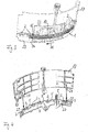
- Fig. 3 shows a further embodiment of the invention in a perspective Presentation.
- a flat toothed belt i.e. as a flat toothed belt
- trained belt 1 lies with its second side 15, which is not Has profile or only a fine profile on the trained as roles Guide means 2 or on the banknote 10 to be transported.
- the Guide means 2 are rotatably mounted on a common carrier 27, which is curved in the direction of movement 11 and one essentially has polygonal shape. This is clearly visible in this illustration first side 14 of the toothed flat belt with its tooth-like profile.
- Banknote 10 is clamped, which is driven by the belt 1 is conveyed in the direction of movement 11.
- a belt 1 is provided, which on the guide means 2 or the banknote 10 is present.
- This device ensures a stable and reliable Banknote transport.
- two or more belts which on corresponding ones arranged in one or more curved paths Management means.
- Fig. 4 shows the embodiment of the invention shown in Fig. 3 in another perspective view.
- the guide means 2 are rotatable mounted on a common support 27, with which on the side the guide means 2 arranged guide element 17 are releasably connected can.
- the illustration shows the carrier 27 and the guide element detached therefrom 17.
- a suitable detachable connection can, for example, by a Plug connection 28, 29 (see arrows) or any other type of detachable connections will be realized. It is possible, alternatively or in addition to Guide element 17 arranged on the side of the belt and detachable with the guide element 27 connected to the carrier (not shown).
- the detachability of the guide element or the guide elements from the carrier 27 becomes easy access to the individual areas and components the transport route for maintenance purposes and / or to remedy Banknote jams enabled.
- rollers Guide means 2 guide webs 5 arranged, which approximately the height of the circumferential surface of the rollers facing the belt and ensure a particularly trouble-free transport of banknotes.
Landscapes
- Engineering & Computer Science (AREA)
- Mechanical Engineering (AREA)
- Delivering By Means Of Belts And Rollers (AREA)
- Feeding Of Articles By Means Other Than Belts Or Rollers (AREA)
Abstract
Description
- Fig. 1
- ein erstes Ausführungsbeispiel der erfindungsgemäßen Vorrichtung in einer schematisierten Seitenansicht;
- Fig. 2
- ein zweites Ausführungsbeispiel der erfindungsgemäßen Vorrichtung in einer schematisierten Seitenansicht;
- Fig. 3
- ein weiteres Ausführungsbeispiel der Erfindung in perspektivischer Darstellung; und
- Fig. 4
- das in Fig. 3 dargestellte Ausführungsbeispiel in einer weiteren perspektivischen Darstellung.
Claims (20)
- Vorrichtung zum Transport von Banknoten mit mindestens einem Riemen (1) und Führungsmitteln (2), wobei beim Transport einer Banknote (10) der Riemen (1) einerseits und die Führungsmittel (2) andererseits jeweils an einer der beiden gegenüberliegenden Seiten der Banknote (10) anliegen, dadurch gekennzeichnet, daß die Führungsmittel (2) gekrümmt ausgeführt sind und sich der Riemen (1) über die gekrümmt ausgeführten Führungsmittel (2) erstreckt und an diesen anliegt.
- Vorrichtung nach Anspruch 1, dadurch gekennzeichnet, daß der Riemen (1) unter Zugspannung an den gekrümmt ausgeführten Führungsmitteln (2) anliegt, so daß die Banknote (10) von dem Riemen (1) gegen die Führungsmittel (2) gedrückt wird.
- Vorrichtung nach einem der Ansprüche 1 bis 2, dadurch gekennzeichnet, daß mindestens eine Antriebseinrichtung (20, 21) zum Antrieb des Riemens (1) vorgesehen ist, welche ein Antriebsmoment auf den Riemen (1) überträgt, wodurch dieser unter Zugspannung versetzt wird.
- Vorrichtung nach Anspruch 3, dadurch gekennzeichnet, daß die Antriebseinrichtung (20, 21) in Bewegungsrichtung (11) der Banknote (10) unmittelbar nach den Führungsmitteln (2) angeordnet ist.
- Vorrichtung nach einem der Ansprüche 1 bis 4, dadurch gekennzeichnet, daß mindestens eine Spanneinrichtung (23) vorgesehen ist, welche den Riemen (1) unter Zugspannung versetzt.
- Vorrichtung nach einem der Ansprüche 1 bis 5, dadurch gekennzeichnet, daß der Riemen (1) als Flachriemen ausgeführt ist.
- Vorrichtung nach einem der Ansprüche 1 bis 6, dadurch gekennzeichnet, daß der Riemen (1) als Zahnriemen ausgeführt ist, welcher eine erste Seite (14) mit einem zahnartigen Profil aufweist.
- Vorrichtung nach Anspruch 7, dadurch gekennzeichnet, daß der Zahnriemen eine zweite Seite (15) ohne Profil aufweist, mit welcher der Zahnriemen an den Führungsmitteln (2) bzw. an der zu transportierenden Banknote (10) anliegt.
- Vorrichtung nach einem der Ansprüche 1 bis 8, dadurch gekennzeichnet, daß die Führungsmittel (2) in Bewegungsrichtung (11) der Banknote (10) gekrümmt ausgeführt sind.
- Vorrichtung nach einem der Ansprüche 1 bis 9, dadurch gekennzeichnet, daß die Führungsmittel (2) auf einer gekrümmten, insbesondere einer polygonal gekrümmten, Bahn (12) angeordnet sind.
- Vorrichtung nach einem der Ansprüche 1 bis 10, dadurch gekennzeichnet, daß die Führungsmittel (2) als Rollen, insbesondere als Kugel- oder Wälzlager, ausgebildet sind.
- Vorrichtung nach einem der Ansprüche 1 bis 11, dadurch gekennzeichnet, daß die Führungsmittel (2) als gekrümmtes Führungsblech ausgebildet sind.
- Vorrichtung nach einem der Ansprüche 1 bis 12, dadurch gekennzeichnet, daß zur zusätzlichen Führung der zu transportierenden Banknote (10) ein oder mehrere Leitelemente (17, 18) vorgesehen sind, welche auf der Seite der Führungsmittel (2) und/oder auf der Seite des Riemens (1) angeordnet sind (17 bzw. 18).
- Vorrichtung nach einem der Ansprüche 1 bis 13, dadurch gekennzeichnet, daß mindestens eine durch den Riemen (1) antreibbare Abnehmereinrichtung (26) vorgesehen ist, welche andere Komponenten antreiben kann.
- Vorrichtung nach Anspruch 14, dadurch gekennzeichnet, daß die Abnehmereinrichtung (26) mindestens eine erste Zahnrolle umfaßt, welche durch den als Zahnriemen ausgeführten Riemen (1) angetrieben werden kann.
- Vorrichtung nach Anspruch 15, dadurch gekennzeichnet, daß die Abnehmereinrichtung (26) mindestens eine zweite Zahnrolle umfaßt, welche mit der ersten Zahnrolle gekoppelt, insbesondere starr verbunden, ist, so daß von der zweiten Zahnrolle ein weiterer Zahnriemen angetrieben werden kann.
- Vorrichtung nach einem der Ansprüche 1 bis 16, dadurch gekennzeichnet, daß eine oder mehrere Umlenkrollen (25) zur Umlenkung des Riemens (1) vorgesehen sind.
- Vorrichtung nach Anspruch 17, dadurch gekennzeichnet, daß mindestens eine Umlenkrolle (25) mindestens eine Führungswand zur seitlichen Führung des Riemens (1) aufweist.
- Vorrichtung nach einem der Ansprüche 1 bis 18, dadurch gekennzeichnet, daß die Führungsmittel (2) an einem gemeinsamen Träger (27) angebracht sind.
- Vorrichtung nach Anspruch 19, dadurch gekennzeichnet, daß der Träger (27) mit einem oder beiden Leitelementen (17, 18) lösbar verbunden ist.
Applications Claiming Priority (2)
| Application Number | Priority Date | Filing Date | Title |
|---|---|---|---|
| DE10210690 | 2002-03-12 | ||
| DE2002110690 DE10210690A1 (de) | 2002-03-12 | 2002-03-12 | Vorrichtung zum Transport von Banknoten |
Publications (3)
| Publication Number | Publication Date |
|---|---|
| EP1344736A2 true EP1344736A2 (de) | 2003-09-17 |
| EP1344736A3 EP1344736A3 (de) | 2005-02-23 |
| EP1344736B1 EP1344736B1 (de) | 2013-05-15 |
Family
ID=27762862
Family Applications (1)
| Application Number | Title | Priority Date | Filing Date |
|---|---|---|---|
| EP03004985.2A Expired - Lifetime EP1344736B1 (de) | 2002-03-12 | 2003-03-11 | Vorrichtung zum Transport von Banknoten |
Country Status (2)
| Country | Link |
|---|---|
| EP (1) | EP1344736B1 (de) |
| DE (1) | DE10210690A1 (de) |
Cited By (2)
| Publication number | Priority date | Publication date | Assignee | Title |
|---|---|---|---|---|
| FR2983842A1 (fr) * | 2011-12-13 | 2013-06-14 | Solystic | Dispositif de convoyage pour objets plats sur chant et machine de tri postal |
| AT514189A1 (de) * | 2013-04-12 | 2014-10-15 | Berndorf Band Gmbh | Vorrichtung mit zumindest einem Endlosband |
Family Cites Families (9)
| Publication number | Priority date | Publication date | Assignee | Title |
|---|---|---|---|---|
| JPS58100043A (ja) * | 1981-12-04 | 1983-06-14 | Nippon Coinco:Kk | 紙幣選別装置 |
| DE3311942A1 (de) * | 1983-03-31 | 1984-10-11 | Computer Gesellschaft Konstanz Mbh, 7750 Konstanz | Transportvorrichtung fuer blatt- oder folienfoermiges transportgut |
| US5499809A (en) * | 1994-05-26 | 1996-03-19 | Kabushiki Kaisha Ace Denken | Bank note conveying apparatus |
| JPH08233037A (ja) * | 1994-12-28 | 1996-09-10 | Mitsuboshi Belting Ltd | 搬送用歯付ベルト |
| GB9517796D0 (en) * | 1995-08-31 | 1995-11-01 | At & T Global Inf Solution | A bank note scanner |
| DE19536480C1 (de) * | 1995-09-29 | 1997-04-17 | Siemens Nixdorf Inf Syst | Antrieb für eine Einrichtung zum Ausgeben von Blattmaterial, insbesondere von Wertscheinen |
| JP3939870B2 (ja) * | 1997-12-15 | 2007-07-04 | 狭山精密工業株式会社 | 貨幣搬送装置 |
| US6367692B1 (en) * | 1998-11-23 | 2002-04-09 | Diebold, Incorporated | Automated transaction machine with removable note storage module |
| FR2799192B1 (fr) * | 1999-10-01 | 2001-11-09 | Poste | Dispositif de distribution automatique de billets de banque ou similaires |
-
2002
- 2002-03-12 DE DE2002110690 patent/DE10210690A1/de not_active Withdrawn
-
2003
- 2003-03-11 EP EP03004985.2A patent/EP1344736B1/de not_active Expired - Lifetime
Cited By (4)
| Publication number | Priority date | Publication date | Assignee | Title |
|---|---|---|---|---|
| FR2983842A1 (fr) * | 2011-12-13 | 2013-06-14 | Solystic | Dispositif de convoyage pour objets plats sur chant et machine de tri postal |
| WO2013088009A1 (fr) | 2011-12-13 | 2013-06-20 | Solystic | Dispositif de convoyage pour objets plats sur chant et machine de tri postal |
| US8893875B2 (en) | 2011-12-13 | 2014-11-25 | Solystic | Conveyor device for conveying flat articles on edge, and a postal sorting machine |
| AT514189A1 (de) * | 2013-04-12 | 2014-10-15 | Berndorf Band Gmbh | Vorrichtung mit zumindest einem Endlosband |
Also Published As
| Publication number | Publication date |
|---|---|
| EP1344736B1 (de) | 2013-05-15 |
| DE10210690A1 (de) | 2003-10-02 |
| EP1344736A3 (de) | 2005-02-23 |
Similar Documents
| Publication | Publication Date | Title |
|---|---|---|
| DE69702583T2 (de) | Verpackungsmaschine | |
| DE2653173C2 (de) | Einrichtung zur Steuerung der Spannung einer kontinuierlich einer taktweise arbeitenden Maschine zugeführten Materialbahn | |
| DE69201043T2 (de) | Übereinander montierte Druckverschliessvorrichtung. | |
| DE2516847A1 (de) | Vorrichtung zum transportieren, zaehlen und/oder entwerten von eintrittskarten o.dgl. | |
| EP0383045A1 (de) | Vorrichtung zum seitlichen Ausrichten einer Stoffkante beim Nähen | |
| DE3883872T2 (de) | Papierzuführvorrichtung für Drucker. | |
| DE3523901A1 (de) | Glasplattenschleifmaschine | |
| DE2633108A1 (de) | Muenzen-sortiervorrichtung | |
| DE69409687T2 (de) | Vorrichtung zum Stapeln von Bogen | |
| EP1061470B1 (de) | Transporteinrichtung für Informationsträger, insbesondere Karten | |
| DE2242993B2 (de) | Transportriementrieb | |
| DE2655098C3 (de) | Belegzuführvorrichtung | |
| EP1080028B1 (de) | Einrichtung zum transportieren von blattförmigem fördergut | |
| DE69014679T2 (de) | Abwickelvorrichtung für Papierrollen. | |
| WO2002062687A2 (de) | Vorrichtung und verfahren zum vereinzeln von blattgut | |
| EP1663829B1 (de) | Vorrichtung zum bearbeiten von blattgut | |
| EP1344736B1 (de) | Vorrichtung zum Transport von Banknoten | |
| DE2624170C3 (de) | Seitenausrichtvorrichtung | |
| DE69525714T2 (de) | Blattzuführeinheit | |
| DE60104820T2 (de) | Dokumentausgabevorrichtung | |
| DE3873906T2 (de) | Drahtfuehrung bei einer drahterosionsbearbeitungsvorrichtung. | |
| DE3636965A1 (de) | Fotopapier-zwischenaufnahmegeraet | |
| DE2928390C2 (de) | Bandtransporteinrichtung für Blätter | |
| DE19536964A1 (de) | Bandantriebsvorrichtung für Umreifungsmaschinen | |
| DE69615320T2 (de) | Einrichtung zum Fördern von gestapelten Dokumenten |
Legal Events
| Date | Code | Title | Description |
|---|---|---|---|
| PUAI | Public reference made under article 153(3) epc to a published international application that has entered the european phase |
Free format text: ORIGINAL CODE: 0009012 |
|
| AK | Designated contracting states |
Kind code of ref document: A2 Designated state(s): AT BE BG CH CY CZ DE DK EE ES FI FR GB GR HU IE IT LI LU MC NL PT RO SE SI SK TR |
|
| AX | Request for extension of the european patent |
Extension state: AL LT LV MK |
|
| PUAL | Search report despatched |
Free format text: ORIGINAL CODE: 0009013 |
|
| RIN1 | Information on inventor provided before grant (corrected) |
Inventor name: STAPFER, MICHAEL |
|
| AK | Designated contracting states |
Kind code of ref document: A3 Designated state(s): AT BE BG CH CY CZ DE DK EE ES FI FR GB GR HU IE IT LI LU MC NL PT RO SE SI SK TR |
|
| AX | Request for extension of the european patent |
Extension state: AL LT LV MK |
|
| 17P | Request for examination filed |
Effective date: 20050823 |
|
| AKX | Designation fees paid |
Designated state(s): AT BE BG CH CY CZ DE DK EE ES FI FR GB GR HU IE IT LI LU MC NL PT RO SE SI SK TR |
|
| 17Q | First examination report despatched |
Effective date: 20060914 |
|
| GRAC | Information related to communication of intention to grant a patent modified |
Free format text: ORIGINAL CODE: EPIDOSCIGR1 |
|
| GRAP | Despatch of communication of intention to grant a patent |
Free format text: ORIGINAL CODE: EPIDOSNIGR1 |
|
| GRAS | Grant fee paid |
Free format text: ORIGINAL CODE: EPIDOSNIGR3 |
|
| GRAA | (expected) grant |
Free format text: ORIGINAL CODE: 0009210 |
|
| AK | Designated contracting states |
Kind code of ref document: B1 Designated state(s): AT BE BG CH CY CZ DE DK EE ES FI FR GB GR HU IE IT LI LU MC NL PT RO SE SI SK TR |
|
| REG | Reference to a national code |
Ref country code: GB Ref legal event code: FG4D Free format text: NOT ENGLISH Ref country code: CH Ref legal event code: EP |
|
| REG | Reference to a national code |
Ref country code: AT Ref legal event code: REF Ref document number: 612039 Country of ref document: AT Kind code of ref document: T Effective date: 20130615 |
|
| REG | Reference to a national code |
Ref country code: IE Ref legal event code: FG4D Free format text: LANGUAGE OF EP DOCUMENT: GERMAN |
|
| REG | Reference to a national code |
Ref country code: DE Ref legal event code: R096 Ref document number: 50314791 Country of ref document: DE Effective date: 20130711 |
|
| REG | Reference to a national code |
Ref country code: NL Ref legal event code: VDEP Effective date: 20130515 |
|
| PG25 | Lapsed in a contracting state [announced via postgrant information from national office to epo] |
Ref country code: FI Free format text: LAPSE BECAUSE OF FAILURE TO SUBMIT A TRANSLATION OF THE DESCRIPTION OR TO PAY THE FEE WITHIN THE PRESCRIBED TIME-LIMIT Effective date: 20130515 Ref country code: GR Free format text: LAPSE BECAUSE OF FAILURE TO SUBMIT A TRANSLATION OF THE DESCRIPTION OR TO PAY THE FEE WITHIN THE PRESCRIBED TIME-LIMIT Effective date: 20130816 Ref country code: SE Free format text: LAPSE BECAUSE OF FAILURE TO SUBMIT A TRANSLATION OF THE DESCRIPTION OR TO PAY THE FEE WITHIN THE PRESCRIBED TIME-LIMIT Effective date: 20130515 Ref country code: SI Free format text: LAPSE BECAUSE OF FAILURE TO SUBMIT A TRANSLATION OF THE DESCRIPTION OR TO PAY THE FEE WITHIN THE PRESCRIBED TIME-LIMIT Effective date: 20130515 Ref country code: PT Free format text: LAPSE BECAUSE OF FAILURE TO SUBMIT A TRANSLATION OF THE DESCRIPTION OR TO PAY THE FEE WITHIN THE PRESCRIBED TIME-LIMIT Effective date: 20130916 Ref country code: ES Free format text: LAPSE BECAUSE OF FAILURE TO SUBMIT A TRANSLATION OF THE DESCRIPTION OR TO PAY THE FEE WITHIN THE PRESCRIBED TIME-LIMIT Effective date: 20130826 |
|
| PG25 | Lapsed in a contracting state [announced via postgrant information from national office to epo] |
Ref country code: BG Free format text: LAPSE BECAUSE OF FAILURE TO SUBMIT A TRANSLATION OF THE DESCRIPTION OR TO PAY THE FEE WITHIN THE PRESCRIBED TIME-LIMIT Effective date: 20130815 |
|
| PG25 | Lapsed in a contracting state [announced via postgrant information from national office to epo] |
Ref country code: CZ Free format text: LAPSE BECAUSE OF FAILURE TO SUBMIT A TRANSLATION OF THE DESCRIPTION OR TO PAY THE FEE WITHIN THE PRESCRIBED TIME-LIMIT Effective date: 20130515 Ref country code: SK Free format text: LAPSE BECAUSE OF FAILURE TO SUBMIT A TRANSLATION OF THE DESCRIPTION OR TO PAY THE FEE WITHIN THE PRESCRIBED TIME-LIMIT Effective date: 20130515 Ref country code: EE Free format text: LAPSE BECAUSE OF FAILURE TO SUBMIT A TRANSLATION OF THE DESCRIPTION OR TO PAY THE FEE WITHIN THE PRESCRIBED TIME-LIMIT Effective date: 20130515 Ref country code: DK Free format text: LAPSE BECAUSE OF FAILURE TO SUBMIT A TRANSLATION OF THE DESCRIPTION OR TO PAY THE FEE WITHIN THE PRESCRIBED TIME-LIMIT Effective date: 20130515 |
|
| PG25 | Lapsed in a contracting state [announced via postgrant information from national office to epo] |
Ref country code: RO Free format text: LAPSE BECAUSE OF FAILURE TO SUBMIT A TRANSLATION OF THE DESCRIPTION OR TO PAY THE FEE WITHIN THE PRESCRIBED TIME-LIMIT Effective date: 20130515 Ref country code: NL Free format text: LAPSE BECAUSE OF FAILURE TO SUBMIT A TRANSLATION OF THE DESCRIPTION OR TO PAY THE FEE WITHIN THE PRESCRIBED TIME-LIMIT Effective date: 20130515 |
|
| PLBE | No opposition filed within time limit |
Free format text: ORIGINAL CODE: 0009261 |
|
| STAA | Information on the status of an ep patent application or granted ep patent |
Free format text: STATUS: NO OPPOSITION FILED WITHIN TIME LIMIT |
|
| 26N | No opposition filed |
Effective date: 20140218 |
|
| REG | Reference to a national code |
Ref country code: DE Ref legal event code: R097 Ref document number: 50314791 Country of ref document: DE Effective date: 20140218 |
|
| PG25 | Lapsed in a contracting state [announced via postgrant information from national office to epo] |
Ref country code: LU Free format text: LAPSE BECAUSE OF FAILURE TO SUBMIT A TRANSLATION OF THE DESCRIPTION OR TO PAY THE FEE WITHIN THE PRESCRIBED TIME-LIMIT Effective date: 20140311 |
|
| REG | Reference to a national code |
Ref country code: CH Ref legal event code: PL |
|
| REG | Reference to a national code |
Ref country code: FR Ref legal event code: ST Effective date: 20141128 |
|
| REG | Reference to a national code |
Ref country code: IE Ref legal event code: MM4A |
|
| PG25 | Lapsed in a contracting state [announced via postgrant information from national office to epo] |
Ref country code: CH Free format text: LAPSE BECAUSE OF NON-PAYMENT OF DUE FEES Effective date: 20140331 Ref country code: LI Free format text: LAPSE BECAUSE OF NON-PAYMENT OF DUE FEES Effective date: 20140331 Ref country code: IE Free format text: LAPSE BECAUSE OF NON-PAYMENT OF DUE FEES Effective date: 20140311 Ref country code: FR Free format text: LAPSE BECAUSE OF NON-PAYMENT OF DUE FEES Effective date: 20140331 |
|
| REG | Reference to a national code |
Ref country code: AT Ref legal event code: MM01 Ref document number: 612039 Country of ref document: AT Kind code of ref document: T Effective date: 20140311 |
|
| PG25 | Lapsed in a contracting state [announced via postgrant information from national office to epo] |
Ref country code: AT Free format text: LAPSE BECAUSE OF NON-PAYMENT OF DUE FEES Effective date: 20140311 |
|
| PG25 | Lapsed in a contracting state [announced via postgrant information from national office to epo] |
Ref country code: MC Free format text: LAPSE BECAUSE OF FAILURE TO SUBMIT A TRANSLATION OF THE DESCRIPTION OR TO PAY THE FEE WITHIN THE PRESCRIBED TIME-LIMIT Effective date: 20130515 |
|
| PG25 | Lapsed in a contracting state [announced via postgrant information from national office to epo] |
Ref country code: CY Free format text: LAPSE BECAUSE OF FAILURE TO SUBMIT A TRANSLATION OF THE DESCRIPTION OR TO PAY THE FEE WITHIN THE PRESCRIBED TIME-LIMIT Effective date: 20130515 |
|
| PG25 | Lapsed in a contracting state [announced via postgrant information from national office to epo] |
Ref country code: HU Free format text: LAPSE BECAUSE OF FAILURE TO SUBMIT A TRANSLATION OF THE DESCRIPTION OR TO PAY THE FEE WITHIN THE PRESCRIBED TIME-LIMIT; INVALID AB INITIO Effective date: 20030311 Ref country code: TR Free format text: LAPSE BECAUSE OF FAILURE TO SUBMIT A TRANSLATION OF THE DESCRIPTION OR TO PAY THE FEE WITHIN THE PRESCRIBED TIME-LIMIT Effective date: 20130515 |
|
| PG25 | Lapsed in a contracting state [announced via postgrant information from national office to epo] |
Ref country code: BE Free format text: LAPSE BECAUSE OF NON-PAYMENT OF DUE FEES Effective date: 20140331 |
|
| REG | Reference to a national code |
Ref country code: DE Ref legal event code: R081 Ref document number: 50314791 Country of ref document: DE Owner name: GIESECKE+DEVRIENT CURRENCY TECHNOLOGY GMBH, DE Free format text: FORMER OWNER: GIESECKE & DEVRIENT GMBH, 81677 MUENCHEN, DE |
|
| REG | Reference to a national code |
Ref country code: GB Ref legal event code: 732E Free format text: REGISTERED BETWEEN 20180118 AND 20180124 |
|
| PGFP | Annual fee paid to national office [announced via postgrant information from national office to epo] |
Ref country code: IT Payment date: 20180322 Year of fee payment: 16 |
|
| PGFP | Annual fee paid to national office [announced via postgrant information from national office to epo] |
Ref country code: DE Payment date: 20190331 Year of fee payment: 17 Ref country code: GB Payment date: 20190325 Year of fee payment: 17 |
|
| PG25 | Lapsed in a contracting state [announced via postgrant information from national office to epo] |
Ref country code: IT Free format text: LAPSE BECAUSE OF NON-PAYMENT OF DUE FEES Effective date: 20190311 |
|
| REG | Reference to a national code |
Ref country code: DE Ref legal event code: R119 Ref document number: 50314791 Country of ref document: DE |
|
| PG25 | Lapsed in a contracting state [announced via postgrant information from national office to epo] |
Ref country code: DE Free format text: LAPSE BECAUSE OF NON-PAYMENT OF DUE FEES Effective date: 20201001 |
|
| GBPC | Gb: european patent ceased through non-payment of renewal fee |
Effective date: 20200311 |
|
| PG25 | Lapsed in a contracting state [announced via postgrant information from national office to epo] |
Ref country code: GB Free format text: LAPSE BECAUSE OF NON-PAYMENT OF DUE FEES Effective date: 20200311 |