EP1344648A2 - Farbwerk für eine Druckmaschine - Google Patents
Farbwerk für eine Druckmaschine Download PDFInfo
- Publication number
- EP1344648A2 EP1344648A2 EP03005022A EP03005022A EP1344648A2 EP 1344648 A2 EP1344648 A2 EP 1344648A2 EP 03005022 A EP03005022 A EP 03005022A EP 03005022 A EP03005022 A EP 03005022A EP 1344648 A2 EP1344648 A2 EP 1344648A2
- Authority
- EP
- European Patent Office
- Prior art keywords
- friction
- drive
- inking unit
- rollers
- drives
- Prior art date
- Legal status (The legal status is an assumption and is not a legal conclusion. Google has not performed a legal analysis and makes no representation as to the accuracy of the status listed.)
- Withdrawn
Links
- 238000007639 printing Methods 0.000 title claims description 5
- 238000007645 offset printing Methods 0.000 claims description 3
- 230000008878 coupling Effects 0.000 claims description 2
- 238000010168 coupling process Methods 0.000 claims description 2
- 238000005859 coupling reaction Methods 0.000 claims description 2
- 238000011161 development Methods 0.000 description 2
- 230000018109 developmental process Effects 0.000 description 2
- 230000015572 biosynthetic process Effects 0.000 description 1
- 238000009826 distribution Methods 0.000 description 1
- 229920001971 elastomer Polymers 0.000 description 1
- 239000003973 paint Substances 0.000 description 1
- 239000005060 rubber Substances 0.000 description 1
Images


Classifications
-
- B—PERFORMING OPERATIONS; TRANSPORTING
- B41—PRINTING; LINING MACHINES; TYPEWRITERS; STAMPS
- B41F—PRINTING MACHINES OR PRESSES
- B41F31/00—Inking arrangements or devices
- B41F31/004—Driving means for ink rollers
-
- B—PERFORMING OPERATIONS; TRANSPORTING
- B41—PRINTING; LINING MACHINES; TYPEWRITERS; STAMPS
- B41F—PRINTING MACHINES OR PRESSES
- B41F31/00—Inking arrangements or devices
- B41F31/15—Devices for moving vibrator-rollers
Definitions
- the invention relates to an inking unit for a printing press, in particular offset printing machine, according to the preamble of Claim 1.
- the color to be printed is from an ink fountain and an ink fountain roller interacting with it, a lifter roller and other inking rollers the inking rollers interacting with a forme cylinder fed.
- One or more of the ink rollers are included formed as a friction roller, which during the rotation also perform axial traverse movements. These traversing movements can also be adjusted in phase and / or stroke be so that the print length becomes noticeable counteracting differences in color density can.
- DE 34 24 721 C2 describes an inking unit of a printing press of the kind briefly outlined above further shown a friction drive, in which a Rotary movement of a disc the axial reciprocation a friction roller is generated.
- the friction rollers of modern offset inking units are not only used for Generation of the axial traversing movement is driven instead also set in rotation. This is necessary to avoid one only by viscosity the paint-driven roller is not strong enough from the surrounding ink rollers, i.e. in certain circumstances unwanted slip occurs.
- the object of the present invention is therefore an inking unit to further develop in accordance with the preamble of claim 1, so that a simple and space-saving drive of a friction roller is possible.
- the drive for the Rotation movement at one end of the friction roller and the drive for the rubbing movement on the opposite one End of the friction roller is arranged.
- both on the A and on the B-side the respective drives for the Rotational movement of the grater or the rubbing movements the grater, each with a traction device in the form of a wedge or other belt drive coupled together and by each driven by a separate drive motor.
- FIG. 1 and 2 show an inking unit, in which with a Form cylinder 1 inking rollers 2 interact.
- the inking rollers 2 stand over friction 3 and further inking rollers 4 with a friction roller 3 in connection, which with a Lifter roller 5 cooperates, which corresponds to the lifter cycle
- Ink is removed from an ink fountain roller 6 and sent to the single drum roller passes.
- the Ends of the grater 3 pulleys 7 on which one Traction means 10 in the form of a toothed belt or multi-groove belt are entwined. So that the pulleys 7 in the intended Ways can be wrapped around by the traction device additionally deflection disks 8 which are fixed to the frame are stored.
- the traction means 10 is also a drive pulley a drive motor 9 looped so that the individual friction rollers 3 together by this motor 9 in Rotation can be driven.
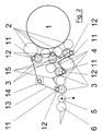
- Figure 2 shows the formation of the inking unit from the opposite Side according to Figure 1.
- individual friction gear 11 At the ends of the friction rollers are arranged individual friction gear 11, in this way are such that a rotating movement of a pulley 12 inside this friction gear 11 in an axial oscillating movement be transmitted.
- the individual friction gear 11 assigned to the rubbers 3 preferably are designed as individual gear blocks - Each have a pulley 12, which of a common traction means 13 are wrapped. For generation the necessary wrap angles are additional pulleys 15 provided fixed to the frame. Furthermore, that is common traction means 13 around a drive pulley of a drive motor 14 out. The drive of the individual friction gears 11 thus takes place from this motor 14.
- Figure 3 shows a grater 3, which at its two ends each a pin 16, 17 in frame walls, not shown a printing press is stored. At one end is the grater 3 rotatably but axially displaceable via a pin 16 connected to a pulley 7, around which the Traction means 10 is looped. On the opposite On the side, the grater 3 has a pin 17, which in the Immersed housing of the friction drive 11. Through this friction gear 11 is the axial traversing movement of the grater 3 embossed - as shown by the double arrows in Figure 3.
- the connection of the friction gear 11 with the pin 17 of the grater 3 is such that only one axial, but not a rotary coupling.
- the friction gear 11 are preferably such that the Stroke and / or the phase of the axial traversing movements independently can be adjusted from each other. So it is possible, each in the inking unit shown in Figures 1 and 2 single friction roller 3 in any way with respect to adjust other graters and make appropriate movements produce. This is a very differentiated response to the different color flow distributions accordingly the subject possible.
Landscapes
- Inking, Control Or Cleaning Of Printing Machines (AREA)
Abstract
Description
- Fig. 1
- die Ansicht eines erfindungsgemäßen Farbwerkes von der einen Seite,
- Fig. 2
- die Ansicht des erfindungsgemäßen Farbwerkes von der gegenüberliegenden Seite, und
- Fig. 3
- eine Reiberwalze mit den an den beiden Enden zugeordneten Antrieben.
- 1
- Formzylinder
- 2
- Farbauftragwalze
- 3
- Reiberwalze
- 4
- Farbwalze
- 5
- Heberwalze
- 6
- Farbkastenwalze
- 7
- Riemenscheibe
- 8
- Umlenkrollen
- 9
- Antriebsmotor (Drehung Reiber 3)
- 10
- Zugmittel
- 11
- Reibergetriebe
- 12
- Riemenscheibe (Reibergetriebe 11)
- 13
- Zugmittel (Reibergetriebe 11)
- 14
- Antriebsmotor (Reibergetriebe 11)
- 15
- Umlenkrollen (Zugmittel 13)
- 16
- Zapfen (Reiber 3)
- 17
- Zapfen (Reiber 3)
Claims (6)
- Farbwerk für eine Druckmaschine, insbesondere eine Offsetdruckmaschine, mit einer Anzahl Farbwalzen und wenigstens einer Reiberwalze, welche jeweils einen Antrieb für die Drehbewegung und für die Verreibungsbewegung aufweist,
dadurch gekennzeichnet, dass der Antrieb für die Drehbewegung an einem Ende der Reiberwalze (3) und der Antrieb für die Verreibungsbewegung an dem gegenüberliegend anderen Ende der Reiberwalze (3) angeordnet ist. - Farbwerk nach Anspruch 1,
dadurch gekennzeichnet, dass bei einem Farbwerk mit mehreren Reiberwalzen (3) die Antriebe (7) für die Drehbewegung auf der jeweils gleichen Seite der Reiber (3) miteinander gekoppelt sind. - Farbwerk nach Anspruch 1,
dadurch gekennzeichnet, dass bei einem Farbwerk mit mehreren Reiberwalzen (3) die Reiberantriebe (11) auf jeweils einer Seite miteinander gekoppelt sind. - Farbwerk nach Anspruch 2 oder 3,
dadurch gekennzeichnet, dass die Kopplung der einzelnen Antriebe (7, 11) der Reiberwalzen (3) über ein Zugmittel (10, 13) erfolgt. - Farbwerk nach Anspruch 1 und 2,
dadurch gekennzeichnet, dass die Reiber (3) an jeweils einem Ende eine Riemenscheibe (7) aufweisen und über ein gemeinsames Zugmittel (10) von einem Antrieb (9) getrieben werden. - Farbwerk nach Anspruch 1 und 3,
dadurch gekennzeichnet, dass die Reiberantriebe (11) jeweils eine Riemenscheibe (12) aufweisen, die über ein gemeinsames Zugmittel (13) von einem Antrieb (14) her antreibbar sind.
Applications Claiming Priority (2)
| Application Number | Priority Date | Filing Date | Title |
|---|---|---|---|
| DE20204255U DE20204255U1 (de) | 2002-03-16 | 2002-03-16 | Farbwerk für eine Druckmaschine |
| DE20204255U | 2002-03-16 |
Publications (2)
| Publication Number | Publication Date |
|---|---|
| EP1344648A2 true EP1344648A2 (de) | 2003-09-17 |
| EP1344648A3 EP1344648A3 (de) | 2004-01-21 |
Family
ID=7969061
Family Applications (1)
| Application Number | Title | Priority Date | Filing Date |
|---|---|---|---|
| EP03005022A Withdrawn EP1344648A3 (de) | 2002-03-16 | 2003-03-06 | Farbwerk für eine Druckmaschine |
Country Status (2)
| Country | Link |
|---|---|
| EP (1) | EP1344648A3 (de) |
| DE (1) | DE20204255U1 (de) |
Citations (1)
| Publication number | Priority date | Publication date | Assignee | Title |
|---|---|---|---|---|
| DE3424721C2 (de) | 1984-07-05 | 1986-12-18 | M.A.N.- Roland Druckmaschinen AG, 6050 Offenbach | Farbwerk für eine Druckmaschine |
Family Cites Families (7)
| Publication number | Priority date | Publication date | Assignee | Title |
|---|---|---|---|---|
| DE312050C (de) * | ||||
| DE139802C (de) * | ||||
| US1464925A (en) * | 1921-03-03 | 1923-08-14 | Miehle Printing Press & Mfg | Ink-distributing-drum-vibrating means |
| US2155354A (en) * | 1936-12-12 | 1939-04-18 | Union Bag & Paper Corp | Inking mechanism for printing presses |
| GB499635A (en) * | 1938-04-14 | 1939-01-26 | Hoe & Co R | Inking mechanism for printing machines |
| DE19505625C2 (de) * | 1995-02-18 | 1996-12-12 | Roland Man Druckmasch | Zwangsantrieb für eine Farbwerkwalze in einer Druckmaschine |
| WO2002081219A2 (de) * | 2001-04-09 | 2002-10-17 | Koenig & Bauer Aktiengesellschaft | Druckwerk einer druckmaschine |
-
2002
- 2002-03-16 DE DE20204255U patent/DE20204255U1/de not_active Expired - Lifetime
-
2003
- 2003-03-06 EP EP03005022A patent/EP1344648A3/de not_active Withdrawn
Patent Citations (1)
| Publication number | Priority date | Publication date | Assignee | Title |
|---|---|---|---|---|
| DE3424721C2 (de) | 1984-07-05 | 1986-12-18 | M.A.N.- Roland Druckmaschinen AG, 6050 Offenbach | Farbwerk für eine Druckmaschine |
Also Published As
| Publication number | Publication date |
|---|---|
| DE20204255U1 (de) | 2002-05-16 |
| EP1344648A3 (de) | 2004-01-21 |
Similar Documents
| Publication | Publication Date | Title |
|---|---|---|
| EP1441905A1 (de) | Antrieb eines druckwerkes | |
| DE4021895A1 (de) | Druckeinheit zur durchfuehrung eines fliegenden druckplattenwechsels | |
| DE3918128C2 (de) | ||
| DE2902228C2 (de) | Vorrichtung zum Zuführen von Flüssigkeit zum Plattenzylinder einer Offset-Rotationsdruckmaschine | |
| DE3614029C1 (de) | Rollenrotations-Offsetdruckmaschine mit einem Druckwerk fuer fliegenden Plattenwechsel | |
| DE3143781C2 (de) | Vorrichtung zum Zuführen einer Flüssigkeit auf die Zylinder einer Rotationdruckmaschine | |
| EP0818309A2 (de) | Separate Antriebe einer Flexodruckmaschine | |
| EP0727312A2 (de) | Antriebsvorrichtung für eine Walze, vorzugsweise in Offsetdruckmaschinen | |
| EP0707958B1 (de) | Vorrichtung zum Beseitigen von Zahnspiel | |
| EP2127874B1 (de) | Verfahren zum Betreiben einer Druckmaschine | |
| DE3203803C1 (de) | Antriebsvorrichtung fuer die Reibwalzen eines Farb- und Feuchtwerkes einer Rotationsdruckmaschine | |
| EP0480879B1 (de) | Vorrichtung zur stufenlosen Verstellung der axialen Verreibungsbewegung von Reibwalzen | |
| DE3008981A1 (de) | Umstellbares heber-/filmfarbwerk | |
| EP1361055B1 (de) | Verreibungsantrieb für eine Walze | |
| EP2114681B1 (de) | Druckwerk einer rotationsdruckmaschine und ein verfahren zum waschen eines feuchtwerks eines druckwerks | |
| DE3407428C1 (de) | Anordnung zum Antrieb einer Walze oder eines Zylinders einer von Buchdruck auf Flexodruck umruestbaren Rotationsdruckmaschine | |
| DE20204255U1 (de) | Farbwerk für eine Druckmaschine | |
| DE4012292A1 (de) | Heber-schaltgetriebe an farbwerken von druckmaschinen | |
| DE10211328B4 (de) | Vorrichtung zum Anstellen einer Walze an ein sich im wesentlichen mit der Umfangsgeschwindigkeit der Walze bewegtes Widerlager mittels einer Spindel-Spindelmutter-Paarung | |
| DE10163961A1 (de) | Antrieb eines Druckwerkes | |
| DE102009045922B4 (de) | Vorrichtung in einem Druckwerk einer Druckmaschine | |
| DE10163962B4 (de) | Antrieb eines Druckwerkes | |
| DE10143871C1 (de) | Farbwerk für eine Druckmaschine | |
| DE69805512T2 (de) | Flexodruckmaschine | |
| DE2948383A1 (de) | Antrieb fuer mehrfarbenbogenrotationsdruckmaschinen |
Legal Events
| Date | Code | Title | Description |
|---|---|---|---|
| PUAI | Public reference made under article 153(3) epc to a published international application that has entered the european phase |
Free format text: ORIGINAL CODE: 0009012 |
|
| AK | Designated contracting states |
Kind code of ref document: A2 Designated state(s): AT BE BG CH CY CZ DE DK EE ES FI FR GB GR HU IE IT LI LU MC NL PT RO SE SI SK TR |
|
| AX | Request for extension of the european patent |
Extension state: AL LT LV MK |
|
| PUAL | Search report despatched |
Free format text: ORIGINAL CODE: 0009013 |
|
| AK | Designated contracting states |
Kind code of ref document: A3 Designated state(s): AT BE BG CH CY CZ DE DK EE ES FI FR GB GR HU IE IT LI LU MC NL PT RO SE SI SK TR |
|
| AX | Request for extension of the european patent |
Extension state: AL LT LV MK |
|
| 17P | Request for examination filed |
Effective date: 20031218 |
|
| AKX | Designation fees paid |
Designated state(s): AT BE BG CH CY CZ DE DK EE ES FI FR GB GR HU IE IT LI LU MC NL PT RO SE SI SK TR |
|
| RAP1 | Party data changed (applicant data changed or rights of an application transferred) |
Owner name: MANROLAND AG |
|
| 17Q | First examination report despatched |
Effective date: 20091218 |
|
| STAA | Information on the status of an ep patent application or granted ep patent |
Free format text: STATUS: THE APPLICATION HAS BEEN WITHDRAWN |
|
| 18W | Application withdrawn |
Effective date: 20100324 |