EP1342850A2 - Strassendeckenschneidegerät - Google Patents
Strassendeckenschneidegerät Download PDFInfo
- Publication number
- EP1342850A2 EP1342850A2 EP02017274A EP02017274A EP1342850A2 EP 1342850 A2 EP1342850 A2 EP 1342850A2 EP 02017274 A EP02017274 A EP 02017274A EP 02017274 A EP02017274 A EP 02017274A EP 1342850 A2 EP1342850 A2 EP 1342850A2
- Authority
- EP
- European Patent Office
- Prior art keywords
- wheel
- arm
- cutting
- wheels
- circular
- Prior art date
- Legal status (The legal status is an assumption and is not a legal conclusion. Google has not performed a legal analysis and makes no representation as to the accuracy of the status listed.)
- Withdrawn
Links
- 238000005520 cutting process Methods 0.000 claims abstract description 131
- 238000000034 method Methods 0.000 description 3
- 238000010276 construction Methods 0.000 description 1
- XLYOFNOQVPJJNP-UHFFFAOYSA-N water Substances O XLYOFNOQVPJJNP-UHFFFAOYSA-N 0.000 description 1
- 230000003245 working effect Effects 0.000 description 1
Images


Classifications
-
- E—FIXED CONSTRUCTIONS
- E01—CONSTRUCTION OF ROADS, RAILWAYS, OR BRIDGES
- E01C—CONSTRUCTION OF, OR SURFACES FOR, ROADS, SPORTS GROUNDS, OR THE LIKE; MACHINES OR AUXILIARY TOOLS FOR CONSTRUCTION OR REPAIR
- E01C23/00—Auxiliary devices or arrangements for constructing, repairing, reconditioning, or taking-up road or like surfaces
- E01C23/06—Devices or arrangements for working the finished surface; Devices for repairing or reconditioning the surface of damaged paving; Recycling in place or on the road
- E01C23/09—Devices or arrangements for working the finished surface; Devices for repairing or reconditioning the surface of damaged paving; Recycling in place or on the road for forming cuts, grooves, or recesses, e.g. for making joints or channels for markings, for cutting-out sections to be removed; for cleaning, treating, or filling cuts, grooves, recesses, or fissures; for trimming paving edges
- E01C23/0906—Devices or arrangements for working the finished surface; Devices for repairing or reconditioning the surface of damaged paving; Recycling in place or on the road for forming cuts, grooves, or recesses, e.g. for making joints or channels for markings, for cutting-out sections to be removed; for cleaning, treating, or filling cuts, grooves, recesses, or fissures; for trimming paving edges for forming, opening-out, cleaning, drying or heating cuts, grooves, recesses or, excluding forming, cracks, e.g. cleaning by sand-blasting or air-jet ; for trimming paving edges
- E01C23/0926—Devices or arrangements for working the finished surface; Devices for repairing or reconditioning the surface of damaged paving; Recycling in place or on the road for forming cuts, grooves, or recesses, e.g. for making joints or channels for markings, for cutting-out sections to be removed; for cleaning, treating, or filling cuts, grooves, recesses, or fissures; for trimming paving edges for forming, opening-out, cleaning, drying or heating cuts, grooves, recesses or, excluding forming, cracks, e.g. cleaning by sand-blasting or air-jet ; for trimming paving edges with power-driven tools, e.g. vibrated, percussive cutters
- E01C23/0933—Devices or arrangements for working the finished surface; Devices for repairing or reconditioning the surface of damaged paving; Recycling in place or on the road for forming cuts, grooves, or recesses, e.g. for making joints or channels for markings, for cutting-out sections to be removed; for cleaning, treating, or filling cuts, grooves, recesses, or fissures; for trimming paving edges for forming, opening-out, cleaning, drying or heating cuts, grooves, recesses or, excluding forming, cracks, e.g. cleaning by sand-blasting or air-jet ; for trimming paving edges with power-driven tools, e.g. vibrated, percussive cutters rotary, e.g. circular-saw joint cutters
-
- B—PERFORMING OPERATIONS; TRANSPORTING
- B62—LAND VEHICLES FOR TRAVELLING OTHERWISE THAN ON RAILS
- B62D—MOTOR VEHICLES; TRAILERS
- B62D7/00—Steering linkage; Stub axles or their mountings
- B62D7/06—Steering linkage; Stub axles or their mountings for individually-pivoted wheels, e.g. on king-pins
- B62D7/08—Steering linkage; Stub axles or their mountings for individually-pivoted wheels, e.g. on king-pins the pivotal axes being situated in a single plane transverse to the longitudinal centre line of the vehicle
Definitions
- the present invention relates to a cutting apparatus for cutting paved roads equipped with a wheel angle shift mechanism for shifting a circular cutting position to a straight cutting position and vice versa, and for fixing the position afterward, which is capable of being operated by a one-touch handling.
- Cutting apparatuses for cutting paved roads used in roads constructions and the like have been known as disclosed in (1) Japanese laid open patent No.7-279118, (2) Japanese laid open patent No.63-55204, (3) Japanese laid open utility model No.3-72904 and so forth.
- example (1) since the cutter driving unit and the main body of the apparatus are arranged outside of the cutting circle, the apparatus requires a wide area for cutting operations.
- example (2) though the arrangement of the apparatus is simple such that the driving unit is directly connected to the revolving axis of the cutter, it is less practical in its maneuverability and operability.
- example (3) the steering device for sifting circular/straight cutting is arranged in the apparatus.
- the apparatus has a problem in its maneuverability, when it is used for circular cuttings.
- the applicant already filed a patent (the Japanese laid open patent No.2001-29516) relating to a cutting apparatus for cutting paved roads.
- the patent discloses a fairly compact apparatus for cutting paved roads by arranging the cutter and the apparatus inside the cutting circle. Since upright revolving axes of wheels supporting the apparatus are arranged inside of wheels in an offset state, the apparatus can be moved in accordance with a circular or straight cutting mode. In addition, in order to improve a moving stability of the apparatus, the revolving axis of the cutter is positioned between front wheels and rear wheels.
- the proposed apparatus is equipped with a wheel angle shift mechanism capable of shifting a circular cutting position to a straight cutting position and vice versa, and for fixing the position afterward by determining a geometric arrangement among components of the wheel angle shift mechanism based on arithmetic calculations.
- the present invention is carried out in view of the above-mentioned problems in order to provide a cutting apparatus for cutting paved roads circularly or straightly having a wheel angle shift mechanism capable of shifting a circular cutting position to a straight cutting position and vice versa, and for fixing the position afterward through simple operations by arranging components of the apparatus based on arithmetic calculations, basically using trigonometric functions and inverse trigonometric functions.
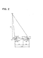
- the cutting apparatus for cutting paved roads by the present invention comprises an engine unit to rotate spherical shell shaped disk cutters Ct1 and Ct2 for the circular cutting, and a chassis BS equipped with wheels for moving the cutting apparatus circularly or straightly.
- the engine unit is mounted on the chassis BS and arranged inside the cutting radius of the cutter, and equipped with the tilting device KE.
- a rotating axis 7 of the cutter is arranged between front wheels and rear wheels of the cutting apparatus.
- two pairs of front wheels are arranged respectively for exclusive uses, namely one pair for the straight movement is switched to the another pair for the circular movement and vice versa by a handle (not shown).
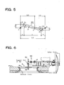
- the cutting radius is changeable or adjustable, for example, from R1 to R2 or from R2 to R1 (see FIG.1) by a slider 9 which moves along the rotating axis 7 of the cutter in a radial direction of the cutting circle as shown in FIG.6.
- a support axis 8a is detachably inserted to the support point S0, which functions as the cutting center, of the chassis BS.
- the lower end of the support axis 8a is inserted into a center hole of a flat disk cover 8b, which constitute a centering jig 8 for determining the cutting center.
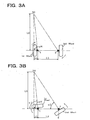
- a pair of the rear wheels comprising the first wheel and the second wheel, are used for the circular or straight movement of the cutting apparatus by handling a wheel angle shift mechanism K.
- the wheel angle shift mechanism K comprises a first arm attached to the first wheel, a second arm attached to the second wheel, a third arm connected to the first arm and to the second arm, and a shift lever 5.
- Respective vertical revolving axes 1 and 2 of the first and second wheels are arranged at offset positions such that the respective revolving axes 1 and 2 are facing each other inside of and in the vicinity of the first and second wheels.
- respective vertical revolving axes are inserted into and supported by cylinder bearings 1a and 2a vertically fixed to a base frame (not shown) of the chassis BS so as to revolve horizontally.
- the above-mentioned mutually facing first and second wheels for the circular or straight movement can be shifted from the straight cutting angles to the circular cutting angles and determined their respective angles afterward, and vice versa by a one-touch handling of the shift lever 5.
- the first wheel is arranged on a radial line from the support point S0 and is used as an inner wheel during the circular movement.
- the second wheel is arranged apart from the first wheel by a determined distance so as to face each other and is used as an outer wheel during the circular movement.
- the first and second wheels respectively have the first arm and the second arm formed as blocks, fixed to respective revolving axes 1 and 2 formed at offset positions from the wheels, where the first and second arms are indirectly connected via the third arm.
- An arm support axis 4 is formed at the middle position of the third arm so that the third arm is rotatably fixed to a bracket 6 of the chassis BS.
- the wheel angles from the circular movement to the straight movement can be shifted easily by the shift lever 5 arranged at the upper portion of the revolving axis 1 attached to the first wheel such that angles of the first and second wheels on circles around support point S0 can be adjusted and determined.
- the shift lever 5 is shifted in a reverse direction, the wheel angles are shifted from the straight movement to the circular movement.
- the support point S0 is formed so as to cross a support axis of the tilting device KE.
- the tilting device KE is arranged so as to be slidably moved along the revolving axis 7 of the cutter and its position is determined by handling the slider 9, when the cutting radius is shifted from R1 to R2 respectively corresponding to the spherical shell shaped disks Ct1 and Ct2.
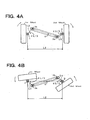
- a distance of a vertical line from the support point S0 of the chassis BS, as the revolving center of the circular cutting, to a base line connecting the revolving axis 1 and the revolving axis 2, is defined as L0.
- a distance from the revolving axis 1 of the first wheel to the above-mentioned vertical line from the support point S0 of the chassis BS is defined as L1.
- a distance between the revolving axes 1 and 2 of the first and second wheels is defined as L2.
- a distance between the revolving axis 1 and a connecting point 3a, where the first arm and the third arm are connected, is defined as L3.
- a distance between the revolving axis 2 and a connecting point 3b, where the second arm and the third arm are connected, is defined as L4.
- a shifted angle of the first arm when revolving the third arm around the arm support axis 4 arranged at the middle of the third arm for shifting the wheel angle, is defined as ⁇ 1.
- a shifted angle of the second arm is defined as ⁇ 2.
- Distances a, b, c, d and e, depicted in FIG.5 are respectively defined as follows.
- Distance a a projected distance of L3 on the base line
- distance b a projected distance of L4 on the base line
- distance c a projected distance between the connecting points 3a and 3b on the base line
- distance d a projected distance of L3 on a vertical line to the base line
- distance e a projected distance of L4 on a vertical line to the base line.
- L6 is calculated in the same way as L5.
- L6 [(L4 ⁇ sin ⁇ 2)/ sin ( ⁇ 2 + ⁇ 2/2)]
- the wheel angle shifting mechanism capable of shifting circular/straight cutting by the one-touch handling can be arranged accurately.
- respective pairs of front and rear wheels are arranged on the cutting apparatus, but a cutting apparatus with one front wheel, namely, a three-wheeled cutting apparatus is also possible.
- the four-wheeled cutting apparatus is better than the three-wheeled cutting apparatus for a stable circular cutting operation.
- two cutting diameters for the circular cutting are selected based on sizes of manholes employed in water supply and drainage systems, underground power supply systems, gas supply systems, underground telephone networks and the like in Japan.
- a radius R1 depicted in FIG. 1 corresponds to a 1m cutting diameter, which means the spherical shell shaped disk cutter Ct1 forms a portion of a sphere with a 500mm radius.
- a radius R2 corresponds to a 1.2m cutting diameter, which means the spherical shell shaped disk cutter Ct2 forms a portion of a sphere of a 600mm radius.
- a pair of front wheels for the straight movement and another pair of front wheels for the circular movements are arranged independently. Both pairs of front wheels are arranged for being lifted by the handle (not shown) so that either one of pairs can be selected for straight or circular cutting operations. The cutter for the straight cutting is exchanged to the cutter for the circular cutting and vice versa in accordance with the selected pair of front wheels.
- the cutting apparatus After arranging the cutting apparatus to meet conditions of a cutting site, it is transported to the site.
- the cutting diameter is 1m, namely, R1 is 500mm
- the cutter Ct1 forming a portion of the sphere with the 500mm radius is fitted to a predetermined position of the cutting apparatus.
- the engine unit for driving the cutter is lifted upward by a handle (not shown) of the tilting mechanism KE (FIG.7a).
- the cutter itself is positioned apart from a road surface of the site.
- the flat disk cover 8b of the centering jig 8 with a corresponding size to the removed manhole cover is temporarily fitted to the manhole.
- a locking mechanism (not shown) to lock the shifted angles is arranged in the shift lever 5.
- the locked shift lever 5 is unlocked when the shift lever 5 is raised with a predetermined distance so that the shift lever 5 is revolved to the left or to the right and is shifted to the circular cutting position or straight cutting position, then the shift lever 5 is returned to a horizontal position and locked for the next one-touch shift handling.
- the raised cutter Ct1 is lowered by handling the tilting mechanism KE until a blade arranged on a periphery of the cutter is contacted to a predetermined position of the road (see FIG.8). Then a switch of the engine unit is switched on so as to drive the cutter Ct1 for cutting the road up to a predetermined depth (in this stage the revolving axis 7 is positioned almost horizontally). After setting a pair of the front wheels for circular cutting and when the apparatus is moved forward by pushing a gripping handle (not shown) of the cutting apparatus, a precise and smooth circular cutting is executed due to setting the wheel angle shift mechanism K at the circular movement.
- the shift lever 5 When transferring the cutting apparatus as well as when cutting straightly, the shift lever 5 is shifted from the circular cutting to the original position by the one-touch handling so as to work the wheel angle shift mechanism K, so that the first wheel is revolved reversely by ⁇ 1 (86.75°), simultaneously the second wheel is revolved reversely by ⁇ 2 (53.47°), thus the first and second wheels are set at a parallel position depicted by solid lines as shown in FIG.1.
- the cutting radius of the cutting circle can be changed/adjusted by the slider 9 which enables the engine unit together with the cutter move along the revolving axis 7 of the cutter arranged on a diameter of the cutting circle, as the support point S0 of the chassis BS, the center of the revolving (or cutting circle), being fixed.
- the centering jig 8 is arranged such that the support axis 8a is detachably inserted into a hole forming the support point S0 of the chassis BS and a lower portion of the support axis 8a is inserted into the center of the flat disk cover 8b. If the flat disk cover 8b with a size corresponding to a size of the manhole at the cutting site is selected beforehand, a centering procedure for the circular cutting operation is executed without difficulties. The centering procedure is also carried out by employing anchor bolts or the like in place of utilizing the manhole cover.
- the cutting apparatus Since the cutting apparatus is formed so compact that the whole body of the cutting apparatus can be accommodated within the cutting circle with the 1m diameter, the cutting machine shows its excellent performance without any practical difficulties. The reason is why the compactly arranged cutting apparatus does not extend to an area where a level difference between the road to be cut and a footpath exists, even when there is such difference.
- the cutting apparatus has mutually changeable two independent pairs of front wheels respectively for the straight movement and the circular movement, and since wheel angles of a pair of the rear wheels can be changed by the one-touch handling, precise straight or circular forward/backward movements of the cutting machine are attained without getting out of predetermined tracks. Consequently, a working performance and an operating performance of the cutting apparatus are raised up to almost their limits.
- the present invention can provide an excellent cutting apparatus for cutting paved roads having the following features: the support point as the cutting center is arranged at a position apart a little from the chassis; the wheel angle shift mechanism for shifting from the straight to circular movement and vice versa capable of being operated by the one-touch handling is arranged; the geometric relations among components of the wheel angle shift mechanism is determined by trigonometric and inverse trigonometric functions; the number of the components is reduced; a rigidity of the cutting apparatus is raised; stable movements are attained by arranging the front wheels on one side of the revolving axis of the cutter and arranging the rear wheels on the opposite side; and improved working/operating performances and less expensive apparatus are attained by the compact arrangement.
- the wheel angle shift mechanism is arranged such that wheel angles for circular/straight movements during circular/straight cuttings are changed and set by the one-touch handling.
- the geometric relations among components of the wheel angle shift mechanism are theoretically determined by trigonometric and inverse trigonometric functions so as to carry out determining and fixing wheel angles precisely.
- the rigidity of the cutting apparatus is raised. Stable movements are attained by arranging the front wheels on one side of the revolving axis of the cutter and arranging the rear wheels on the opposite side. Working/operating performances are improved. Less expensive cutting apparatus is obtained by reducing the number of components.
Landscapes
- Engineering & Computer Science (AREA)
- Mining & Mineral Resources (AREA)
- Architecture (AREA)
- Civil Engineering (AREA)
- Structural Engineering (AREA)
- Chemical & Material Sciences (AREA)
- Combustion & Propulsion (AREA)
- Transportation (AREA)
- Mechanical Engineering (AREA)
- Road Repair (AREA)
- Harvester Elements (AREA)
Applications Claiming Priority (2)
| Application Number | Priority Date | Filing Date | Title |
|---|---|---|---|
| JP2002060514 | 2002-03-06 | ||
| JP2002060514 | 2002-03-06 |
Publications (2)
| Publication Number | Publication Date |
|---|---|
| EP1342850A2 true EP1342850A2 (de) | 2003-09-10 |
| EP1342850A3 EP1342850A3 (de) | 2004-04-21 |
Family
ID=27751137
Family Applications (1)
| Application Number | Title | Priority Date | Filing Date |
|---|---|---|---|
| EP02017274A Withdrawn EP1342850A3 (de) | 2002-03-06 | 2002-08-01 | Strassendeckenschneidegerät |
Country Status (1)
| Country | Link |
|---|---|
| EP (1) | EP1342850A3 (de) |
Citations (4)
| Publication number | Priority date | Publication date | Assignee | Title |
|---|---|---|---|---|
| JPS6355204A (ja) | 1985-09-17 | 1988-03-09 | 日本電信電話株式会社 | 舗装路面切断ブレードおよび切断ブレードを用いた路面の円形切断装置 |
| JPH0372904U (de) | 1989-11-17 | 1991-07-23 | ||
| JPH07279118A (ja) | 1994-04-14 | 1995-10-24 | Taikei Kensetsu Kk | 路面の切断方法および路面切断装置 |
| JP2001029516A (ja) | 2000-01-01 | 2001-02-06 | Konii & San Enterprise:Kk | ゴルフクラブのトルク測定用ロボット |
Family Cites Families (5)
| Publication number | Priority date | Publication date | Assignee | Title |
|---|---|---|---|---|
| FR523422A (fr) * | 1920-01-17 | 1921-08-18 | David Henri Wolkowitsch | Système perfectionné de braquage des roues directrices de véhicules automobiles et autres circulant sur route |
| US3528682A (en) * | 1968-05-14 | 1970-09-15 | Marx & Co Louis | Steering device for vehicles |
| JPS6053469A (ja) * | 1983-08-31 | 1985-03-27 | Kubota Ltd | 車両のステアリング装置 |
| JPS60193769A (ja) * | 1984-03-14 | 1985-10-02 | Nippon Yusoki Co Ltd | かじ取機構 |
| JP3371254B2 (ja) * | 2000-02-10 | 2003-01-27 | 志賀産業株式会社 | 路面用カッター |
-
2002
- 2002-08-01 EP EP02017274A patent/EP1342850A3/de not_active Withdrawn
Patent Citations (4)
| Publication number | Priority date | Publication date | Assignee | Title |
|---|---|---|---|---|
| JPS6355204A (ja) | 1985-09-17 | 1988-03-09 | 日本電信電話株式会社 | 舗装路面切断ブレードおよび切断ブレードを用いた路面の円形切断装置 |
| JPH0372904U (de) | 1989-11-17 | 1991-07-23 | ||
| JPH07279118A (ja) | 1994-04-14 | 1995-10-24 | Taikei Kensetsu Kk | 路面の切断方法および路面切断装置 |
| JP2001029516A (ja) | 2000-01-01 | 2001-02-06 | Konii & San Enterprise:Kk | ゴルフクラブのトルク測定用ロボット |
Also Published As
| Publication number | Publication date |
|---|---|
| EP1342850A3 (de) | 2004-04-21 |
Similar Documents
| Publication | Publication Date | Title |
|---|---|---|
| US6425638B1 (en) | Pavement cutter | |
| CA1172299A (en) | Excavator | |
| AU2003200696A1 (en) | Cutting apparatus for cutting paved road | |
| US4627499A (en) | Mobile drilling machine | |
| EP1342850A2 (de) | Strassendeckenschneidegerät | |
| JP3893367B2 (ja) | 路面用円形カッター | |
| KR20090071205A (ko) | 휠 타입 굴삭기의 접지위치 가변형 아웃트리거 | |
| JP2007009540A (ja) | 路面切削装置 | |
| JP3489616B2 (ja) | コンクリート壁構造物の撤去方法 | |
| CN214816244U (zh) | 一种海底管道海上焊接辅助对口器 | |
| JP4352382B2 (ja) | トンネル壁面の切削装置 | |
| JP3419693B2 (ja) | マンホールの周囲の舗装面の切削装置と切削機 | |
| JP2000313587A (ja) | 移動装置 | |
| JP3445948B2 (ja) | 穿孔機 | |
| SE415586B (sv) | Anordning for nergrevning av en pa sjobottnen utlagd rorledning | |
| CN213572106U (zh) | 多功能水泥开沟机 | |
| JP2006029015A (ja) | 側溝の側壁切断装置 | |
| JPS6315416B2 (de) | ||
| JPS5810779Y2 (ja) | シヨベル作業車 | |
| JP3126241U (ja) | 舗装路面切断装置 | |
| JP2001003311A (ja) | 切削装置 | |
| JP2002021075A (ja) | 縦穴掘削機の回転反力伝達機構 | |
| JP2001271310A (ja) | 道路はつり機 | |
| JPS5976335A (ja) | 溝掘削機 | |
| JPH02252889A (ja) | トンネル内壁面掘削機 |
Legal Events
| Date | Code | Title | Description |
|---|---|---|---|
| PUAI | Public reference made under article 153(3) epc to a published international application that has entered the european phase |
Free format text: ORIGINAL CODE: 0009012 |
|
| AK | Designated contracting states |
Kind code of ref document: A2 Designated state(s): AT BE BG CH CY CZ DE DK EE ES FI FR GB GR IE IT LI LU MC NL PT SE SK TR |
|
| AX | Request for extension of the european patent |
Extension state: AL LT LV MK RO SI |
|
| PUAL | Search report despatched |
Free format text: ORIGINAL CODE: 0009013 |
|
| AK | Designated contracting states |
Kind code of ref document: A3 Designated state(s): AT BE BG CH CY CZ DE DK EE ES FI FR GB GR IE IT LI LU MC NL PT SE SK TR |
|
| AX | Request for extension of the european patent |
Extension state: AL LT LV MK RO SI |
|
| AKX | Designation fees paid | ||
| REG | Reference to a national code |
Ref country code: DE Ref legal event code: 8566 |
|
| STAA | Information on the status of an ep patent application or granted ep patent |
Free format text: STATUS: THE APPLICATION IS DEEMED TO BE WITHDRAWN |
|
| 18D | Application deemed to be withdrawn |
Effective date: 20041022 |