EP1342594A2 - Gelenk zwischen zwei Teilen eines Gelenkfahrzeuges - Google Patents
Gelenk zwischen zwei Teilen eines Gelenkfahrzeuges Download PDFInfo
- Publication number
- EP1342594A2 EP1342594A2 EP03004504A EP03004504A EP1342594A2 EP 1342594 A2 EP1342594 A2 EP 1342594A2 EP 03004504 A EP03004504 A EP 03004504A EP 03004504 A EP03004504 A EP 03004504A EP 1342594 A2 EP1342594 A2 EP 1342594A2
- Authority
- EP
- European Patent Office
- Prior art keywords
- vehicle
- articulated
- joint according
- vehicles
- joint
- Prior art date
- Legal status (The legal status is an assumption and is not a legal conclusion. Google has not performed a legal analysis and makes no representation as to the accuracy of the status listed.)
- Granted
Links
Images

Classifications
-
- B—PERFORMING OPERATIONS; TRANSPORTING
- B61—RAILWAYS
- B61G—COUPLINGS; DRAUGHT AND BUFFING APPLIANCES
- B61G5/00—Couplings for special purposes not otherwise provided for
- B61G5/02—Couplings for special purposes not otherwise provided for for coupling articulated trains, locomotives and tenders or the bogies of a vehicle; Coupling by means of a single coupling bar; Couplings preventing or limiting relative lateral movement of vehicles
-
- B—PERFORMING OPERATIONS; TRANSPORTING
- B60—VEHICLES IN GENERAL
- B60D—VEHICLE CONNECTIONS
- B60D1/00—Traction couplings; Hitches; Draw-gear; Towing devices
- B60D1/14—Draw-gear or towing devices characterised by their type
- B60D1/173—Draw-gear or towing devices characterised by their type consisting of at least two bars which are not connected or articulated to each other
-
- B—PERFORMING OPERATIONS; TRANSPORTING
- B60—VEHICLES IN GENERAL
- B60D—VEHICLE CONNECTIONS
- B60D1/00—Traction couplings; Hitches; Draw-gear; Towing devices
- B60D1/24—Traction couplings; Hitches; Draw-gear; Towing devices characterised by arrangements for particular functions
- B60D1/30—Traction couplings; Hitches; Draw-gear; Towing devices characterised by arrangements for particular functions for sway control, e.g. stabilising or anti-fishtail devices; Sway alarm means
- B60D1/32—Traction couplings; Hitches; Draw-gear; Towing devices characterised by arrangements for particular functions for sway control, e.g. stabilising or anti-fishtail devices; Sway alarm means involving damping devices
- B60D1/322—Traction couplings; Hitches; Draw-gear; Towing devices characterised by arrangements for particular functions for sway control, e.g. stabilising or anti-fishtail devices; Sway alarm means involving damping devices using fluid dampers
Definitions
- the invention relates to a joint between two articulated vehicles or vehicle parts of an articulated vehicle, for. B. an articulated bus or a rail vehicle.
- Joints between two vehicles or vehicle parts are well known.
- a central joint in the form of an articulated joint is provided, with a central axis arranged in the central longitudinal axis of the vehicle, the vehicle bending into this axis when cornering.
- a disadvantage of the known articulated joints is that a distance of approximately 1600 mm is required due to the extension of the joint between the two vehicles or vehicle parts. Because the space that the joint between the two vehicles or vehicle parts in Claiming, in principle, is a space that can only be used to a limited extent, there is an interest in minimizing this space and thus the distance between the two vehicles or vehicle parts in order, if necessary, to be able to accommodate a further row of seats in the vehicles or vehicle parts.
- the invention is therefore based on the object of providing a joint, in particular an articulated joint, by means of which the distance between the two vehicles or vehicle parts which are connected to one another by the joint can be reduced compared to a conventional articulated joint.
- the object is achieved by means of two articulated arms which are articulated crosswise and rotatably on the vehicles or vehicle parts. It has been found that the distance between the two vehicles or vehicle parts can be shortened from previously approximately 1600 mm to below 1000 mm by means of a joint designed in this way. This enables the arrangement of a further row of seats in one of the vehicles or vehicle parts. It is also advantageous here that the bellows can be shortened by about half due to the smaller distance between the vehicles, which is of particular interest in terms of price in that the middle frame can be omitted as a stabilizing element. Due to the shorter length, the bellows, which is part of the transition between two articulated vehicles, can be made shorter. Because of the shorter length, the bellows bulges less when cornering, so that such a joint is particularly suitable for use in low-floor vehicles.
- the articulated arms are rotatably arranged on the vehicles or vehicle parts at a distance from the central longitudinal axis of the vehicle, the articulated arms advantageously having the same length. Due to the symmetry of the cross-shaped joint of this type, a further advantage is disclosed, which consists in the fact that after driving through a curve, the rear end is always aligned with the front end due to the joint geometry. It is completely the same whether the articulated vehicle is designed as a pusher, that is to say as a vehicle in which the rear axle is driven, or as a vehicle in which the front end is driven is driven. The measure serves the same goal of arranging the articulated arms at the same distance from the central longitudinal axis on the vehicle or vehicle part.
- the joint has at least one damping member, and according to one embodiment, this damping member can be arranged between an articulated arm and the vehicle or vehicle part.
- the damping of the joint is necessary to ensure that the rear section runs stable in relation to the front section when driving straight ahead.
- the articulated arm has a cam in the region of the articulation of the articulated arm on the vehicle or vehicle part, on which the damping member is arranged. This opens up the possibility of realizing short damping distances with high damping force.
- the construction is particularly space-saving if the cam is arranged on the articulated arm in such a way that the damping member, which can be designed, for example, as a piston-cylinder unit, is arranged parallel to the transverse axis of the vehicle or vehicle part, i.e. the damping member runs parallel to the transverse axis of the vehicle.
- the damping member which can be designed, for example, as a piston-cylinder unit, is arranged parallel to the transverse axis of the vehicle or vehicle part, i.e. the damping member runs parallel to the transverse axis of the vehicle.
- the pivot-articulated connection of the articulated arms to at least one vehicle or vehicle part is such that the vehicles or vehicle parts can perform pitching movements relative to one another.
- the articulated arm is arranged in the vertical direction in an elastically pivotable manner on the vehicle or vehicle part, a bearing pot preferably being provided on the one vehicle or vehicle part, in which an articulated pin is elastically resiliently embedded, the articulated pin being arranged on the articulated arm.
- the bearing cup is designed to taper conically in the direction away from the articulated arm. This means that when the articulated arm is pivoted in the vertical direction, as occurs when such an articulated vehicle has a Dome or sink passes through, against the force of the elastomeric material arranged in the pot, z. B. rubber is moved.
- the maximum pitch angle is of course dependent on the taper of the bearing pot and also on the material of the elastomer in the joint pot.
- transition device comprising at least one bellows or a double bellows with a transition bridge in order to enable people to transfer between the vehicles.
- the design of the transition bridge is essential insofar as it is designed in the form of a circular arc at one end in order to allow the vehicles to rotate relative to one another.
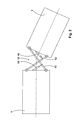
- the front end designated 1 is connected to the rear end 2 by the cross-like joint 10.
- This joint 10 comprises two articulated arms 11 and 12, which are each pivotally arranged on the front end and on the rear end.
- the articulated arms are arranged at the same distance from the central longitudinal axis of the vehicles on the vehicles or vehicle parts and are also of the same length.
- the position of the two articulated arms when the vehicle is cornering is shown in FIG. 2; it can be seen from this that the intersection of the two articulated arms moves outward in accordance with the curve to be traveled.
- the advantage of this joint is that the Align the rear car automatically in alignment with the front car after driving through the curve.
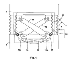
- Each articulated arm 11, 12 is assigned an attenuator 15, 16, this attenuator 15, 16 being connected to the one articulated arm and to the vehicle or vehicle part, that is to say the front end or rear end. This means that the movement of the joint is damped, and in particular when driving straight ahead it can also be provided that the dampers 15, 16 are stiff in order to keep the rear section stable relative to the front section.
- Each articulated arm 11, 12 shows a cam 11a, 12a in the region of the arrangement of the articulated arms on the rear carriage 2. This cam 11a, 12a pivots on the damping member 15, 16. This attenuator 15, 16 is attached to the vehicle.
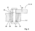
- the front or rear carriage 1, 2 shows a bearing pot 20 for attaching the articulated arm, which receives the bolt 21, the bolt in Storage pot is embedded by an elastomeric material 25.
- the bearing pot 20 opens here tapering in the direction of the articulated arm 11.
- the fixing of the bolt 21 in the bearing pot is such that the bearing arm can perform a movement in the direction of the arrow 30, as is required when such an articulated vehicle passes over or countersinks.
- a bore 27 is provided in the bottom of the bearing pot which is larger than the diameter of the bolt 21.
- an elastically flexible disc 29 is arranged in the bearing cup.
- the transition device comprising the double bellows 50 and the transition bridge 60 can also be seen from FIG. 4.
- the bridge 66 has an arcuate configuration 61 on its end facing the rear carriage 2.
Abstract
Description
- Die Erfindung betrifft ein Gelenk zwischen zwei gelenkig miteinander verbundenen Fahrzeugen oder Fahrzeugteilen eines Gelenkfahrzeuges, z. B. einen Gelenkbus oder ein Schienenfahrzeug.
- Gelenke zwischen zwei Fahrzeugen oder Fahrzeugteilen, beispielsweise bei einem Gelenkbus, sind hinreichend bekannt. Hierbei ist ein zentrales Gelenk in Form eines Knickgelenkes vorgesehen, mit einer in der Mittellängsachse des Fahrzeugs angeordneten zentralen Achse, wobei in diese Achse das Fahrzeug bei Kurvenfahrt einknickt. Nachteilig bei den bekannten Knickgelenken ist, dass aufgrund der Erstreckung des Gelenkes zwischen den beiden Fahrzeugen oder Fahrzeugteilen ein Abstand von etwa 1600 mm erforderlich ist. Da der Raum, den das Gelenk zwischen den beiden Fahrzeugen oder Fahrzeugteilen in Anspruch nimmt, vom Grundsatz her ein nur beschränkt nutzbarer Raum ist, besteht ein Interesse darin, diesen Raum und damit den Abstand zwischen den beiden Fahrzeugen oder Fahrzeugteilen zu minimieren, um gegebenenfalls eine weitere Sitzreihe in den Fahrzeugen oder Fahrzeugteilen unterbringen zu können.
- Der Erfindung liegt daher die Aufgabe zugrunde, ein Gelenk, insbesondere ein Knickgelenk, bereitzustellen, durch das der Abstand zwischen den beiden Fahrzeugen oder Fahrzeugteilen, die durch das Gelenk miteinander verbunden sind, gegenüber einem herkömmlichen Knickgelenk vermindert werden kann.
- Die Aufgabe wird erfindungsgemäß durch zwei kreuzweise und drehbar an den Fahrzeugen oder Fahrzeugteilen angelenkten Gelenkarme gelöst. Es hat sich herausgestellt, dass durch ein derart ausgebildetes Gelenk der Abstand zwischen den beiden Fahrzeugen oder Fahrzeugteilen von bislang ca. 1600 mm auf unter 1000 mm verkürzt werden kann. Dies ermöglicht die Anordnung einer weiteren Sitzreihe in einem der Fahrzeuge bzw. Fahrzeugteile. Vorteilhaft ist hierbei weiterhin, dass der Balg aufgrund des geringeren Abstandes zwischen den Fahrzeugen um etwa die Hälfte verkürzt werden kann, was preislich insofern insbesondere interessant, als der Mittelrahmen als stabilisierendes Element entfallen kann. Aufgrund der geringeren Länge kann auch der Balg, der Teil des Überganges zwischen zwei gelenkig miteinander verbundenen Fahrzeugen ist, kürzer ausgebildet sein. Wegen der geringeren Länge baucht der Balg bei Kurvenfahrt insbesondere auch nach unten weniger aus, so dass ein solches Gelenk sich insbesondere zum Einsatz in Niederflurfahrzeugen eignet.
- Weitere vorteilhafte Merkmale sind den Unteransprüchen zu entnehmen.
- So ist insbesondere vorgesehen, dass die Gelenkarme beabstandet zur Mittellängsachse des Fahrzeugs an den Fahrzeugen oder Fahrzeugteilen drehbar angeordnet sind, wobei vorteilhaft die Gelenkarme gleich lang sind. Aufgrund der Symmetrie des derartigen kreuzartig ausgebildeten Gelenkes wird ein weiterer Vorteil offenbart, der darin besteht, dass nach Durchfahren einer Kurve der Hinterwagen sich aufgrund der Gelenkgeometrie unmittelbar immer fluchtend zum Vorderwagen ausrichtet. Hierbei ist es völlig gleich, ob das Gelenkfahrzeug als Puscher ausgebildet ist, also als ein Fahrzeug, bei dem die hintere Achse angetrieben ist, oder als ein Fahrzeug, bei dem der Vorderwagen angetrieben ist. Dem gleichen Ziel dient die Maßnahme, die Gelenkarme jeweils im gleichen Abstand zur Mittellängsachse an dem Fahrzeug oder Fahrzeugteil anzuordnen.
- Nach einem weiteren Merkmal der Erfindung weist das Gelenk mindestens ein Dämpfungsglied auf, wobei nach einer Ausführungsform dieses Dämpfungsglied zwischen einem Gelenkarm und dem Fahrzeug oder Fahrzeugteil angeordnet sein kann. Die Dämpfung des Gelenkes ist erforderlich, um sicherzustellen, dass bei Geradeausfahrt der Hinterwagen gegenüber dem Vorderwagen stabil läuft.
- Im Einzelnen ist hierbei insbesondere vorgesehen, dass der Gelenkarm im Bereich der Anlenkung des Gelenkarms am Fahrzeug oder Fahrzeugteil einen Nocken aufweist, an dem das Dämpfungsglied angeordnet ist. Hierdurch wird die Möglichkeit eröffnet, kurze Dämpfungswege bei hoher Dämpfungskraft zu verwirklichen.
- Besonders platzsparend ist die Konstruktion dann, wenn der Nocken so an dem Gelenkarm angeordnet ist, dass das Dämpfungsglied, das zum Beispiel als Kolben-Zylindereinheit ausgebildet sein kann, parallel zur Querachse des Fahrzeugs oder Fahrzeugteils an diesem angeordnet ist, das heißt das Dämpfungsglied verläuft parallel zur Querachse des Fahrzeugs.
- Bekanntermaßen durchfahren Gelenkfahrzeuge Senken oder überfahren Kuppen. Das heißt, dass die Gelenkverbindung in der Lage sein muss, Nickbewegungen zwischen den Fahrzeugen bzw. Fahrzeugteilen nachgeben zu können. Insofern ist nach einem weiteren Merkmal der Erfindung vorgesehen, dass die drehgelenkige Anbindung der Gelenkarme an zumindest einem Fahrzeug oder Fahrzeugteil derart ist, dass die Fahrzeuge oder Fahrzeugteile relativ zueinander Nickbewegungen ausführen können. Hierzu ist im Einzelnen der Gelenkarm in vertikaler Richtung elastisch verschwenkbar an dem Fahrzeug oder Fahrzeugteil angeordnet ist, wobei vorzugsweise an dem einen Fahrzeug oder Fahrzeugteil ein Lagertopf vorgesehen ist, in dem ein Gelenkbolzen elastisch nachgiebig eingebettet ist, wobei der Gelenkbolzen an dem Gelenkarm angeordnet ist. Nach einem Merkmal ist hierbei vorgesehen, dass der Lagertopf in Richtung von dem Gelenkarm weg konisch zulaufend ausgebildet ist. Das bedeutet, dass bei Verschwenkung des Gelenkarmes in vertikaler Richtung, wie es auftritt, wenn ein derartiges Gelenkfahrzeug eine Kuppe oder eine Senke durchfährt, gegen die Kraft des in dem Topf angeordneten elastomeren Materials, z. B. Gummi, bewegt wird. Der maximale Nickwinkel ist hierbei naturgemäß abhängig von der Konizität des Lagertopfes bzw. auch von dem Material des Elastomers in dem Gelenktopf.
- Zwischen den beiden Fahrzeugen oder Fahrzeugteilen befindet sich eine Übergangseinrichtung umfassend mindestens einen Balg oder einen Doppelbalg mit einer Übergangsbrücke, um Personen ein Überwechseln zwischen den Fahrzeugen zu ermöglichen. Wesentlich ist die Ausgestaltung der Übergangsbrücke insofern, als diese an einem Ende kreisbogenförmig ausgebildet ist, um eine Drehbewegung der Fahrzeuge relativ zueinander zu erlauben.
- Anhand der Zeichnungen wird die Erfindung nachstehend beispielhaft näher erläutert:
- Fig. 1 zeigt schematisch den Vorderwagen und den Hinterwagen, die durch das erfindungsgemäße kreuzartige Gelenk miteinander verbunden sind in Geradeausfahrt;
- Fig. 2 zeigt die Darstellung gem. Fig. 1, wobei durch das Fahrzeug, bestehend aus Vorderwagen und Hinterwagen, eine Kurve durchfahren wird;
- Fig. 3 zeigt die Ausbildung des Lagertopfes für die Anordnung der Gelenkarme an den Fahrzeugen;
- Fig. 4 zeigt die Anordnung der Gelenkarme durch die beiden Dämpfungseinrichtungen im Detail in einer Variante.
- Der mit 1 bezeichnete Vorderwagen ist mit dem Hinterwagen 2 durch das kreuzartige Gelenk 10 verbunden. Dieses Gelenk 10 umfasst zwei Gelenkarme 11 und 12, die jeweils drehgelenkig an dem Vorderwagen und an dem Hinterwagen angeordnet sind. Hierbei sind die Gelenkarme in jeweils gleichem Abstand beabstandet zur Mittellängsachse der Fahrzeuge an den Fahrzeugen oder Fahrzeugteilen angeordnet und sind darüber hinaus gleichlang ausgebildet. Die Stellung der beiden Gelenkarme bei Kurvenfahrt des Fahrzeuges ergibt sich aus Fig. 2; so ist hieraus erkennbar, dass der Schnittpunkt der beiden Gelenkarme entsprechend der zu durchfahrenden Kurve nach außen wandert. Vorteilhaft bei diesem Gelenk ist, dass sich der Hinterwagen nach Durchfahren der Kurve unmittelbar fluchtend zum Vorderwagen selbsttätig ausrichtet.
- Jedem Gelenkarm 11, 12 ist jeweils ein Dämpfungsglied 15, 16 zugeordnet, wobei dieses Dämpfungsglied 15, 16 jeweils mit dem einen Gelenkarm und mit dem Fahrzeug bzw. Fahrzeugteil, sprich dem Vorderwagen bzw. Hinterwagen, verbunden ist. Das heißt, dass die Bewegung des Gelenkes gedämpft erfolgt, wobei bei Geradeausfahrt insbesondere auch vorgesehen sein kann, die Dämpfer 15, 16 steif auszugestalten, um den Hinterwagen relativ zum Vorderwagen stabil zu halten.
- Aus der Darstellung gemäß Fig. 4 ergibt sich im Einzelnen insbesondere die Anordnung der Dämpfungsglieder 15,16 einerseits am Fahrzeug bzw. Fahrzeugteil und am jeweiligen Gelenkarm in einer Variante. Jeder Gelenkarm 11,12 zeigt im Bereich der Anordnung der Gelenkarme am Hinterwagen 2 einen Nocken 11a, 12a. Dieser Nocken 11a, 12a nimmt schwenkbeweglich das Dämpfungsglied 15, 16 auf. Dieses Dämpfungsglied 15, 16 ist am Fahrzeug befestigt.
- Die gelenkige Anbindung der Arme am Vorder- bzw. am Hinterwagen ergibt sich im Einzelnen aus Fig. 3. So zeigt der Vorder- bzw. Hinterwagen 1, 2 zur Anbringung des Gelenkarmes einen Lagertopf 20, der den Bolzen 21 aufnimmt, wobei der Bolzen im Lagertopf durch ein Elastomermaterial 25 eingebettet ist. Der Lagertopf 20 öffnet sich hierbei in Richtung auf den Gelenkarm 11 konisch auslaufend. Die Fixierung des Bolzen 21 in dem Lagertopf ist hierbei derart, dass der Lagerarm eine Bewegung in Richtung des Pfeiles 30 ausführen kann, wie sie erforderlich ist, wenn ein derartiges Gelenkfahrzeug Kuppen über bzw. Senken durchfährt. Um eine derartige Bewegung zu ermöglichen, ist der Bolzen entsprechend gelenkig durch den Lagertopf aufgenommen, wobei hierzu im Boden des Lagertopfes eine Bohrung 27 vorgesehen, die größer ausgebildet ist, als der Durchmesser des Bolzens 21. Auch ist vorteilhaft zwischen dem Bolzenkopf 21a und dem Boden des Lagertopfes eine elastisch nachgiebige Scheibe 29 angeordnet.
- Aus der Fig. 4 ist ebenfalls die Übergangseinrichtung umfassend den Doppelbalg 50 und die Übergangsbrücke 60 erkennbar. Die Brücke 66 weist auf ihrem dem Hinterwagen 2 zugewandten Ende eine kreisbogenförmige Ausgestaltung 61 auf.
Claims (16)
- Gelenk zwischen zwei gelenkig miteinander verbundenen Fahrzeugen oder Fahrzeugteilen, z. B. einem Gelenkbus oder einem Schienenfahrzeug,
gekennzeichnet durch, zwei kreuzweise und drehbar an den Fahrzeugen (1, 2) angelenkten Gelenkarmen (11, 12). - Gelenk nach Anspruch 1,
dadurch gekennzeichnet, dass die Gelenkarme (11, 12) beabstandet zur Mittellängsachse des Fahrzeuges an den Fahrzeugen (1, 2) oder Fahrzeugteilen drehbar angeordnet sind. - Gelenk nach Anspruch 1,
dadurch gekennzeichnet, dass die Gelenkarme (11, 12) gleich lang sind. - Gelenk nach Anspruch 1,
dadurch gekennzeichnet, dass die Gelenkarme (11, 12) jeweils im gleichen Abstand zur Mittellängsachse an dem Fahrzeug (1, 2) oder Fahrzeugteil angeordnet sind. - Gelenk nach Anspruch 1,
dadurch gekennzeichnet, dass das Gelenk (10) mindestens ein Dämpfungsglied (15, 16) aufweist. - Gelenk nach Anspruch 5,
dadurch gekennzeichnet, dass das Dämpfungsglied (15, 16) einen Gelenkarm (11, 12) mit dem Fahrzeug oder Fahrzeugteil (1, 2) verbindet. - Gelenk nach Anspruch 5,
dadurch gekennzeichnet, dass der Gelenkarm (11, 12) im Bereich der Anlenkung des Gelenkarms am Fahrzeug oder Fahrzeugteil (1, 2) einen Nocken (11a, 12a) aufweist, an dem das Dämpfungsglied (15, 16) angeordnet ist. - Gelenk nach Anspruch 7,
dadurch gekennzeichnet, dass das Dämpfungsglied parallel zur Querachse des Fahrzeugs oder Fahrzeugteils (1, 2) an diesem angeordnet ist. - Gelenk nach Anspruch 8,
dadurch gekennzeichnet, dass das Dämpfungsglied als Kolbenzylindereinheit ausgebildet ist. - Gelenk nach Anspruch 1,
dadurch gekennzeichnet, dass das die drehgelenkige Anbindung der Gelenkarme (11, 12) an zumindestens einem Fahrzeug oder Fahrzeugteil (1, 2) derart ist, dass die Fahrzeuge oder Fahrzeugteile (1, 2) relativ zueinander Nickbewegungen ausführen können. - Gelenk nach Anspruch 1,
dadurch gekennzeichnet, dass der Gelenkarm (11, 12) in vertikaler Richtung elastisch verschwenkbar an dem Fahrzeug oder Fahrzeugteil (1, 2) angeordnet ist. - Gelenk nach Anspruch 11,
dadurch gekennzeichnet, dass an dem Fahrzeug oder Fahrzeugteil (11, 12) ein Lagertopf (20) vorgesehen ist, in dem ein Gelenkbolzen (21) elastisch nachgiebig eingebettet ist, wobei der Gelenkbolzen (21) an dem Gelenkarm (11, 12) angeordnet ist. - Gelenk nach Anspruch 12,
dadurch gekennzeichnet, dass der Lagertopf (20) in Richtung von dem Gelenkarm (11, 12) weg konisch zulaufend ausgebildet ist. - Gelenk nach Anspruch 1,
dadurch gekennzeichnet, dass zwischen den Fahrzeugen eine Übergangseinrichtung vorgesehen ist. - Gelenk nach Anspruch 14,
dadurch gekennzeichnet, dass die Übergangseinrichtung zumindest einen Balg und eine Übergangsbrücke umfasst. - Gelenk nach Anspruch 15,
dadurch gekennzeichnet, dass die Übergangsbrücke an einem Ende kreisbogenförmig ausgebildet ist.
Applications Claiming Priority (2)
| Application Number | Priority Date | Filing Date | Title |
|---|---|---|---|
| DE10209354A DE10209354A1 (de) | 2002-03-02 | 2002-03-02 | Gelenk zwischen zwei gelenkig miteinander verbundenen Fahrzeugen oder Fahrzeugteilen eines Gelenkfahrzeuges |
| DE10209354 | 2002-03-02 |
Publications (3)
| Publication Number | Publication Date |
|---|---|
| EP1342594A2 true EP1342594A2 (de) | 2003-09-10 |
| EP1342594A3 EP1342594A3 (de) | 2003-12-03 |
| EP1342594B1 EP1342594B1 (de) | 2006-06-07 |
Family
ID=27740614
Family Applications (1)
| Application Number | Title | Priority Date | Filing Date |
|---|---|---|---|
| EP03004504A Expired - Lifetime EP1342594B1 (de) | 2002-03-02 | 2003-02-28 | Gelenk zwischen zwei Teilen eines Gelenkfahrzeuges |
Country Status (6)
| Country | Link |
|---|---|
| EP (1) | EP1342594B1 (de) |
| CN (1) | CN1442323A (de) |
| AT (1) | ATE328749T1 (de) |
| DE (2) | DE10209354A1 (de) |
| ES (1) | ES2264500T3 (de) |
| PT (1) | PT1342594E (de) |
Cited By (9)
| Publication number | Priority date | Publication date | Assignee | Title |
|---|---|---|---|---|
| EP1531117A1 (de) * | 2003-11-15 | 2005-05-18 | HÜBNER GmbH | Zugfahrzeug mit einem insbesondere doppelachsigen Anhänger |
| EP1574365A1 (de) * | 2004-03-11 | 2005-09-14 | HÜBNER GmbH | Übergangsbrücke eines Übergangs zwischen zwei durch ein Gelenk miteinander verbundenen Fahrzeugen |
| WO2009148392A1 (en) * | 2008-06-05 | 2009-12-10 | Conspiro Aktiebolag | Connecting mechanism that connects two vehicles or vehicle parts and method for producing a link arm for a connecting mechanism |
| EP2366599A1 (de) * | 2010-03-18 | 2011-09-21 | Vossloh España S.A. | Schienenfahrzeug, insbesondere ein Niederflur-Schienenfahrzeug |
| DE102011106842A1 (de) * | 2011-07-07 | 2013-01-10 | A & A Logistik-Equipment GmbH & Co. KG | Routenzug |
| DE102014004681A1 (de) | 2014-04-01 | 2015-10-01 | A&A Logistik-Equipment GmbH & Co. KG | Fördermittelzug mit Schlingerunterdrückung |
| EP3034334A2 (de) | 2014-12-18 | 2016-06-22 | A&A Logistik-Equipment GmbH & Co. KG | Fördermittelzug mit kopplungskinematik |
| CN113443370A (zh) * | 2020-03-26 | 2021-09-28 | 德国邮政股份公司 | 铰接连接输送和/或分拣设备的两个元件的联接装置和对应的输送和/或分拣设备 |
| DE102021130750A1 (de) | 2021-11-24 | 2023-05-25 | Hupfer Metallwerke Gmbh & Co. Kg | Krankenhaustransportwagen und Krankenhauslogistiksystem |
Families Citing this family (8)
| Publication number | Priority date | Publication date | Assignee | Title |
|---|---|---|---|---|
| DE10238110A1 (de) * | 2002-08-21 | 2004-03-11 | Hübner GmbH | Balg zwischen zwei gelenkig miteinander verbundenen Fahrzeugen oder Fahrzeugteilen |
| DE202009013611U1 (de) | 2009-10-08 | 2011-02-24 | Hübner GmbH | Mindestens zwei Fahrzeugteile umfassendes Fahrzeug |
| DE202010016813U1 (de) | 2010-12-20 | 2012-03-26 | Liebherr-Aerospace Lindenberg Gmbh | Gelenk |
| DE202011100436U1 (de) | 2011-05-07 | 2011-06-21 | Hübner GmbH, 34123 | Straßengelenkfahrzeug |
| DE102012202838A1 (de) * | 2012-02-24 | 2013-08-29 | Bombardier Transportation Gmbh | Gelenk für Schienenfahrzeuge oder Schienenfahrzeugteile mit Winkelsensor |
| ES2543682T3 (es) * | 2013-02-09 | 2015-08-21 | HÜBNER GmbH & Co. KG | Dispositivo dispuesto en el sector de techo de dos componentes de vehículo unidos articuladamente para la limitación del movimiento de cabeceo relativo de los componentes de vehículo entre sí |
| DE102019104045A1 (de) * | 2019-02-17 | 2020-08-20 | A&A Logistik-Equipment GmbH & Co. KG | Routenzuganordnung oder Schleppverbund |
| CN113147812A (zh) * | 2020-01-07 | 2021-07-23 | 中国航天科工飞航技术研究院(中国航天海鹰机电技术研究院) | 具有上下双铰盘的车间连接结构及具有其的真空管道列车 |
Citations (9)
| Publication number | Priority date | Publication date | Assignee | Title |
|---|---|---|---|---|
| US2112559A (en) * | 1935-10-30 | 1938-03-29 | Davidson Isaac Forbes | Steering device for power propelled vehicles |
| US2603502A (en) * | 1946-07-16 | 1952-07-15 | Int Harvester Co | Short turning hitch |
| FR1397051A (fr) * | 1963-06-06 | 1965-04-23 | Pneuways Dev Company Private L | Perfectionnements aux véhicules à roues et aux bogies de ces véhicules |
| US4313616A (en) * | 1979-05-18 | 1982-02-02 | Howard D U | Speed responsive trailer stabilizer with zero slack |
| DE3134301A1 (de) * | 1981-08-29 | 1983-04-07 | M.A.N. Maschinenfabrik Augsburg-Nürnberg AG, 8000 München | Kupplungseinrichtung zwischen lastkraftwagen und anhaenger |
| EP0298401A1 (de) * | 1987-07-04 | 1989-01-11 | Roland Rief | Anhängervorrichtung, insbesondere für landwirtschaftliche Zugfahrzeuge |
| DE4329674A1 (de) * | 1993-09-02 | 1995-03-09 | Huebner Gummi & Kunststoff | Spaltausbildung zwischen der Übergangsplattform und den Fußböden von Vorder- und Hinterwagen von Gelenkfahrzeugen, insbesondere Straßengelenkomnibussen |
| US6283489B1 (en) * | 1999-09-27 | 2001-09-04 | Josef Thomas Hoog | Anti-sway control device for trailers |
| US20010052305A1 (en) * | 2000-05-22 | 2001-12-20 | Alstom | Rail vehicle including an end car extended by a cab |
Family Cites Families (8)
| Publication number | Priority date | Publication date | Assignee | Title |
|---|---|---|---|---|
| GB537092A (en) * | 1940-02-19 | 1941-06-09 | Frederick John Weakley | Improvements in or relating to coupling units for trailer vehicles |
| BE722156A (de) * | 1968-10-11 | 1969-03-14 | ||
| CS200687B1 (en) * | 1978-03-07 | 1980-09-15 | Ladislav Preslicka | Arrangement of the trailers for the transport of large weights notably of agriculcural machines |
| PL293749A1 (en) * | 1992-03-05 | 1993-09-06 | Wojciech Marian Pilarczyk | Coupling assembly of variable geometry in particular for trailer-truck units |
| DE4227126A1 (de) * | 1992-05-07 | 1993-11-11 | Huebner Gummi & Kunststoff | Gelenkverbindung zwischen zwei gelenkig miteinander verbundenen Fahrzeugen |
| US5775714A (en) * | 1996-03-15 | 1998-07-07 | Meadows; Leon | Tow bar |
| DE29803504U1 (de) * | 1998-02-28 | 1999-07-08 | Huebner Gummi & Kunststoff | Drehgelenk zwischen zwei Fahrzeugen oder Fahrzeugteilen |
| DE29822472U1 (de) * | 1998-12-18 | 1999-04-01 | Huebner Gummi & Kunststoff | Hydraulikanlage für die Dämpfung der Drehbewegung eines Drehgelenkes zwischen zwei Fahrzeugteilen eines Gelenkfahrzeuges, z.B. eines Gelenkbusses |
-
2002
- 2002-03-02 DE DE10209354A patent/DE10209354A1/de not_active Withdrawn
- 2002-10-15 CN CN02146232.1A patent/CN1442323A/zh active Pending
-
2003
- 2003-02-28 DE DE50303633T patent/DE50303633D1/de not_active Expired - Lifetime
- 2003-02-28 PT PT03004504T patent/PT1342594E/pt unknown
- 2003-02-28 ES ES03004504T patent/ES2264500T3/es not_active Expired - Lifetime
- 2003-02-28 EP EP03004504A patent/EP1342594B1/de not_active Expired - Lifetime
- 2003-02-28 AT AT03004504T patent/ATE328749T1/de active
Patent Citations (9)
| Publication number | Priority date | Publication date | Assignee | Title |
|---|---|---|---|---|
| US2112559A (en) * | 1935-10-30 | 1938-03-29 | Davidson Isaac Forbes | Steering device for power propelled vehicles |
| US2603502A (en) * | 1946-07-16 | 1952-07-15 | Int Harvester Co | Short turning hitch |
| FR1397051A (fr) * | 1963-06-06 | 1965-04-23 | Pneuways Dev Company Private L | Perfectionnements aux véhicules à roues et aux bogies de ces véhicules |
| US4313616A (en) * | 1979-05-18 | 1982-02-02 | Howard D U | Speed responsive trailer stabilizer with zero slack |
| DE3134301A1 (de) * | 1981-08-29 | 1983-04-07 | M.A.N. Maschinenfabrik Augsburg-Nürnberg AG, 8000 München | Kupplungseinrichtung zwischen lastkraftwagen und anhaenger |
| EP0298401A1 (de) * | 1987-07-04 | 1989-01-11 | Roland Rief | Anhängervorrichtung, insbesondere für landwirtschaftliche Zugfahrzeuge |
| DE4329674A1 (de) * | 1993-09-02 | 1995-03-09 | Huebner Gummi & Kunststoff | Spaltausbildung zwischen der Übergangsplattform und den Fußböden von Vorder- und Hinterwagen von Gelenkfahrzeugen, insbesondere Straßengelenkomnibussen |
| US6283489B1 (en) * | 1999-09-27 | 2001-09-04 | Josef Thomas Hoog | Anti-sway control device for trailers |
| US20010052305A1 (en) * | 2000-05-22 | 2001-12-20 | Alstom | Rail vehicle including an end car extended by a cab |
Cited By (13)
| Publication number | Priority date | Publication date | Assignee | Title |
|---|---|---|---|---|
| EP1531117A1 (de) * | 2003-11-15 | 2005-05-18 | HÜBNER GmbH | Zugfahrzeug mit einem insbesondere doppelachsigen Anhänger |
| EP1574365A1 (de) * | 2004-03-11 | 2005-09-14 | HÜBNER GmbH | Übergangsbrücke eines Übergangs zwischen zwei durch ein Gelenk miteinander verbundenen Fahrzeugen |
| CN100368215C (zh) * | 2004-03-11 | 2008-02-13 | 许布奈有限公司 | 两个相互铰接的车辆之间的带有折棚的过渡部的过桥 |
| US7338060B2 (en) | 2004-03-11 | 2008-03-04 | Hubner Gmbh | Corridor connection of a connection having a bellows between two vehicles connected together by a joint |
| WO2009148392A1 (en) * | 2008-06-05 | 2009-12-10 | Conspiro Aktiebolag | Connecting mechanism that connects two vehicles or vehicle parts and method for producing a link arm for a connecting mechanism |
| EP2366599A1 (de) * | 2010-03-18 | 2011-09-21 | Vossloh España S.A. | Schienenfahrzeug, insbesondere ein Niederflur-Schienenfahrzeug |
| DE102011106842A1 (de) * | 2011-07-07 | 2013-01-10 | A & A Logistik-Equipment GmbH & Co. KG | Routenzug |
| DE102014004681A1 (de) | 2014-04-01 | 2015-10-01 | A&A Logistik-Equipment GmbH & Co. KG | Fördermittelzug mit Schlingerunterdrückung |
| DE102014004681B4 (de) * | 2014-04-01 | 2017-08-10 | A&A Logistik-Equipment GmbH & Co. KG | Fördermittelzug mit Schlingerunterdrückung |
| EP3034334A2 (de) | 2014-12-18 | 2016-06-22 | A&A Logistik-Equipment GmbH & Co. KG | Fördermittelzug mit kopplungskinematik |
| DE102014018671A1 (de) | 2014-12-18 | 2016-06-23 | A&A Logistik-Equipment GmbH & Co. KG | Fördermittelzug mit Kopplungskinematik |
| CN113443370A (zh) * | 2020-03-26 | 2021-09-28 | 德国邮政股份公司 | 铰接连接输送和/或分拣设备的两个元件的联接装置和对应的输送和/或分拣设备 |
| DE102021130750A1 (de) | 2021-11-24 | 2023-05-25 | Hupfer Metallwerke Gmbh & Co. Kg | Krankenhaustransportwagen und Krankenhauslogistiksystem |
Also Published As
| Publication number | Publication date |
|---|---|
| DE10209354A1 (de) | 2003-09-25 |
| PT1342594E (pt) | 2006-08-31 |
| EP1342594B1 (de) | 2006-06-07 |
| ATE328749T1 (de) | 2006-06-15 |
| EP1342594A3 (de) | 2003-12-03 |
| CN1442323A (zh) | 2003-09-17 |
| ES2264500T3 (es) | 2007-01-01 |
| DE50303633D1 (de) | 2006-07-20 |
Similar Documents
| Publication | Publication Date | Title |
|---|---|---|
| EP1342594A2 (de) | Gelenk zwischen zwei Teilen eines Gelenkfahrzeuges | |
| EP1916181B1 (de) | Gelenk zwischen zwei gelenkig miteinander verbundenen Fahrzeugteilen, z. B. eines Gelenkfahrzeugs | |
| EP2429837B1 (de) | Fahrzeug-radaufhängung der schräglenker-bauart | |
| EP1712443B1 (de) | Mehrgliedriges Gelenkfahrzeug, insbesondere Schienenfahrzeug. | |
| DE102005037973A1 (de) | Einrichtung zur Verstellung des Radsturzes oder der Vorspur | |
| EP3028915B1 (de) | Im Dachbereich zwischen zwei gelenkig miteinander verbundener Fahrzeugteile angeordnetes Gelenk | |
| CH671195A5 (de) | ||
| EP0567950A1 (de) | Schienenfahrzeug | |
| EP1245468B1 (de) | Gelenk zwischen zwei Fahrzeugen oder Fahrzeugteilen (Stichwort: "Drehpendelgelenk") | |
| EP0420801B1 (de) | Schienenfahrzeug | |
| EP1574365A1 (de) | Übergangsbrücke eines Übergangs zwischen zwei durch ein Gelenk miteinander verbundenen Fahrzeugen | |
| WO2020151848A1 (de) | Kippentkoppelte lenkvorrichtung eines motorrades | |
| DE102007027592A1 (de) | Fahrzeug mit gelenkig verbundenen Wagenkästen | |
| EP1928722B1 (de) | Fahrzeug mit nickgelenk | |
| DE19611114B4 (de) | Radaufhängung einer ungelenkten Kraftfahrzeugachse | |
| EP1215164B1 (de) | Flurförderung mit einer federnd aufgehängten Antriebsachse | |
| DE1219812B (de) | Radaufhaengung fuer Kraftfahrzeuge | |
| EP0523210B1 (de) | Personenübergangseinrichtung von schienenfahrzeugen | |
| DE102008048178A1 (de) | Einzelradaufhängung für Kraftfahrzeug mit Sturzeinstellung | |
| DE102016111990B4 (de) | Lenkersystem | |
| DE4229992A1 (de) | Scheibenwischerantriebsanordnung | |
| DE3741144C2 (de) | ||
| DE3840660C2 (de) | ||
| DE8513611U1 (de) | Fahrzeuggelenkzug | |
| DE4314458C1 (de) | Weiche für einen Hängeförderer |
Legal Events
| Date | Code | Title | Description |
|---|---|---|---|
| PUAI | Public reference made under article 153(3) epc to a published international application that has entered the european phase |
Free format text: ORIGINAL CODE: 0009012 |
|
| AK | Designated contracting states |
Kind code of ref document: A2 Designated state(s): AT BE BG CH CY CZ DE DK EE ES FI FR GB GR HU IE IT LI LU MC NL PT SE SI SK TR |
|
| AX | Request for extension of the european patent |
Extension state: AL LT LV MK RO |
|
| 17P | Request for examination filed |
Effective date: 20030716 |
|
| PUAL | Search report despatched |
Free format text: ORIGINAL CODE: 0009013 |
|
| AK | Designated contracting states |
Kind code of ref document: A3 Designated state(s): AT BE BG CH CY CZ DE DK EE ES FI FR GB GR HU IE IT LI LU MC NL PT SE SI SK TR |
|
| AX | Request for extension of the european patent |
Extension state: AL LT LV MK RO |
|
| 17Q | First examination report despatched |
Effective date: 20040405 |
|
| AKX | Designation fees paid |
Designated state(s): AT BE BG CH CY CZ DE DK EE ES FI FR GB GR HU IE IT LI LU MC NL PT SE SI SK TR |
|
| GRAP | Despatch of communication of intention to grant a patent |
Free format text: ORIGINAL CODE: EPIDOSNIGR1 |
|
| GRAC | Information related to communication of intention to grant a patent modified |
Free format text: ORIGINAL CODE: EPIDOSCIGR1 |
|
| GRAS | Grant fee paid |
Free format text: ORIGINAL CODE: EPIDOSNIGR3 |
|
| GRAA | (expected) grant |
Free format text: ORIGINAL CODE: 0009210 |
|
| AK | Designated contracting states |
Kind code of ref document: B1 Designated state(s): AT BE BG CH CY CZ DE DK EE ES FI FR GB GR HU IE IT LI LU MC NL PT SE SI SK TR |
|
| PG25 | Lapsed in a contracting state [announced via postgrant information from national office to epo] |
Ref country code: IT Free format text: LAPSE BECAUSE OF FAILURE TO SUBMIT A TRANSLATION OF THE DESCRIPTION OR TO PAY THE FEE WITHIN THE PRESCRIBED TIME-LIMIT;WARNING: LAPSES OF ITALIAN PATENTS WITH EFFECTIVE DATE BEFORE 2007 MAY HAVE OCCURRED AT ANY TIME BEFORE 2007. THE CORRECT EFFECTIVE DATE MAY BE DIFFERENT FROM THE ONE RECORDED. Effective date: 20060607 Ref country code: SI Free format text: LAPSE BECAUSE OF FAILURE TO SUBMIT A TRANSLATION OF THE DESCRIPTION OR TO PAY THE FEE WITHIN THE PRESCRIBED TIME-LIMIT Effective date: 20060607 Ref country code: SK Free format text: LAPSE BECAUSE OF FAILURE TO SUBMIT A TRANSLATION OF THE DESCRIPTION OR TO PAY THE FEE WITHIN THE PRESCRIBED TIME-LIMIT Effective date: 20060607 Ref country code: FI Free format text: LAPSE BECAUSE OF FAILURE TO SUBMIT A TRANSLATION OF THE DESCRIPTION OR TO PAY THE FEE WITHIN THE PRESCRIBED TIME-LIMIT Effective date: 20060607 |
|
| REG | Reference to a national code |
Ref country code: GB Ref legal event code: FG4D Free format text: NOT ENGLISH Ref country code: SE Ref legal event code: TRGR |
|
| REG | Reference to a national code |
Ref country code: CH Ref legal event code: EP |
|
| GBT | Gb: translation of ep patent filed (gb section 77(6)(a)/1977) |
Effective date: 20060607 |
|
| REG | Reference to a national code |
Ref country code: CH Ref legal event code: NV Representative=s name: R. A. EGLI & CO. PATENTANWAELTE |
|
| REG | Reference to a national code |
Ref country code: IE Ref legal event code: FG4D Free format text: LANGUAGE OF EP DOCUMENT: GERMAN |
|
| REF | Corresponds to: |
Ref document number: 50303633 Country of ref document: DE Date of ref document: 20060720 Kind code of ref document: P |
|
| REG | Reference to a national code |
Ref country code: HU Ref legal event code: AG4A Ref document number: E000476 Country of ref document: HU |
|
| REG | Reference to a national code |
Ref country code: PT Ref legal event code: SC4A Effective date: 20060628 |
|
| PG25 | Lapsed in a contracting state [announced via postgrant information from national office to epo] |
Ref country code: DK Free format text: LAPSE BECAUSE OF FAILURE TO SUBMIT A TRANSLATION OF THE DESCRIPTION OR TO PAY THE FEE WITHIN THE PRESCRIBED TIME-LIMIT Effective date: 20060907 |
|
| REG | Reference to a national code |
Ref country code: GR Ref legal event code: EP Ref document number: 20060402588 Country of ref document: GR |
|
| ET | Fr: translation filed | ||
| REG | Reference to a national code |
Ref country code: ES Ref legal event code: FG2A Ref document number: 2264500 Country of ref document: ES Kind code of ref document: T3 |
|
| PG25 | Lapsed in a contracting state [announced via postgrant information from national office to epo] |
Ref country code: MC Free format text: LAPSE BECAUSE OF NON-PAYMENT OF DUE FEES Effective date: 20070228 |
|
| PLBE | No opposition filed within time limit |
Free format text: ORIGINAL CODE: 0009261 |
|
| STAA | Information on the status of an ep patent application or granted ep patent |
Free format text: STATUS: NO OPPOSITION FILED WITHIN TIME LIMIT |
|
| 26N | No opposition filed |
Effective date: 20070308 |
|
| PG25 | Lapsed in a contracting state [announced via postgrant information from national office to epo] |
Ref country code: BG Free format text: LAPSE BECAUSE OF FAILURE TO SUBMIT A TRANSLATION OF THE DESCRIPTION OR TO PAY THE FEE WITHIN THE PRESCRIBED TIME-LIMIT Effective date: 20060907 |
|
| PG25 | Lapsed in a contracting state [announced via postgrant information from national office to epo] |
Ref country code: EE Free format text: LAPSE BECAUSE OF FAILURE TO SUBMIT A TRANSLATION OF THE DESCRIPTION OR TO PAY THE FEE WITHIN THE PRESCRIBED TIME-LIMIT Effective date: 20060607 |
|
| PG25 | Lapsed in a contracting state [announced via postgrant information from national office to epo] |
Ref country code: LU Free format text: LAPSE BECAUSE OF NON-PAYMENT OF DUE FEES Effective date: 20070228 Ref country code: CY Free format text: LAPSE BECAUSE OF FAILURE TO SUBMIT A TRANSLATION OF THE DESCRIPTION OR TO PAY THE FEE WITHIN THE PRESCRIBED TIME-LIMIT Effective date: 20060607 |
|
| PGFP | Annual fee paid to national office [announced via postgrant information from national office to epo] |
Ref country code: IE Payment date: 20140221 Year of fee payment: 12 Ref country code: NL Payment date: 20140218 Year of fee payment: 12 Ref country code: CZ Payment date: 20140221 Year of fee payment: 12 |
|
| PGFP | Annual fee paid to national office [announced via postgrant information from national office to epo] |
Ref country code: GR Payment date: 20140218 Year of fee payment: 12 |
|
| PGFP | Annual fee paid to national office [announced via postgrant information from national office to epo] |
Ref country code: GB Payment date: 20140218 Year of fee payment: 12 Ref country code: PT Payment date: 20140224 Year of fee payment: 12 |
|
| REG | Reference to a national code |
Ref country code: NL Ref legal event code: V1 Effective date: 20150901 |
|
| REG | Reference to a national code |
Ref country code: PT Ref legal event code: MM4A Free format text: LAPSE DUE TO NON-PAYMENT OF FEES Effective date: 20150831 |
|
| PG25 | Lapsed in a contracting state [announced via postgrant information from national office to epo] |
Ref country code: NL Free format text: LAPSE BECAUSE OF NON-PAYMENT OF DUE FEES Effective date: 20150901 |
|
| GBPC | Gb: european patent ceased through non-payment of renewal fee |
Effective date: 20150228 |
|
| PG25 | Lapsed in a contracting state [announced via postgrant information from national office to epo] |
Ref country code: CZ Free format text: LAPSE BECAUSE OF NON-PAYMENT OF DUE FEES Effective date: 20150228 Ref country code: PT Free format text: LAPSE BECAUSE OF NON-PAYMENT OF DUE FEES Effective date: 20150831 |
|
| REG | Reference to a national code |
Ref country code: GR Ref legal event code: ML Ref document number: 20060402588 Country of ref document: GR Effective date: 20150902 |
|
| PG25 | Lapsed in a contracting state [announced via postgrant information from national office to epo] |
Ref country code: GR Free format text: LAPSE BECAUSE OF NON-PAYMENT OF DUE FEES Effective date: 20150902 |
|
| REG | Reference to a national code |
Ref country code: IE Ref legal event code: MM4A |
|
| PG25 | Lapsed in a contracting state [announced via postgrant information from national office to epo] |
Ref country code: GB Free format text: LAPSE BECAUSE OF NON-PAYMENT OF DUE FEES Effective date: 20150228 Ref country code: IE Free format text: LAPSE BECAUSE OF NON-PAYMENT OF DUE FEES Effective date: 20150228 |
|
| REG | Reference to a national code |
Ref country code: FR Ref legal event code: PLFP Year of fee payment: 14 |
|
| REG | Reference to a national code |
Ref country code: FR Ref legal event code: PLFP Year of fee payment: 15 |
|
| REG | Reference to a national code |
Ref country code: FR Ref legal event code: PLFP Year of fee payment: 16 |
|
| PGFP | Annual fee paid to national office [announced via postgrant information from national office to epo] |
Ref country code: CH Payment date: 20180221 Year of fee payment: 16 |
|
| PGFP | Annual fee paid to national office [announced via postgrant information from national office to epo] |
Ref country code: AT Payment date: 20180220 Year of fee payment: 16 Ref country code: BE Payment date: 20180221 Year of fee payment: 16 Ref country code: TR Payment date: 20180227 Year of fee payment: 16 |
|
| PGFP | Annual fee paid to national office [announced via postgrant information from national office to epo] |
Ref country code: DE Payment date: 20190219 Year of fee payment: 17 Ref country code: ES Payment date: 20190319 Year of fee payment: 17 Ref country code: IT Payment date: 20190222 Year of fee payment: 17 |
|
| PGFP | Annual fee paid to national office [announced via postgrant information from national office to epo] |
Ref country code: HU Payment date: 20190215 Year of fee payment: 17 Ref country code: SE Payment date: 20190221 Year of fee payment: 17 Ref country code: FR Payment date: 20190221 Year of fee payment: 17 |
|
| REG | Reference to a national code |
Ref country code: CH Ref legal event code: PL |
|
| REG | Reference to a national code |
Ref country code: AT Ref legal event code: MM01 Ref document number: 328749 Country of ref document: AT Kind code of ref document: T Effective date: 20190228 |
|
| REG | Reference to a national code |
Ref country code: BE Ref legal event code: MM Effective date: 20190228 |
|
| PG25 | Lapsed in a contracting state [announced via postgrant information from national office to epo] |
Ref country code: CH Free format text: LAPSE BECAUSE OF NON-PAYMENT OF DUE FEES Effective date: 20190228 Ref country code: LI Free format text: LAPSE BECAUSE OF NON-PAYMENT OF DUE FEES Effective date: 20190228 Ref country code: AT Free format text: LAPSE BECAUSE OF NON-PAYMENT OF DUE FEES Effective date: 20190228 |
|
| PG25 | Lapsed in a contracting state [announced via postgrant information from national office to epo] |
Ref country code: BE Free format text: LAPSE BECAUSE OF NON-PAYMENT OF DUE FEES Effective date: 20190228 |
|
| REG | Reference to a national code |
Ref country code: DE Ref legal event code: R119 Ref document number: 50303633 Country of ref document: DE |
|
| PG25 | Lapsed in a contracting state [announced via postgrant information from national office to epo] |
Ref country code: HU Free format text: LAPSE BECAUSE OF NON-PAYMENT OF DUE FEES Effective date: 20200301 |
|
| PG25 | Lapsed in a contracting state [announced via postgrant information from national office to epo] |
Ref country code: DE Free format text: LAPSE BECAUSE OF NON-PAYMENT OF DUE FEES Effective date: 20200901 Ref country code: FR Free format text: LAPSE BECAUSE OF NON-PAYMENT OF DUE FEES Effective date: 20200229 Ref country code: SE Free format text: LAPSE BECAUSE OF NON-PAYMENT OF DUE FEES Effective date: 20200229 |
|
| REG | Reference to a national code |
Ref country code: ES Ref legal event code: FD2A Effective date: 20210707 |
|
| PG25 | Lapsed in a contracting state [announced via postgrant information from national office to epo] |
Ref country code: IT Free format text: LAPSE BECAUSE OF NON-PAYMENT OF DUE FEES Effective date: 20200228 |
|
| PG25 | Lapsed in a contracting state [announced via postgrant information from national office to epo] |
Ref country code: ES Free format text: LAPSE BECAUSE OF NON-PAYMENT OF DUE FEES Effective date: 20200301 |
|
| PG25 | Lapsed in a contracting state [announced via postgrant information from national office to epo] |
Ref country code: TR Free format text: LAPSE BECAUSE OF NON-PAYMENT OF DUE FEES Effective date: 20190228 |