EP1340725B1 - Herstellungsverfahren einer photonischen Kristallfaser - Google Patents
Herstellungsverfahren einer photonischen Kristallfaser Download PDFInfo
- Publication number
- EP1340725B1 EP1340725B1 EP03009883A EP03009883A EP1340725B1 EP 1340725 B1 EP1340725 B1 EP 1340725B1 EP 03009883 A EP03009883 A EP 03009883A EP 03009883 A EP03009883 A EP 03009883A EP 1340725 B1 EP1340725 B1 EP 1340725B1
- Authority
- EP
- European Patent Office
- Prior art keywords
- fibre
- canes
- holes
- tube
- pressure
- Prior art date
- Legal status (The legal status is an assumption and is not a legal conclusion. Google has not performed a legal analysis and makes no representation as to the accuracy of the status listed.)
- Expired - Lifetime
Links
- 239000000835 fiber Substances 0.000 title claims abstract description 150
- 239000004038 photonic crystal Substances 0.000 title claims abstract description 39
- 238000000034 method Methods 0.000 title claims description 35
- 230000008569 process Effects 0.000 claims description 11
- 238000004891 communication Methods 0.000 claims description 2
- 239000012530 fluid Substances 0.000 claims description 2
- 239000002184 metal Substances 0.000 claims description 2
- 239000013590 bulk material Substances 0.000 abstract description 10
- 238000005253 cladding Methods 0.000 description 19
- 239000000463 material Substances 0.000 description 15
- VYPSYNLAJGMNEJ-UHFFFAOYSA-N Silicium dioxide Chemical compound O=[Si]=O VYPSYNLAJGMNEJ-UHFFFAOYSA-N 0.000 description 12
- 238000010586 diagram Methods 0.000 description 10
- 230000007547 defect Effects 0.000 description 9
- 230000000694 effects Effects 0.000 description 9
- 239000007787 solid Substances 0.000 description 7
- 229910001369 Brass Inorganic materials 0.000 description 5
- 239000010951 brass Substances 0.000 description 5
- 230000000737 periodic effect Effects 0.000 description 5
- 239000000377 silicon dioxide Substances 0.000 description 5
- 230000003287 optical effect Effects 0.000 description 4
- 230000001902 propagating effect Effects 0.000 description 4
- 238000004519 manufacturing process Methods 0.000 description 3
- 238000010009 beating Methods 0.000 description 2
- 230000008859 change Effects 0.000 description 2
- 238000013461 design Methods 0.000 description 2
- 239000011521 glass Substances 0.000 description 2
- 239000011159 matrix material Substances 0.000 description 2
- 230000007246 mechanism Effects 0.000 description 2
- 230000004048 modification Effects 0.000 description 2
- 238000012986 modification Methods 0.000 description 2
- 239000013307 optical fiber Substances 0.000 description 2
- 239000012780 transparent material Substances 0.000 description 2
- 239000005388 borosilicate glass Substances 0.000 description 1
- 239000013078 crystal Substances 0.000 description 1
- 238000003754 machining Methods 0.000 description 1
- 230000000877 morphologic effect Effects 0.000 description 1
- 230000009467 reduction Effects 0.000 description 1
- 238000007789 sealing Methods 0.000 description 1
- 238000001356 surgical procedure Methods 0.000 description 1
- 238000012546 transfer Methods 0.000 description 1
- 238000003466 welding Methods 0.000 description 1
Images


Classifications
-
- G—PHYSICS
- G02—OPTICS
- G02B—OPTICAL ELEMENTS, SYSTEMS OR APPARATUS
- G02B6/00—Light guides; Structural details of arrangements comprising light guides and other optical elements, e.g. couplings
- G02B6/02—Optical fibres with cladding with or without a coating
- G02B6/02295—Microstructured optical fibre
- G02B6/02314—Plurality of longitudinal structures extending along optical fibre axis, e.g. holes
- G02B6/02342—Plurality of longitudinal structures extending along optical fibre axis, e.g. holes characterised by cladding features, i.e. light confining region
- G02B6/02347—Longitudinal structures arranged to form a regular periodic lattice, e.g. triangular, square, honeycomb unit cell repeated throughout cladding
-
- G—PHYSICS
- G02—OPTICS
- G02B—OPTICAL ELEMENTS, SYSTEMS OR APPARATUS
- G02B6/00—Light guides; Structural details of arrangements comprising light guides and other optical elements, e.g. couplings
- G02B6/10—Light guides; Structural details of arrangements comprising light guides and other optical elements, e.g. couplings of the optical waveguide type
- G02B6/12—Light guides; Structural details of arrangements comprising light guides and other optical elements, e.g. couplings of the optical waveguide type of the integrated circuit kind
-
- B—PERFORMING OPERATIONS; TRANSPORTING
- B82—NANOTECHNOLOGY
- B82Y—SPECIFIC USES OR APPLICATIONS OF NANOSTRUCTURES; MEASUREMENT OR ANALYSIS OF NANOSTRUCTURES; MANUFACTURE OR TREATMENT OF NANOSTRUCTURES
- B82Y20/00—Nanooptics, e.g. quantum optics or photonic crystals
-
- C—CHEMISTRY; METALLURGY
- C03—GLASS; MINERAL OR SLAG WOOL
- C03B—MANUFACTURE, SHAPING, OR SUPPLEMENTARY PROCESSES
- C03B37/00—Manufacture or treatment of flakes, fibres, or filaments from softened glass, minerals, or slags
- C03B37/01—Manufacture of glass fibres or filaments
- C03B37/012—Manufacture of preforms for drawing fibres or filaments
- C03B37/01205—Manufacture of preforms for drawing fibres or filaments starting from tubes, rods, fibres or filaments
- C03B37/01211—Manufacture of preforms for drawing fibres or filaments starting from tubes, rods, fibres or filaments by inserting one or more rods or tubes into a tube
- C03B37/01217—Manufacture of preforms for drawing fibres or filaments starting from tubes, rods, fibres or filaments by inserting one or more rods or tubes into a tube for making preforms of polarisation-maintaining optical fibres
-
- C—CHEMISTRY; METALLURGY
- C03—GLASS; MINERAL OR SLAG WOOL
- C03B—MANUFACTURE, SHAPING, OR SUPPLEMENTARY PROCESSES
- C03B37/00—Manufacture or treatment of flakes, fibres, or filaments from softened glass, minerals, or slags
- C03B37/01—Manufacture of glass fibres or filaments
- C03B37/012—Manufacture of preforms for drawing fibres or filaments
- C03B37/01205—Manufacture of preforms for drawing fibres or filaments starting from tubes, rods, fibres or filaments
- C03B37/01211—Manufacture of preforms for drawing fibres or filaments starting from tubes, rods, fibres or filaments by inserting one or more rods or tubes into a tube
- C03B37/0122—Manufacture of preforms for drawing fibres or filaments starting from tubes, rods, fibres or filaments by inserting one or more rods or tubes into a tube for making preforms of photonic crystal, microstructured or holey optical fibres
-
- C—CHEMISTRY; METALLURGY
- C03—GLASS; MINERAL OR SLAG WOOL
- C03B—MANUFACTURE, SHAPING, OR SUPPLEMENTARY PROCESSES
- C03B37/00—Manufacture or treatment of flakes, fibres, or filaments from softened glass, minerals, or slags
- C03B37/01—Manufacture of glass fibres or filaments
- C03B37/02—Manufacture of glass fibres or filaments by drawing or extruding, e.g. direct drawing of molten glass from nozzles; Cooling fins therefor
- C03B37/025—Manufacture of glass fibres or filaments by drawing or extruding, e.g. direct drawing of molten glass from nozzles; Cooling fins therefor from reheated softened tubes, rods, fibres or filaments, e.g. drawing fibres from preforms
- C03B37/027—Fibres composed of different sorts of glass, e.g. glass optical fibres
- C03B37/02709—Polarisation maintaining fibres, e.g. PM, PANDA, bi-refringent optical fibres
-
- C—CHEMISTRY; METALLURGY
- C03—GLASS; MINERAL OR SLAG WOOL
- C03B—MANUFACTURE, SHAPING, OR SUPPLEMENTARY PROCESSES
- C03B37/00—Manufacture or treatment of flakes, fibres, or filaments from softened glass, minerals, or slags
- C03B37/01—Manufacture of glass fibres or filaments
- C03B37/02—Manufacture of glass fibres or filaments by drawing or extruding, e.g. direct drawing of molten glass from nozzles; Cooling fins therefor
- C03B37/025—Manufacture of glass fibres or filaments by drawing or extruding, e.g. direct drawing of molten glass from nozzles; Cooling fins therefor from reheated softened tubes, rods, fibres or filaments, e.g. drawing fibres from preforms
- C03B37/027—Fibres composed of different sorts of glass, e.g. glass optical fibres
- C03B37/02781—Hollow fibres, e.g. holey fibres
-
- C—CHEMISTRY; METALLURGY
- C03—GLASS; MINERAL OR SLAG WOOL
- C03B—MANUFACTURE, SHAPING, OR SUPPLEMENTARY PROCESSES
- C03B37/00—Manufacture or treatment of flakes, fibres, or filaments from softened glass, minerals, or slags
- C03B37/075—Manufacture of non-optical fibres or filaments consisting of different sorts of glass or characterised by shape, e.g. undulated fibres
- C03B37/0756—Hollow fibres
-
- G—PHYSICS
- G02—OPTICS
- G02B—OPTICAL ELEMENTS, SYSTEMS OR APPARATUS
- G02B6/00—Light guides; Structural details of arrangements comprising light guides and other optical elements, e.g. couplings
- G02B6/02—Optical fibres with cladding with or without a coating
- G02B6/02295—Microstructured optical fibre
- G02B6/02314—Plurality of longitudinal structures extending along optical fibre axis, e.g. holes
- G02B6/02342—Plurality of longitudinal structures extending along optical fibre axis, e.g. holes characterised by cladding features, i.e. light confining region
- G02B6/02347—Longitudinal structures arranged to form a regular periodic lattice, e.g. triangular, square, honeycomb unit cell repeated throughout cladding
- G02B6/02352—Complex periodic lattices or multiple interpenetrating periodic lattices, e.g. unit cell having more than two materials, partially internally coated holes, for multiple bandgaps
-
- G—PHYSICS
- G02—OPTICS
- G02B—OPTICAL ELEMENTS, SYSTEMS OR APPARATUS
- G02B6/00—Light guides; Structural details of arrangements comprising light guides and other optical elements, e.g. couplings
- G02B6/02—Optical fibres with cladding with or without a coating
- G02B6/02295—Microstructured optical fibre
- G02B6/02314—Plurality of longitudinal structures extending along optical fibre axis, e.g. holes
- G02B6/02342—Plurality of longitudinal structures extending along optical fibre axis, e.g. holes characterised by cladding features, i.e. light confining region
- G02B6/02357—Property of longitudinal structures or background material varies radially and/or azimuthally in the cladding, e.g. size, spacing, periodicity, shape, refractive index, graded index, quasiperiodic, quasicrystals
-
- G—PHYSICS
- G02—OPTICS
- G02B—OPTICAL ELEMENTS, SYSTEMS OR APPARATUS
- G02B6/00—Light guides; Structural details of arrangements comprising light guides and other optical elements, e.g. couplings
- G02B6/02—Optical fibres with cladding with or without a coating
- G02B6/02295—Microstructured optical fibre
- G02B6/02314—Plurality of longitudinal structures extending along optical fibre axis, e.g. holes
- G02B6/02342—Plurality of longitudinal structures extending along optical fibre axis, e.g. holes characterised by cladding features, i.e. light confining region
- G02B6/02361—Longitudinal structures forming multiple layers around the core, e.g. arranged in multiple rings with each ring having longitudinal elements at substantially the same radial distance from the core, having rotational symmetry about the fibre axis
-
- G—PHYSICS
- G02—OPTICS
- G02B—OPTICAL ELEMENTS, SYSTEMS OR APPARATUS
- G02B6/00—Light guides; Structural details of arrangements comprising light guides and other optical elements, e.g. couplings
- G02B6/02—Optical fibres with cladding with or without a coating
- G02B6/02295—Microstructured optical fibre
- G02B6/02314—Plurality of longitudinal structures extending along optical fibre axis, e.g. holes
- G02B6/02342—Plurality of longitudinal structures extending along optical fibre axis, e.g. holes characterised by cladding features, i.e. light confining region
- G02B6/02371—Cross section of longitudinal structures is non-circular
-
- G—PHYSICS
- G02—OPTICS
- G02B—OPTICAL ELEMENTS, SYSTEMS OR APPARATUS
- G02B6/00—Light guides; Structural details of arrangements comprising light guides and other optical elements, e.g. couplings
- G02B6/02—Optical fibres with cladding with or without a coating
- G02B6/02295—Microstructured optical fibre
- G02B6/02314—Plurality of longitudinal structures extending along optical fibre axis, e.g. holes
- G02B6/02342—Plurality of longitudinal structures extending along optical fibre axis, e.g. holes characterised by cladding features, i.e. light confining region
- G02B6/0238—Longitudinal structures having higher refractive index than background material, e.g. high index solid rods
-
- G—PHYSICS
- G02—OPTICS
- G02B—OPTICAL ELEMENTS, SYSTEMS OR APPARATUS
- G02B6/00—Light guides; Structural details of arrangements comprising light guides and other optical elements, e.g. couplings
- G02B6/10—Light guides; Structural details of arrangements comprising light guides and other optical elements, e.g. couplings of the optical waveguide type
- G02B6/105—Light guides; Structural details of arrangements comprising light guides and other optical elements, e.g. couplings of the optical waveguide type having optical polarisation effects
-
- G—PHYSICS
- G02—OPTICS
- G02B—OPTICAL ELEMENTS, SYSTEMS OR APPARATUS
- G02B6/00—Light guides; Structural details of arrangements comprising light guides and other optical elements, e.g. couplings
- G02B6/10—Light guides; Structural details of arrangements comprising light guides and other optical elements, e.g. couplings of the optical waveguide type
- G02B6/12—Light guides; Structural details of arrangements comprising light guides and other optical elements, e.g. couplings of the optical waveguide type of the integrated circuit kind
- G02B6/122—Basic optical elements, e.g. light-guiding paths
- G02B6/1225—Basic optical elements, e.g. light-guiding paths comprising photonic band-gap structures or photonic lattices
-
- G—PHYSICS
- G02—OPTICS
- G02B—OPTICAL ELEMENTS, SYSTEMS OR APPARATUS
- G02B6/00—Light guides; Structural details of arrangements comprising light guides and other optical elements, e.g. couplings
- G02B6/24—Coupling light guides
- G02B6/255—Splicing of light guides, e.g. by fusion or bonding
- G02B6/2551—Splicing of light guides, e.g. by fusion or bonding using thermal methods, e.g. fusion welding by arc discharge, laser beam, plasma torch
-
- G—PHYSICS
- G02—OPTICS
- G02B—OPTICAL ELEMENTS, SYSTEMS OR APPARATUS
- G02B6/00—Light guides; Structural details of arrangements comprising light guides and other optical elements, e.g. couplings
- G02B6/24—Coupling light guides
- G02B6/255—Splicing of light guides, e.g. by fusion or bonding
- G02B6/2552—Splicing of light guides, e.g. by fusion or bonding reshaping or reforming of light guides for coupling using thermal heating, e.g. tapering, forming of a lens on light guide ends
-
- G—PHYSICS
- G02—OPTICS
- G02B—OPTICAL ELEMENTS, SYSTEMS OR APPARATUS
- G02B6/00—Light guides; Structural details of arrangements comprising light guides and other optical elements, e.g. couplings
- G02B6/24—Coupling light guides
- G02B6/26—Optical coupling means
- G02B6/28—Optical coupling means having data bus means, i.e. plural waveguides interconnected and providing an inherently bidirectional system by mixing and splitting signals
- G02B6/2804—Optical coupling means having data bus means, i.e. plural waveguides interconnected and providing an inherently bidirectional system by mixing and splitting signals forming multipart couplers without wavelength selective elements, e.g. "T" couplers, star couplers
- G02B6/2821—Optical coupling means having data bus means, i.e. plural waveguides interconnected and providing an inherently bidirectional system by mixing and splitting signals forming multipart couplers without wavelength selective elements, e.g. "T" couplers, star couplers using lateral coupling between contiguous fibres to split or combine optical signals
- G02B6/2835—Optical coupling means having data bus means, i.e. plural waveguides interconnected and providing an inherently bidirectional system by mixing and splitting signals forming multipart couplers without wavelength selective elements, e.g. "T" couplers, star couplers using lateral coupling between contiguous fibres to split or combine optical signals formed or shaped by thermal treatment, e.g. couplers
-
- C—CHEMISTRY; METALLURGY
- C03—GLASS; MINERAL OR SLAG WOOL
- C03B—MANUFACTURE, SHAPING, OR SUPPLEMENTARY PROCESSES
- C03B2203/00—Fibre product details, e.g. structure, shape
- C03B2203/10—Internal structure or shape details
- C03B2203/14—Non-solid, i.e. hollow products, e.g. hollow clad or with core-clad interface
-
- C—CHEMISTRY; METALLURGY
- C03—GLASS; MINERAL OR SLAG WOOL
- C03B—MANUFACTURE, SHAPING, OR SUPPLEMENTARY PROCESSES
- C03B2203/00—Fibre product details, e.g. structure, shape
- C03B2203/30—Polarisation maintaining [PM], i.e. birefringent products, e.g. with elliptical core, by use of stress rods, "PANDA" type fibres
-
- C—CHEMISTRY; METALLURGY
- C03—GLASS; MINERAL OR SLAG WOOL
- C03B—MANUFACTURE, SHAPING, OR SUPPLEMENTARY PROCESSES
- C03B2203/00—Fibre product details, e.g. structure, shape
- C03B2203/42—Photonic crystal fibres, e.g. fibres using the photonic bandgap PBG effect, microstructured or holey optical fibres
-
- C—CHEMISTRY; METALLURGY
- C03—GLASS; MINERAL OR SLAG WOOL
- C03B—MANUFACTURE, SHAPING, OR SUPPLEMENTARY PROCESSES
- C03B2205/00—Fibre drawing or extruding details
- C03B2205/08—Sub-atmospheric pressure applied, e.g. vacuum
-
- C—CHEMISTRY; METALLURGY
- C03—GLASS; MINERAL OR SLAG WOOL
- C03B—MANUFACTURE, SHAPING, OR SUPPLEMENTARY PROCESSES
- C03B2205/00—Fibre drawing or extruding details
- C03B2205/10—Fibre drawing or extruding details pressurised
Definitions
- This invention relates to photonic crystal fibres and to a method of producing photonic crystal fibres.
- a photonic crystal fibre is a special form of optical fibre.
- Optical fibres are used in many fields including telecommunications, laser machining and welding, laser beam and power delivery, fibre lasers, sensors and medical diagnostics and surgery. They are typically made entirely from solid transparent materials such as glass and each fibre typically has the same cross-sectional structure along its length. The transparent material in one part (usually the middle) of the cross-section has a higher refractive index than the rest and forms an optical core within which light is guided by total internal reflection. We refer to such a fibre as a standard fibre.
- Single-mode optical fibres are preferred for many applications because of their superior wave-guiding properties. However, even so-called single-mode optical fibres do not generally offer adequate control over the polarisation of propagating light.
- a single-mode fibre is so called because it supports only one transverse spatial mode at a frequency of interest, but that spatial mode exists in two polarisation states; that is two degenerate modes that are polarised in orthogonal directions.
- imperfections will break the degeneracy of those modes and modal birefringence will occur; that is, the mode propagation constant ⁇ will be slightly different for each of the orthogonal modes. Because the modal birefringence results from random imperfections, the propagation constants will vary randomly along the fibre.
- light introduced into the fibre will propagate in both modes and will be coupled from one to the other by small bends and twists in the fibre. Linearly polarised light will be scrambled into an arbitrary polarisation state as it propagates along the fibre.
- birefringence can be deliberately introduced into the fibre (so that the effective indices of the two polarisation modes are different) in order to render insignificant the effects of small imperfections. If light is linearly polarised in a direction parallel to one of the optic axes of the fibre then the light will maintain its polarisation.
- the shorter the beat length the more resilient is the fibre to polarisation-scrambling effects.
- conventional polarisation-preserving fibre has a beat length of the order of a millimetre.
- k 0
- k 0 2 ⁇ ⁇ (where ⁇ is the wavelength) and n x and n y are the refractive indices seen by the orthogonal modes.
- the photonic-crystal fibre typically, this is made from a single solid, and substantially transparent, material within which is embedded a periodic array of air holes, running parallel to the fibre axis and extending the full length of the fibre.
- a defect in the form of a single missing air hole within the regular array forms a region of raised refractive index within which light is guided, in a manner analogous to total-internal-reflection guiding in standard fibres.
- Another mechanism for guiding light is based on photonic-band-gap effects rather than total internal reflection. Photonic-band-gap guidance can be obtained by suitable design of the array of air holes. Light with particular propagation constants can be confined to the core and will propagate therein.
- Photonic-crystal fibre can be fabricated by stacking glass canes, some of which are capillaries on a macroscopic scale, into the required shape, and then holding them in place while fusing them together and drawing them down into a fibre.
- PCF has unusual properties such as the ability to guide light in a single-mode over a very broad range of wavelengths, and to guide light having a relatively large mode area which remains single-mode.
- Birefringence can be produced by several mechanisms. It can be caused by the anisotropic nature of the polarisability of a material; i.e. by anisotropy at an atomic level. It can be caused by the arrangement of elements of a material structure at a scale larger than atomic; that phenomenon is known as form birefringence. It can also be caused by mechanical stress; that phenomenon is known as stress birefringence or the photo-elastic effect. In standard fibres, form birefringence is achieved by changing the shape of the fibre cross-section; for example, by making the core or cladding elliptical. Birefringence in a weakly-guiding fibre is generally rather weak (B ⁇ 10 -6 ).
- the birefringence is such that light with a wavelength of 1.5 microns propagating in the fibre has a beat length of less than 1 cm. More advantageously, the birefringence is such that light with a wavelength of 1.5 microns propagating in the fibre has a beat length of less than 5 mm. More advantageously, the birefringence is such that light with a wavelength of 1.5 microns propagating in the fibre has a beat length of less than 1 mm and preferably less than 0.5 mm; such short beat lengths are not generally obtainable in standard fibres.
- a particular fibre may not guide light at a wavelength of 1.5 microns; in that case, the beat length at a guided wavelength may be readily scaled up or down to an equivalent beat length at 1.5 microns.
- a beat length of 1mm at a wavelength of 1.55 microns is equivalent to a beat length of 0.41mm at a wavelength of 633nm
- a beat length of 0.5mm at a wavelength of 1.55 microns is equivalent to a beat length of 0.21mm at a wavelength of 633nm.
- the lack of symmetry may arise in some feature of the internal microstructure of the fibre and, commonly, of the arrangement of holes, whilst the overall cross-sectional shape of the fibre may be circular and thus have circular symmetry; it is within the scope of the invention for the arrangement of holes to have more-than-two-fold rotational symmetry but for the fibre to lack more-than-two-fold rotational symmetry in some other sense and examples of such arrangements are given below.
- the rotational symmetry is about an axis passing through the core.
- linearly polarised light would have the same propagation constant ⁇ when polarised parallel to two or more (not necessarily orthogonal) axes.
- imperfections in the fibre will result in power transfer between modes polarised parallel to each of those axes. Consequently, light which is initially linearly polarised will excite additional modes and quickly become randomly polarised.
- the core may include a hole.
- the hole may be filled with material other than air.
- the core may not include a hole.
- the arrangement of holes may have at-most-two-fold rotational symmetry parallel to the longitudinal axis of the fibre.
- the arrangement of holes may have higher-than-two-fold rotational symmetry about an axis parallel to the longitudinal axis of the fibre.
- the rotational symmetry may be about an axis passing through the core.
- the lack of higher rotational symmetry may at least partly result from a variation, across the cross-section of the fibre, in one or more of the following: the microstructure of the core, the diameter of the holes, the bulk material, the material contained in the holes or the shape of the holes.
- the shape variation may be due to deformation resulting from stresses in the fibre as it is drawn.
- the lack of higher rotational symmetry may result from a variation across the cross-section of the fibre, in one of the following in combination with one or more of the following or with a variation in another parameter: the microstructure of the core, the diameter of the holes, the bulk material, the material contained in the holes, the shape of the holes.
- the method comprises the following steps:
- birefringence can be introduced by including in the preform different capillaries at two-fold symmetric pairs of lattice sites. Those inclusions might be placed near to the core so as to alter the shape of the guided mode (“form birefringence") or they might be placed some way from the core but be made of a material with different properties, thus altering the pattern of stresses within the fibre core (“stress birefringence").
- the preform may be structured so as to introduce birefringence by forming substantial parts of the fibre preform from a different type of capillary, which again introduces both stress and form birefringence.
- the lack of higher rotational symmetry may at least partly result from variations, across the cross-section of the stack, in the internal diameters of the capillaries, in the material of which the canes are made, in the material with which the capillaries are filled and/or in the external diameter of the canes.
- a substantial number of cladding canes, near to the canes arranged to form the core, may be different.
- Birefringence may at least partly result from stresses formed within the fibre as it is drawn.
- the stress may be introduced by the inclusion, at sites having at-most-two-fold rotational symmetry, of a cane made from a different material from that of which at least some of the other canes in the lattice are made.
- the stress may be introduced by the inclusion, at sites having at-most-two-fold rotational symmetry, of capillaries having a different capillary wall thickness from that of at least some of the other capillaries.
- the stresses may result in the deformation of holes surrounding the core of the drawn fibre and that deformation may result in birefringence.
- the lack of higher rotational symmetry may at least partly results from pressurisation and/or evacuation of at least one of the capillaries during the drawing of the stack.
- the rotational symmetry of the stack of canes is preferably two-fold rotational symmetry.
- a method of producing a photonic crystal fibre comprising:
- the tube surrounds the stack of canes over at least a part of their length and the inside of the tube is maintained at the second pressure.
- expansion of the air holes refers to production of air holes of a size (in cross-section taken perpendicularly to the longitudinal axis of the capillaries) greater than that which it would have been without the pressure difference.
- a fibre produced by drawing has a very much smaller total cross-sectional area than the preform (here the stack of canes) from which it is made, and the air holes in the invention will therefore not, in general, "expand" in absolute terms.
- Changes during the draw can be thus controlled in two main ways: by use of a pressure differential applied to certain holes, and by enclosing the entire preform, preferably in a tube which is preferably thick walled and may comprise silica and is drawn down with and forms part of the final fibre.
- a tube which is preferably thick walled and may comprise silica and is drawn down with and forms part of the final fibre.
- the tube does not undergo deformation significantly different from that which it would undergo without the pressure difference.
- the tube restricts the expansion of at least one of the holes at the first internal pressure.
- the stack of canes has at-most-two-fold rotational symmetry about any of the longitudinal axes.
- Such a stack may be used in the drawing of a birefringent fibre.
- Standard fibres such as the example shown in Fig. 1, in their simplest form comprise essentially a cylindrical core 10 and concentric cylindrical cladding 20.
- both the core and the cladding will be made of the same material, usually silica, but each is doped with other materials in order to raise the refractive index of the core 10 and lower the refractive index of the cladding 20.
- Light of appropriate wavelengths, is confined to the core 10, and guided therein, by total internal reflection at the core-cladding boundary 15.
- the refractive index of air is lower than that of, for example, silica and, consequently, the 'effective refractive index' of the material with the holes is lower than that of the region 50 surrounding the missing hole.
- the fibre can therefore confine light approximately to the region 50, in a manner analogous to waveguiding by total internal reflection in standard fibres.
- the region 50 is therefore referred to as the 'core' of the photonic crystal fibre.
- photonic band gap guidance acts to confine light to the fibre 'core'.
- a matrix of holes 70 in bulk material 30 there is a matrix of holes 70 in bulk material 30.
- the holes are arranged at the vertices (but not the centres, cf. Fig. 2) of regular hexagons, which have six-fold rotational symmetry.
- the regularity of the matrix is again broken by a defect, but it is, in the illustrated example, an additional hole 60 at the centre of one of the lattice hexagons, that hexagon being near the centre of the fibre.
- the area surrounding the additional hole 60 can again be referred to as the core of the fibre.
- the pattern of large holes 140 in Fig. 6 has an effect analogous to that of form birefringence in a standard fibre.
- the variation of hole diameter near to the 'core' 135 directly creates a variation in the effective index seen by a guided mode.
- the pattern of large holes 140 in Fig. 7 produces stresses in the core which cause birefringence in the same way that birefringence is caused in standard fibres.
- a new effect, not possible with standard fibres, is that the pattern of stresses within the fibre can, during the draw process, distort some of the air holes surrounding the fibre core 135 along one axis, giving additional birefringence.
- FIG. 8 Another alternative, illustrated in Fig. 8, is for some of the holes 150 to be filled with material other than air (so that they have a different dielectric constant). Again, the six-fold rotational symmetry of the lattice is reduced to a two-fold rotational symmetry.
- the stack of canes shown in Fig. 9 are of three types: large diameter canes 160 which are capillaries, small diameter solid canes 170 and a large diameter solid cane 180.
- the canes are arranged so that the large diameter canes 160 form a square lattice, which is broken by a defect at a central site, the defect being the large diameter solid cane 180.
- Interstitial gaps, resulting from the non-tesselating nature of the circular cross-sections of canes 160, are filled by small diameter canes 170.
- the fibre of Fig. 11 can be seen to have approximately a square lattice such as might be produced from the stack of Fig. 9.
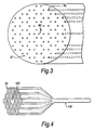
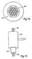
- FIG. 14 Another method of making a fibre is illustrated in figs. 14 and 15.
- a stack of a regular array of capillaries 300 are placed inside a thick-walled silica glass tube 310 (Fig. 14).
- the silica glass tube 310 forms part of the fibre after drawing, serving as a jacket to provide mechanical strength.
- the inside of the tube 310 is evacuated by sealing it within an evacuatable structure while the inside of some or all of the capillaries 300 are kept at a different and higher pressure, for example, because they are left open to the atmosphere.
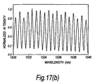
- Fig. 17a shows a fibre according to the invention that is made to be highly birefringent by stacking thicker-walled capillaries at certain sites; smaller air holes 360 are formed at those sites.
- the method according to the invention produces the fibre illustrated in Fig. 17(a) with four selected capillaries terminating within the cylinder 320; the holes in those selected capillaries 300 do not expand during drawing and thereby provide the four small holes 360.
- the fibre of Fig. 17a is highly birefringent because it has only two-fold symmetry resulting from the four smaller holes 360 lying along a diameter of the inner cladding, either side of the core.
- Fig. 17b shows the polarisation beating data of the fibre of Fig. 17a. From the data, the beat length of the fibre can be shown to be 0.92mm at a wavelength of 1550nm; such a beat length is sufficiently short for the fibre to act as a polarisation-maintaining, single mode photonic crystal fibre.
Claims (10)
- Verfahren zur Herstellung einer Photonikkristall-Faser, umfassend:a) Herstellen einer Löcher aufweisenden Vorform,b) Ziehen der Vorform zu einer Faser,
dadurch gekennzeichnet, daß das Verfahren folgenden Schritt aufweist:c) Anlegen einer Druckdifferenz an bestimmte Löcher, um während des Ziehens Änderungen der Faserstruktur zu steuern. - Verfahren nach Anspruch 1, bei dem die Vorform in einem Rohr eingeschlossen ist, das mitgezogen wird und einen Teil der fertigen Faser bildet.
- Verfahren nach Anspruch 1 oder 2, bei dem eine gesteuerte Ausdehnung der Löcher während des Ziehens stattfindet.
- Verfahren nach einem der vorhergehenden Ansprüche, umfassend: (i) Bereitstellen einer Mehrzahl von länglichen, jeweils eine Längsachse, ein erstes und ein zweites Ende aufweisenden Stäben, wobei zumindest einige der Stäbe Kapillaren mit einem parallel zur Längsachse des Stabes vom ersten Ende des Stabes zum zweiten Ende des Stabes verlaufenden Loch sind, (ii) Herstellen der Vorform durch Anordnen der Stäbe zu einem Stapel, wobei die Stäbe mit ihren Längsachsen im wesentlichen parallel zueinander und zur Längsachse des Stapels ausgerichtet werden, (iii) Ziehen des Stapels zur Faser, während das Loch mindestens einer Kapillare in Verbindung mit einer Fluidquelle auf einem ersten Druck gehalten wird, während der Druck um die Kapillare herum auf einem zweiten vom ersten Druck verschiedenen Druck gehalten wird, wobei das Loch mit dem ersten Druck während des Ziehprozesses eine andere Größe erreicht, als es ohne den Druckunterschied erreicht hätte.
- Verfahren nach Anspruch 4, wobei ein ein erstes Ende und ein zweites Ende aufweisendes Rohr den Stapel der Stäbe zu mindestens einem Teil ihrer Länge umgibt und das Innere des Rohrs auf dem zweiten Druck gehalten wird.
- Verfahren nach Anspruch 5, wobei das Rohr die Ausdehnung von mindestens einem der Löcher mit dem ersten inneren Druck einschränkt.
- Verfahren nach Anspruch 5 oder 6, bei dem das Rohr keine Verformung erfährt, die sich wesentlich von derjenigen unterscheidet, die es ohne den Druckunterschied erfahren würde.
- Verfahren nach einem der Ansprüche 5 bis 7, bei dem während des Ziehprozesses: (A) das Rohr nahe dem ersten Ende zu einem ersten Ende einer evakuierbaren Struktur hin abgedichtet wird und sich das zweite Ende des Rohrs innerhalb der evakuierbaren Struktur befindet, (B) mindestens einige der Kapillaren durch die evakuierbare Struktur hindurch verlaufen und zu deren zweiten Ende hin abgedichtet werden, und (C) die evakuierbare Struktur im wesentlichen evakuiert wird, um den zweiten internen Druck herzustellen.
- Verfahren nach Anspruch 8, bei dem die evakuierbare Struktur ein Metallrohr ist.
- Verfahren nach einem der Ansprüche 4 bis 9, bei dem die Vorform maximal zweifache Rotationssymmetrie entlang irgendeiner der Längsachsen aufweist.
Applications Claiming Priority (5)
| Application Number | Priority Date | Filing Date | Title |
|---|---|---|---|
| GB9903923 | 1999-02-19 | ||
| GBGB9903918.2A GB9903918D0 (en) | 1999-02-19 | 1999-02-19 | Improvements in and relating to photonic crystal fibres |
| GB9903918 | 1999-02-19 | ||
| GBGB9903923.2A GB9903923D0 (en) | 1999-02-19 | 1999-02-19 | Improvements in or relating to photonic crystal fibres |
| EP00903901A EP1153325B2 (de) | 1999-02-19 | 2000-02-18 | doppelbrechende photonische kristallfasern und methoden zu ihrer herstellung |
Related Parent Applications (1)
| Application Number | Title | Priority Date | Filing Date |
|---|---|---|---|
| EP00903901A Division EP1153325B2 (de) | 1999-02-19 | 2000-02-18 | doppelbrechende photonische kristallfasern und methoden zu ihrer herstellung |
Publications (3)
| Publication Number | Publication Date |
|---|---|
| EP1340725A2 EP1340725A2 (de) | 2003-09-03 |
| EP1340725A3 EP1340725A3 (de) | 2004-04-28 |
| EP1340725B1 true EP1340725B1 (de) | 2006-01-25 |
Family
ID=26315163
Family Applications (3)
| Application Number | Title | Priority Date | Filing Date |
|---|---|---|---|
| EP03009883A Expired - Lifetime EP1340725B1 (de) | 1999-02-19 | 2000-02-18 | Herstellungsverfahren einer photonischen Kristallfaser |
| EP03021132A Withdrawn EP1385028A1 (de) | 1999-02-19 | 2000-02-18 | Verbesserungen an oder bezüglich der photonischen Kristallglassfasern |
| EP00903901A Expired - Lifetime EP1153325B2 (de) | 1999-02-19 | 2000-02-18 | doppelbrechende photonische kristallfasern und methoden zu ihrer herstellung |
Family Applications After (2)
| Application Number | Title | Priority Date | Filing Date |
|---|---|---|---|
| EP03021132A Withdrawn EP1385028A1 (de) | 1999-02-19 | 2000-02-18 | Verbesserungen an oder bezüglich der photonischen Kristallglassfasern |
| EP00903901A Expired - Lifetime EP1153325B2 (de) | 1999-02-19 | 2000-02-18 | doppelbrechende photonische kristallfasern und methoden zu ihrer herstellung |
Country Status (11)
| Country | Link |
|---|---|
| US (2) | US6954574B1 (de) |
| EP (3) | EP1340725B1 (de) |
| JP (1) | JP4761624B2 (de) |
| KR (1) | KR100637542B1 (de) |
| CN (2) | CN1178079C (de) |
| AT (2) | ATE250772T1 (de) |
| AU (1) | AU771646B2 (de) |
| CA (1) | CA2362997C (de) |
| DE (2) | DE60005486T3 (de) |
| DK (2) | DK1153325T4 (de) |
| WO (1) | WO2000049436A1 (de) |
Families Citing this family (120)
| Publication number | Priority date | Publication date | Assignee | Title |
|---|---|---|---|---|
| EP1086393B1 (de) | 1998-06-09 | 2004-06-02 | Crystal Fibre A/S | Faser mit photonischer bandlücke |
| US6778747B1 (en) | 1998-09-09 | 2004-08-17 | Corning Incorporated | Radially varying and azimuthally asymmetric optical waveguide fiber |
| EP1340725B1 (de) | 1999-02-19 | 2006-01-25 | Crystal Fibre A/S | Herstellungsverfahren einer photonischen Kristallfaser |
| WO2000060390A1 (en) | 1999-03-30 | 2000-10-12 | Crystal Fibre A/S | Polarisation preserving optical fibre |
| US6822978B2 (en) * | 1999-05-27 | 2004-11-23 | Spectra Physics, Inc. | Remote UV laser system and methods of use |
| US6334017B1 (en) * | 1999-10-26 | 2001-12-25 | Corning Inc | Ring photonic crystal fibers |
| GB9929345D0 (en) | 1999-12-10 | 2000-02-02 | Univ Bath | Improvements in and related to photonic-crystal fibres and photonic-crystal fibe devices |
| GB9929344D0 (en) | 1999-12-10 | 2000-02-02 | Univ Bath | Improvements in or relating to photonic crystal fibres |
| KR100758519B1 (ko) * | 2000-02-28 | 2007-09-14 | 스미토모덴키고교가부시키가이샤 | 광섬유 |
| US6636677B2 (en) | 2000-02-28 | 2003-10-21 | Sumitomo Electric Industries, Ltd. | Optical fiber |
| US6788865B2 (en) | 2000-03-03 | 2004-09-07 | Nippon Telegraph And Telephone Corporation | Polarization maintaining optical fiber with improved polarization maintaining property |
| DE50108370D1 (de) * | 2000-06-17 | 2006-01-19 | Leica Microsystems | Anordnung zum Untersuchen mikroskopischer Präparate mit einem Scanmikroskop |
| US6792188B2 (en) | 2000-07-21 | 2004-09-14 | Crystal Fibre A/S | Dispersion manipulating fiber |
| GB2365992B (en) | 2000-08-14 | 2002-09-11 | Univ Southampton | Compound glass optical fibres |
| AUPQ968800A0 (en) | 2000-08-25 | 2000-09-21 | University Of Sydney, The | Polymer optical waveguide |
| US6598428B1 (en) * | 2000-09-11 | 2003-07-29 | Schott Fiber Optics, Inc. | Multi-component all glass photonic band-gap fiber |
| US20030056550A1 (en) * | 2000-09-21 | 2003-03-27 | Masatoshi Tanaka | Method of manufacturing photonic crystal fiber |
| US6594429B1 (en) | 2000-10-20 | 2003-07-15 | Lucent Technologies Inc. | Microstructured multimode fiber |
| JP4759816B2 (ja) * | 2001-02-21 | 2011-08-31 | 住友電気工業株式会社 | 光ファイバの製造方法 |
| US6522433B2 (en) * | 2001-02-28 | 2003-02-18 | Optical Switch Corporation | Interference lithography using holey fibers |
| GB2394712B (en) | 2001-03-09 | 2005-10-26 | Crystal Fibre As | Fabrication of microstructured fibres |
| AU2002237219A1 (en) * | 2001-03-12 | 2002-11-11 | Crystal Fibre A/S | Higher-order-mode dispersion compensating photonic crystal fibres |
| US6954575B2 (en) * | 2001-03-16 | 2005-10-11 | Imra America, Inc. | Single-polarization high power fiber lasers and amplifiers |
| US20020150364A1 (en) * | 2001-04-04 | 2002-10-17 | Ian Bassett | Single mode fibre |
| US20020197042A1 (en) * | 2001-04-06 | 2002-12-26 | Shigeo Kittaka | Optical device, and wavelength multiplexing optical recording head |
| CA2443037A1 (en) | 2001-04-11 | 2002-10-24 | Crystal Fibre A/S | Dual core photonic crystal fibers (pcf) with special dispersion properties |
| US20020181911A1 (en) | 2001-04-30 | 2002-12-05 | Wadsworth William John | Optical material and a method for its production |
| AUPR566201A0 (en) | 2001-06-13 | 2001-07-12 | Ryder, Carol | A device for use in construction |
| US7359603B2 (en) | 2001-07-20 | 2008-04-15 | The University Of Syndey | Constructing preforms from capillaries and canes |
| JP3743637B2 (ja) * | 2001-08-23 | 2006-02-08 | 独立行政法人理化学研究所 | フォトニック結晶および光導波素子 |
| EP1696251A3 (de) * | 2001-08-30 | 2013-10-30 | Crystal Fibre A/S | Optische Faser mit hoher numerischer Apertur, Herstellungsverfahren und Anwendung dafür |
| JP3734733B2 (ja) | 2001-09-27 | 2006-01-11 | 日本電信電話株式会社 | 偏波保持光ファイバおよび絶対単一偏波光ファイバ |
| GB0129404D0 (en) * | 2001-12-07 | 2002-01-30 | Blazephotonics Ltd | An arrayed-waveguide grating |
| AU2003201650A1 (en) * | 2002-01-11 | 2003-07-24 | Blazephotonics Limited | A method and apparatus relating to microstructured optical fibres |
| GB0201492D0 (en) * | 2002-01-23 | 2002-03-13 | Blazephotonics Ltd | A method and apparatus relating to optical fibres |
| JP3630664B2 (ja) * | 2002-01-29 | 2005-03-16 | 三菱電線工業株式会社 | 偏波保持フォトニッククリスタルファイバ |
| JP4466813B2 (ja) * | 2002-03-14 | 2010-05-26 | 日本電気硝子株式会社 | ガラスプリフォームおよびその製造方法 |
| US7266275B2 (en) | 2002-03-15 | 2007-09-04 | Crystal Fibre A/S | Nonlinear optical fibre method of its production and use thereof |
| WO2003080524A1 (en) * | 2002-03-20 | 2003-10-02 | Crystal Fibre A/S | Method of drawing microstructured glass optical fibres from a preform |
| JP4158391B2 (ja) * | 2002-03-25 | 2008-10-01 | 住友電気工業株式会社 | 光ファイバおよびその製造方法 |
| KR100439479B1 (ko) * | 2002-04-10 | 2004-07-09 | 학교법인 성균관대학 | 광자결정 광소자 및 이의 응용 |
| JP4137515B2 (ja) | 2002-05-17 | 2008-08-20 | 日本電信電話株式会社 | 分散シフト光ファイバ |
| AU2003229545A1 (en) * | 2002-05-23 | 2003-12-12 | Crystal Fibre A/S | Optical waveguide, method of its production, and its use |
| US20030230118A1 (en) * | 2002-06-12 | 2003-12-18 | Dawes Steven B. | Methods and preforms for drawing microstructured optical fibers |
| FI114860B (fi) * | 2002-06-13 | 2005-01-14 | Photonium Oy | Kuituaihio, aihion kärkiosa ja menetelmä kuidun valmistamiseksi |
| GB2389915A (en) * | 2002-06-20 | 2003-12-24 | Blazephotonics Ltd | Optic fibre with cladding region having rotational symmetry |
| KR100433703B1 (ko) * | 2002-07-19 | 2004-05-31 | 학교법인단국대학 | 고분자 광자결정 광섬유 모재 제조장치 |
| KR100428410B1 (ko) * | 2002-07-29 | 2004-04-28 | 학교법인 성균관대학 | 광자결정 광결합기 및 이의 응용 |
| DE10252764B3 (de) * | 2002-11-13 | 2004-02-12 | Schott Glas | Verfahren zur Herstellung einer faseroptischen, hohlstrukturieren Vorform und Verfahren zur Herstellung von durchgehende Hohlstrukturen enthaltenden optischen Fasern aus der Vorform |
| EP1420276A1 (de) * | 2002-11-15 | 2004-05-19 | Alcatel | Photonik-Kristall-Faser mit Polarizationserhaltung |
| JP3909014B2 (ja) * | 2002-12-11 | 2007-04-25 | 日本電信電話株式会社 | 単一モードフォトニック結晶光ファイバ |
| AU2003290349A1 (en) * | 2002-12-20 | 2004-07-14 | Blazephotonics Limited | Photonic bandgap optical waveguide |
| US7321712B2 (en) | 2002-12-20 | 2008-01-22 | Crystal Fibre A/S | Optical waveguide |
| GB0314485D0 (en) * | 2003-06-20 | 2003-07-23 | Blazephotonics Ltd | Enhanced optical waveguide |
| JP3871053B2 (ja) * | 2003-05-21 | 2007-01-24 | 日本電信電話株式会社 | 分散フラットファイバ |
| GB0317352D0 (en) * | 2003-07-24 | 2003-08-27 | Blazephotonics Ltd | Optical fibres |
| US20050074215A1 (en) | 2003-08-01 | 2005-04-07 | United States Of America As Represented By The Secretary Of The Navy | Fabrication of high air fraction photonic band gap fibers |
| US7873251B2 (en) * | 2003-08-01 | 2011-01-18 | Bayya Shyam S | Photonic band gap germanate glass fibers |
| KR101018376B1 (ko) * | 2003-08-22 | 2011-03-02 | 삼성전자주식회사 | 포토닉 밴드갭 광섬유 |
| EP1700146B1 (de) | 2003-12-19 | 2013-04-10 | NKT Photonics A/S | Fasern mit photonischem kristall mit belastungselementen |
| US7280730B2 (en) | 2004-01-16 | 2007-10-09 | Imra America, Inc. | Large core holey fibers |
| US7724422B2 (en) * | 2004-01-30 | 2010-05-25 | Nufern | Method and apparatus for providing light having a selected polarization with an optical fiber |
| JP3982515B2 (ja) * | 2004-04-21 | 2007-09-26 | 住友電気工業株式会社 | 光結合構造 |
| DE102004059868B3 (de) * | 2004-12-08 | 2006-05-18 | Institut für Physikalische Hochtechnologie e.V. | Anordnung und Verfahren zur Herstellung von strukturhomogenen mikrooptischen Fasern |
| US20060130528A1 (en) * | 2004-12-22 | 2006-06-22 | Nelson Brian K | Method of making a hole assisted fiber device and fiber preform |
| US20060133753A1 (en) * | 2004-12-22 | 2006-06-22 | Nelson Brian K | Hole assisted fiber device and fiber preform |
| EP1846784B1 (de) | 2004-12-30 | 2016-07-20 | Imra America, Inc. | Fasern mit photonischem bandabstand |
| CN1322344C (zh) * | 2005-01-26 | 2007-06-20 | 浙江工业大学 | 双折射光子晶体光纤 |
| GB0506032D0 (en) | 2005-03-24 | 2005-04-27 | Qinetiq Ltd | Multicore optical fibre |
| US7787729B2 (en) * | 2005-05-20 | 2010-08-31 | Imra America, Inc. | Single mode propagation in fibers and rods with large leakage channels |
| EP1902341A2 (de) | 2005-07-08 | 2008-03-26 | Koheras A/S | Blauerweiterte super-kontinuum-lichtquelle |
| US7391561B2 (en) | 2005-07-29 | 2008-06-24 | Aculight Corporation | Fiber- or rod-based optical source featuring a large-core, rare-earth-doped photonic-crystal device for generation of high-power pulsed radiation and method |
| EP1798581A1 (de) * | 2005-12-16 | 2007-06-20 | Danmarks Tekniske Universitet | Optische Bandlückenfaser mit verschiedenen Verkleidungselementen |
| US7793521B2 (en) * | 2006-03-01 | 2010-09-14 | Corning Incorporated | Method enabling dual pressure control within fiber preform during fiber fabrication |
| US7430345B2 (en) | 2006-03-02 | 2008-09-30 | The Board Of Trustees Of The Leland Stanford Junior University | Polarization controller using a hollow-core photonic-bandgap fiber |
| CN100395573C (zh) * | 2006-03-07 | 2008-06-18 | 北京交通大学 | 一种太赫兹波纤维波导 |
| JP2007264331A (ja) * | 2006-03-29 | 2007-10-11 | Fujikura Ltd | 拡張三角格子型フォトニックバンドギャップファイバ |
| JP4929833B2 (ja) * | 2006-05-17 | 2012-05-09 | 旭硝子株式会社 | 光ファイバ製造方法 |
| US8064128B2 (en) * | 2006-12-08 | 2011-11-22 | Nkt Photonics A/S | Deep blue extended super continuum light source |
| CN100439951C (zh) * | 2006-12-19 | 2008-12-03 | 浙江工业大学 | 一种光子晶体光纤 |
| US20080170830A1 (en) * | 2007-01-16 | 2008-07-17 | Fujikura Ltd | Photonic band gap fiber and method of producing the same |
| CN100449341C (zh) * | 2007-02-07 | 2009-01-07 | 南开大学 | 微结构光纤选择填充方法及判断对准系统 |
| US8755658B2 (en) * | 2007-02-15 | 2014-06-17 | Institut National D'optique | Archimedean-lattice microstructured optical fiber |
| WO2008098338A1 (en) * | 2007-02-15 | 2008-08-21 | Institut National D'optique | Archimedean-lattice microstructured optical fiber |
| CN100592114C (zh) * | 2007-05-11 | 2010-02-24 | 江苏大学 | 一种微结构保偏光纤 |
| CN103246014B (zh) * | 2007-09-26 | 2015-12-23 | Imra美国公司 | 玻璃大芯径光纤 |
| WO2010052815A1 (ja) * | 2008-11-05 | 2010-05-14 | 株式会社フジクラ | フォトニックバンドギャップファイバ |
| KR101055312B1 (ko) * | 2009-01-05 | 2011-08-09 | 한국과학기술연구원 | 포토닉 밴드갭 광섬유 및 그 제조 방법 |
| US8285098B2 (en) * | 2009-03-31 | 2012-10-09 | Imra America, Inc. | Wide bandwidth, low loss photonic bandgap fibers |
| US20100303429A1 (en) * | 2009-05-26 | 2010-12-02 | The Government Of The United States Of America, As Represented By The Secretary Of The Navy | Microstructured Optical Fiber Draw Method with In-Situ Vacuum Assisted Preform Consolidation |
| JP5155987B2 (ja) * | 2009-11-09 | 2013-03-06 | 日立電線株式会社 | 光ファイバの端部加工方法および光ファイバの端部加工装置 |
| WO2011060817A1 (en) * | 2009-11-19 | 2011-05-26 | Vrije Universiteit Brussel | Optical fiber structure for sensors |
| US20110162527A1 (en) * | 2010-01-07 | 2011-07-07 | Graham Gibson | Microstructured Fibre Frit |
| RU2437129C1 (ru) * | 2010-03-24 | 2011-12-20 | Закрытое акционерное общество "Профотек" | Способ изготовления двулучепреломляющего микроструктурного оптического волокна |
| CN101825742B (zh) * | 2010-05-11 | 2011-08-17 | 中国计量学院 | 一种使光子晶体光纤实现起偏的方法 |
| EP2585863B1 (de) * | 2010-06-25 | 2018-10-03 | NKT Photonics A/S | Einzelmodus-glasfaser mit grossem kernbereich |
| US20120007584A1 (en) * | 2010-07-12 | 2012-01-12 | Honeywell International Inc. | Fiber current sensor with reduced temperature sensitivity |
| US9416042B2 (en) * | 2010-12-06 | 2016-08-16 | The United States Of America, As Represented By The Secretary Of The Navy | Hexagonal tube stacking method for the fabrication of hollow core photonic band gap fibers and preforms |
| WO2014031176A1 (en) * | 2012-08-18 | 2014-02-27 | Ofs Fitel, Llc | High-birefringence hollow-core fibers and techniques for making same |
| CN102815864B (zh) * | 2012-09-21 | 2015-01-07 | 中国电子科技集团公司第四十六研究所 | 一种光子晶体光纤的制备方法 |
| US9841557B2 (en) | 2013-07-10 | 2017-12-12 | Nkt Photonics A/S | Microstructured optical fiber, supercontinuum light source comprising microstructured optical fiber and use of such light source |
| GB2562687B (en) * | 2013-09-20 | 2019-05-22 | Univ Southampton | Methods of manufacturing hollow-core photonic bandgap fibers. |
| GB2518419B (en) | 2013-09-20 | 2019-05-29 | Univ Southampton | Hollow-core photonic bandgap fibers |
| DK3047319T3 (da) | 2013-09-20 | 2021-07-05 | Univ Southampton | Fotoniske båndgabfibre med hul kerne og fremgangsmåder til fremstilling deraf |
| PL227732B1 (pl) * | 2013-12-04 | 2018-01-31 | Polskie Centrum Fotoniki I Swiatlowodów | Mikrostrukturalny światłowód z selektywnie powiększonymi przestrzeniami o zmniejszonym współczynniku załamania światła zwłaszcza do generacji efektów nieliniowych i pomiaru naprężeń |
| US9366872B2 (en) | 2014-02-18 | 2016-06-14 | Lockheed Martin Corporation | Apparatus and method for fiber-laser output-beam shaping for spectral beam combination |
| WO2016206700A1 (en) * | 2015-06-25 | 2016-12-29 | Nkt Photonics A/S | A delivery fiber assembly and a broad band source |
| US11072554B2 (en) | 2015-11-10 | 2021-07-27 | Nkt Photonics A/S | Element for a preform, a fiber production method and an optical fiber drawn from the preform |
| SG11201804738SA (en) | 2015-12-23 | 2018-07-30 | Nkt Photonics As | Hollow core optical fiber and a laser system |
| WO2017108060A1 (en) | 2015-12-23 | 2017-06-29 | Nkt Photonics A/S | Photonic crystal fiber assembly |
| US20190135679A1 (en) | 2016-04-27 | 2019-05-09 | Nkt Photonics A/S | A method of fiber production |
| US10698154B2 (en) * | 2017-10-11 | 2020-06-30 | Ofs Fitel, Llc | Suppressing surface modes in fibers |
| US11787727B2 (en) | 2018-04-18 | 2023-10-17 | Lawrence Livermore National Security, Llc | Method for fabrication of sleeveless photonic crystal canes with an arbitrary shape |
| CN108490534B (zh) * | 2018-05-24 | 2020-03-17 | 重庆邮电大学 | 一种基于圆孔混合型微结构光纤的温度不敏感偏振滤波器 |
| GB201810095D0 (en) | 2018-06-20 | 2018-08-08 | Univ Edinburgh | Coherent imaging fibre and method |
| CN109254348B (zh) * | 2018-12-07 | 2023-12-15 | 陕西格物旭光科技有限公司 | 一种填充液体和钛线的双芯光子晶体光纤偏振分束器 |
| KR102186972B1 (ko) * | 2019-08-26 | 2020-12-04 | 한국전력공사 | 편광 유지 광자 결정 광섬유에 새겨진 장주기 광섬유 격자를 포함하는 온도 및 스트레인 동시 측정용 센서 및 이를 이용한 온도 및 스트레인 동시 측정 방법 |
| CN111977959B (zh) * | 2020-08-25 | 2021-10-22 | 东北大学 | 用气压控制气孔尺寸的v型高双折射微结构光纤及其制法 |
| GB202102221D0 (en) | 2021-02-17 | 2021-03-31 | Lumenisity Ltd | Method for dividing optical fibre |
| WO2023019261A1 (en) * | 2021-08-12 | 2023-02-16 | President And Fellows Of Harvard College | Ultraviolet filtering photonic materials |
Family Cites Families (20)
| Publication number | Priority date | Publication date | Assignee | Title |
|---|---|---|---|---|
| US4127398A (en) * | 1963-09-18 | 1978-11-28 | Ni-Tec, Inc. | Multiple-channel tubular devices |
| US3990874A (en) | 1965-09-24 | 1976-11-09 | Ni-Tec, Inc. | Process of manufacturing a fiber bundle |
| US3516239A (en) * | 1966-03-15 | 1970-06-23 | Teijin Ltd | Artificial fiber having voids and method of manufacture thereof |
| SU753797A1 (ru) | 1978-03-01 | 1980-08-07 | Предприятие П/Я Р-6681 | Способ изготовлени многоканальных блоков и устройство дл его осуществлени |
| JPS5992940A (ja) * | 1982-11-17 | 1984-05-29 | Furukawa Electric Co Ltd:The | 空孔を有する光フアイバの製造方法 |
| US4551162A (en) * | 1984-10-01 | 1985-11-05 | Polaroid Corporation | Hollow tube method for forming an optical fiber |
| US5056888A (en) * | 1989-07-17 | 1991-10-15 | Minnesota Mining And Manufacturing Company | Single-mode, single-polarization optical fiber |
| US5155792A (en) * | 1991-06-27 | 1992-10-13 | Hughes Aircraft Company | Low index of refraction optical fiber with tubular core and/or cladding |
| FR2683053B1 (fr) | 1991-10-29 | 1994-10-07 | Thomson Csf | Fibre optique et procede de fabrication. |
| US5802236A (en) * | 1997-02-14 | 1998-09-01 | Lucent Technologies Inc. | Article comprising a micro-structured optical fiber, and method of making such fiber |
| DE69707201T2 (de) * | 1996-05-31 | 2002-06-06 | Lucent Technologies Inc | Artikel mit einer mikrostrukturierten optischen Faser und Verfahren zur Herstellung einer solchen Faser |
| US5841131A (en) | 1997-07-07 | 1998-11-24 | Schlumberger Technology Corporation | Fiber optic pressure transducers and pressure sensing system incorporating same |
| GB9713422D0 (en) * | 1997-06-26 | 1997-08-27 | Secr Defence | Single mode optical fibre |
| US6228787B1 (en) * | 1998-07-27 | 2001-05-08 | Eugen Pavel | Fluorescent photosensitive glasses and process for the production thereof |
| EP1119523B1 (de) | 1998-07-30 | 2010-11-10 | Corning Incorporated | Verfahren zur herstellung photonischen strukturen |
| BR9913724A (pt) | 1998-09-15 | 2001-05-29 | Corning Inc | Guias de onda tendo estrutura que varia axialmente |
| US6243522B1 (en) | 1998-12-21 | 2001-06-05 | Corning Incorporated | Photonic crystal fiber |
| GB9903918D0 (en) * | 1999-02-19 | 1999-04-14 | Univ Bath | Improvements in and relating to photonic crystal fibres |
| EP1340725B1 (de) | 1999-02-19 | 2006-01-25 | Crystal Fibre A/S | Herstellungsverfahren einer photonischen Kristallfaser |
| AU2003201650A1 (en) | 2002-01-11 | 2003-07-24 | Blazephotonics Limited | A method and apparatus relating to microstructured optical fibres |
-
2000
- 2000-02-18 EP EP03009883A patent/EP1340725B1/de not_active Expired - Lifetime
- 2000-02-18 CN CNB00803964XA patent/CN1178079C/zh not_active Expired - Lifetime
- 2000-02-18 US US09/890,793 patent/US6954574B1/en not_active Expired - Lifetime
- 2000-02-18 DK DK00903901T patent/DK1153325T4/da active
- 2000-02-18 CN CNB2004100881551A patent/CN1329755C/zh not_active Expired - Lifetime
- 2000-02-18 EP EP03021132A patent/EP1385028A1/de not_active Withdrawn
- 2000-02-18 DE DE60005486T patent/DE60005486T3/de not_active Expired - Lifetime
- 2000-02-18 AT AT00903901T patent/ATE250772T1/de not_active IP Right Cessation
- 2000-02-18 DK DK03009883T patent/DK1340725T3/da active
- 2000-02-18 EP EP00903901A patent/EP1153325B2/de not_active Expired - Lifetime
- 2000-02-18 AT AT03009883T patent/ATE316516T1/de not_active IP Right Cessation
- 2000-02-18 AU AU25650/00A patent/AU771646B2/en not_active Expired
- 2000-02-18 JP JP2000600121A patent/JP4761624B2/ja not_active Expired - Lifetime
- 2000-02-18 CA CA002362997A patent/CA2362997C/en not_active Expired - Fee Related
- 2000-02-18 KR KR1020017010514A patent/KR100637542B1/ko not_active IP Right Cessation
- 2000-02-18 WO PCT/GB2000/000600 patent/WO2000049436A1/en active IP Right Grant
- 2000-02-18 DE DE60025766T patent/DE60025766T2/de not_active Expired - Lifetime
-
2003
- 2003-11-07 US US10/702,733 patent/US6888992B2/en not_active Expired - Lifetime
Also Published As
| Publication number | Publication date |
|---|---|
| JP2002537575A (ja) | 2002-11-05 |
| DK1153325T4 (da) | 2007-06-18 |
| JP4761624B2 (ja) | 2011-08-31 |
| EP1153325B2 (de) | 2007-03-07 |
| CA2362997C (en) | 2008-04-29 |
| CN1645174A (zh) | 2005-07-27 |
| DE60005486T3 (de) | 2007-07-12 |
| EP1385028A1 (de) | 2004-01-28 |
| AU771646B2 (en) | 2004-04-01 |
| CN1178079C (zh) | 2004-12-01 |
| DE60005486D1 (de) | 2003-10-30 |
| EP1153325A1 (de) | 2001-11-14 |
| ATE316516T1 (de) | 2006-02-15 |
| DK1153325T3 (da) | 2004-01-26 |
| EP1153325B1 (de) | 2003-09-24 |
| KR100637542B1 (ko) | 2006-10-20 |
| KR20010113696A (ko) | 2001-12-28 |
| AU2565000A (en) | 2000-09-04 |
| CN1341221A (zh) | 2002-03-20 |
| DK1340725T3 (da) | 2006-04-18 |
| US20040105641A1 (en) | 2004-06-03 |
| EP1340725A2 (de) | 2003-09-03 |
| EP1340725A3 (de) | 2004-04-28 |
| ATE250772T1 (de) | 2003-10-15 |
| WO2000049436A1 (en) | 2000-08-24 |
| DE60005486T2 (de) | 2004-07-22 |
| CN1329755C (zh) | 2007-08-01 |
| DE60025766D1 (de) | 2006-04-13 |
| US6954574B1 (en) | 2005-10-11 |
| DE60025766T2 (de) | 2006-10-12 |
| CA2362997A1 (en) | 2000-08-24 |
| US6888992B2 (en) | 2005-05-03 |
Similar Documents
| Publication | Publication Date | Title |
|---|---|---|
| EP1340725B1 (de) | Herstellungsverfahren einer photonischen Kristallfaser | |
| EP1700146B1 (de) | Fasern mit photonischem kristall mit belastungselementen | |
| US6990282B2 (en) | Photonic crystal fibers | |
| EP1388018B1 (de) | Eine mikrostrukturierte optische Faser | |
| US8215129B2 (en) | Method of drawing microstructured glass optical fibers from a preform, and a preform combined with a connector | |
| US7106932B2 (en) | Method and apparatus relating to optical fibers | |
| WO2003079074A1 (en) | Improved nonlinear optical fibre method of its production and use thereof | |
| EP1420276A1 (de) | Photonik-Kristall-Faser mit Polarizationserhaltung | |
| US7805038B2 (en) | Birefringent photonic bandgap optical waveguide | |
| WO2004001461A1 (en) | Improvements in and relating to microstructured optical fibres | |
| AU2004202828B2 (en) | Improvements in or relating to photonic crystal fibres | |
| GB2386435A (en) | Microstructured optical fibre | |
| US20060008218A1 (en) | Method of manufacturing an optical fibre, a preform and an optical fibre | |
| WO2003058310A2 (en) | Improvements in and relating to optical fibres |
Legal Events
| Date | Code | Title | Description |
|---|---|---|---|
| PUAI | Public reference made under article 153(3) epc to a published international application that has entered the european phase |
Free format text: ORIGINAL CODE: 0009012 |
|
| AC | Divisional application: reference to earlier application |
Ref document number: 1153325 Country of ref document: EP Kind code of ref document: P |
|
| AK | Designated contracting states |
Kind code of ref document: A2 Designated state(s): AT BE CH CY DE DK ES FI FR GB GR IE IT LI LU MC NL PT SE |
|
| PUAL | Search report despatched |
Free format text: ORIGINAL CODE: 0009013 |
|
| AK | Designated contracting states |
Kind code of ref document: A3 Designated state(s): AT BE CH CY DE DK ES FI FR GB GR IE IT LI LU MC NL PT SE |
|
| RIC1 | Information provided on ipc code assigned before grant |
Ipc: 7C 03B 37/027 B Ipc: 7C 03B 37/012 B Ipc: 7G 02B 6/16 B Ipc: 7C 03B 37/075 A |
|
| RAP1 | Party data changed (applicant data changed or rights of an application transferred) |
Owner name: CRYSTAL FIBRE A/S |
|
| 17P | Request for examination filed |
Effective date: 20041022 |
|
| AKX | Designation fees paid |
Designated state(s): AT BE CH CY DE DK ES FI FR GB GR IE IT LI LU MC NL PT SE |
|
| GRAP | Despatch of communication of intention to grant a patent |
Free format text: ORIGINAL CODE: EPIDOSNIGR1 |
|
| GRAS | Grant fee paid |
Free format text: ORIGINAL CODE: EPIDOSNIGR3 |
|
| GRAA | (expected) grant |
Free format text: ORIGINAL CODE: 0009210 |
|
| AC | Divisional application: reference to earlier application |
Ref document number: 1153325 Country of ref document: EP Kind code of ref document: P |
|
| AK | Designated contracting states |
Kind code of ref document: B1 Designated state(s): AT BE CH CY DE DK ES FI FR GB GR IE IT LI LU MC NL PT SE |
|
| PG25 | Lapsed in a contracting state [announced via postgrant information from national office to epo] |
Ref country code: IT Free format text: LAPSE BECAUSE OF FAILURE TO SUBMIT A TRANSLATION OF THE DESCRIPTION OR TO PAY THE FEE WITHIN THE PRESCRIBED TIME-LIMIT;WARNING: LAPSES OF ITALIAN PATENTS WITH EFFECTIVE DATE BEFORE 2007 MAY HAVE OCCURRED AT ANY TIME BEFORE 2007. THE CORRECT EFFECTIVE DATE MAY BE DIFFERENT FROM THE ONE RECORDED. Effective date: 20060125 Ref country code: AT Free format text: LAPSE BECAUSE OF FAILURE TO SUBMIT A TRANSLATION OF THE DESCRIPTION OR TO PAY THE FEE WITHIN THE PRESCRIBED TIME-LIMIT Effective date: 20060125 Ref country code: CH Free format text: LAPSE BECAUSE OF FAILURE TO SUBMIT A TRANSLATION OF THE DESCRIPTION OR TO PAY THE FEE WITHIN THE PRESCRIBED TIME-LIMIT Effective date: 20060125 Ref country code: BE Free format text: LAPSE BECAUSE OF FAILURE TO SUBMIT A TRANSLATION OF THE DESCRIPTION OR TO PAY THE FEE WITHIN THE PRESCRIBED TIME-LIMIT Effective date: 20060125 Ref country code: NL Free format text: LAPSE BECAUSE OF FAILURE TO SUBMIT A TRANSLATION OF THE DESCRIPTION OR TO PAY THE FEE WITHIN THE PRESCRIBED TIME-LIMIT Effective date: 20060125 Ref country code: LI Free format text: LAPSE BECAUSE OF FAILURE TO SUBMIT A TRANSLATION OF THE DESCRIPTION OR TO PAY THE FEE WITHIN THE PRESCRIBED TIME-LIMIT Effective date: 20060125 |
|
| REG | Reference to a national code |
Ref country code: GB Ref legal event code: FG4D |
|
| RIC1 | Information provided on ipc code assigned before grant |
Ipc: G02B 6/024 00000000ALI20051205BHEP Ipc: C03B 37/012 19850101ALI20051205BHEP Ipc: C03B 37/075 19800101AFI20051205BHEP Ipc: C03B 37/027 19850101ALI20051205BHEP |
|
| REG | Reference to a national code |
Ref country code: CH Ref legal event code: EP |
|
| PG25 | Lapsed in a contracting state [announced via postgrant information from national office to epo] |
Ref country code: IE Free format text: LAPSE BECAUSE OF NON-PAYMENT OF DUE FEES Effective date: 20060220 |
|
| REG | Reference to a national code |
Ref country code: IE Ref legal event code: FG4D |
|
| PG25 | Lapsed in a contracting state [announced via postgrant information from national office to epo] |
Ref country code: MC Free format text: LAPSE BECAUSE OF NON-PAYMENT OF DUE FEES Effective date: 20060228 |
|
| PG25 | Lapsed in a contracting state [announced via postgrant information from national office to epo] |
Ref country code: LU Free format text: LAPSE BECAUSE OF NON-PAYMENT OF DUE FEES Effective date: 20060325 |
|
| REF | Corresponds to: |
Ref document number: 60025766 Country of ref document: DE Date of ref document: 20060413 Kind code of ref document: P |
|
| REG | Reference to a national code |
Ref country code: DK Ref legal event code: T3 |
|
| PG25 | Lapsed in a contracting state [announced via postgrant information from national office to epo] |
Ref country code: ES Free format text: LAPSE BECAUSE OF FAILURE TO SUBMIT A TRANSLATION OF THE DESCRIPTION OR TO PAY THE FEE WITHIN THE PRESCRIBED TIME-LIMIT Effective date: 20060506 |
|
| REG | Reference to a national code |
Ref country code: SE Ref legal event code: TRGR |
|
| PG25 | Lapsed in a contracting state [announced via postgrant information from national office to epo] |
Ref country code: PT Free format text: LAPSE BECAUSE OF FAILURE TO SUBMIT A TRANSLATION OF THE DESCRIPTION OR TO PAY THE FEE WITHIN THE PRESCRIBED TIME-LIMIT Effective date: 20060626 |
|
| NLV1 | Nl: lapsed or annulled due to failure to fulfill the requirements of art. 29p and 29m of the patents act | ||
| REG | Reference to a national code |
Ref country code: CH Ref legal event code: PL |
|
| ET | Fr: translation filed | ||
| PLBE | No opposition filed within time limit |
Free format text: ORIGINAL CODE: 0009261 |
|
| STAA | Information on the status of an ep patent application or granted ep patent |
Free format text: STATUS: NO OPPOSITION FILED WITHIN TIME LIMIT |
|
| 26N | No opposition filed |
Effective date: 20061026 |
|
| PG25 | Lapsed in a contracting state [announced via postgrant information from national office to epo] |
Ref country code: GR Free format text: LAPSE BECAUSE OF FAILURE TO SUBMIT A TRANSLATION OF THE DESCRIPTION OR TO PAY THE FEE WITHIN THE PRESCRIBED TIME-LIMIT Effective date: 20060426 |
|
| PG25 | Lapsed in a contracting state [announced via postgrant information from national office to epo] |
Ref country code: CY Free format text: LAPSE BECAUSE OF FAILURE TO SUBMIT A TRANSLATION OF THE DESCRIPTION OR TO PAY THE FEE WITHIN THE PRESCRIBED TIME-LIMIT Effective date: 20060125 |
|
| REG | Reference to a national code |
Ref country code: FR Ref legal event code: PLFP Year of fee payment: 17 |
|
| REG | Reference to a national code |
Ref country code: FR Ref legal event code: PLFP Year of fee payment: 18 |
|
| REG | Reference to a national code |
Ref country code: FR Ref legal event code: PLFP Year of fee payment: 19 |
|
| PGFP | Annual fee paid to national office [announced via postgrant information from national office to epo] |
Ref country code: FI Payment date: 20190228 Year of fee payment: 20 Ref country code: GB Payment date: 20190228 Year of fee payment: 20 Ref country code: DE Payment date: 20190228 Year of fee payment: 20 |
|
| PGFP | Annual fee paid to national office [announced via postgrant information from national office to epo] |
Ref country code: DK Payment date: 20190228 Year of fee payment: 20 Ref country code: FR Payment date: 20190228 Year of fee payment: 20 Ref country code: SE Payment date: 20190228 Year of fee payment: 20 |
|
| REG | Reference to a national code |
Ref country code: DE Ref legal event code: R071 Ref document number: 60025766 Country of ref document: DE |
|
| REG | Reference to a national code |
Ref country code: DK Ref legal event code: EUP Expiry date: 20200218 |
|
| REG | Reference to a national code |
Ref country code: GB Ref legal event code: PE20 Expiry date: 20200217 |
|
| REG | Reference to a national code |
Ref country code: FI Ref legal event code: MAE |
|
| REG | Reference to a national code |
Ref country code: SE Ref legal event code: EUG |
|
| PG25 | Lapsed in a contracting state [announced via postgrant information from national office to epo] |
Ref country code: GB Free format text: LAPSE BECAUSE OF EXPIRATION OF PROTECTION Effective date: 20200217 |