EP1336769A2 - Trommelbremse mit zwei Betriebsarten - Google Patents
Trommelbremse mit zwei Betriebsarten Download PDFInfo
- Publication number
- EP1336769A2 EP1336769A2 EP03290350A EP03290350A EP1336769A2 EP 1336769 A2 EP1336769 A2 EP 1336769A2 EP 03290350 A EP03290350 A EP 03290350A EP 03290350 A EP03290350 A EP 03290350A EP 1336769 A2 EP1336769 A2 EP 1336769A2
- Authority
- EP
- European Patent Office
- Prior art keywords
- brake
- lever
- shoe
- brake lever
- free end
- Prior art date
- Legal status (The legal status is an assumption and is not a legal conclusion. Google has not performed a legal analysis and makes no representation as to the accuracy of the status listed.)
- Withdrawn
Links
- 230000009977 dual effect Effects 0.000 title claims abstract description 20
- 230000008901 benefit Effects 0.000 description 3
- 238000013461 design Methods 0.000 description 3
- 230000007246 mechanism Effects 0.000 description 2
- 230000007480 spreading Effects 0.000 description 2
- 239000006096 absorbing agent Substances 0.000 description 1
- 238000013459 approach Methods 0.000 description 1
- 230000006872 improvement Effects 0.000 description 1
- 238000003780 insertion Methods 0.000 description 1
- 230000037431 insertion Effects 0.000 description 1
- 238000000034 method Methods 0.000 description 1
- 238000012986 modification Methods 0.000 description 1
- 230000004048 modification Effects 0.000 description 1
- 230000002093 peripheral effect Effects 0.000 description 1
- 230000008569 process Effects 0.000 description 1
- 230000035939 shock Effects 0.000 description 1
Images


Classifications
-
- F—MECHANICAL ENGINEERING; LIGHTING; HEATING; WEAPONS; BLASTING
- F16—ENGINEERING ELEMENTS AND UNITS; GENERAL MEASURES FOR PRODUCING AND MAINTAINING EFFECTIVE FUNCTIONING OF MACHINES OR INSTALLATIONS; THERMAL INSULATION IN GENERAL
- F16D—COUPLINGS FOR TRANSMITTING ROTATION; CLUTCHES; BRAKES
- F16D65/00—Parts or details
- F16D65/14—Actuating mechanisms for brakes; Means for initiating operation at a predetermined position
- F16D65/16—Actuating mechanisms for brakes; Means for initiating operation at a predetermined position arranged in or on the brake
- F16D65/22—Actuating mechanisms for brakes; Means for initiating operation at a predetermined position arranged in or on the brake adapted for pressing members apart, e.g. for drum brakes
-
- F—MECHANICAL ENGINEERING; LIGHTING; HEATING; WEAPONS; BLASTING
- F16—ENGINEERING ELEMENTS AND UNITS; GENERAL MEASURES FOR PRODUCING AND MAINTAINING EFFECTIVE FUNCTIONING OF MACHINES OR INSTALLATIONS; THERMAL INSULATION IN GENERAL
- F16D—COUPLINGS FOR TRANSMITTING ROTATION; CLUTCHES; BRAKES
- F16D51/00—Brakes with outwardly-movable braking members co-operating with the inner surface of a drum or the like
- F16D51/46—Self-tightening brakes with pivoted brake shoes, i.e. the braked member increases the braking action
- F16D51/48—Self-tightening brakes with pivoted brake shoes, i.e. the braked member increases the braking action with two linked or directly-interacting brake shoes
-
- F—MECHANICAL ENGINEERING; LIGHTING; HEATING; WEAPONS; BLASTING
- F16—ENGINEERING ELEMENTS AND UNITS; GENERAL MEASURES FOR PRODUCING AND MAINTAINING EFFECTIVE FUNCTIONING OF MACHINES OR INSTALLATIONS; THERMAL INSULATION IN GENERAL
- F16D—COUPLINGS FOR TRANSMITTING ROTATION; CLUTCHES; BRAKES
- F16D2121/00—Type of actuator operation force
- F16D2121/14—Mechanical
-
- F—MECHANICAL ENGINEERING; LIGHTING; HEATING; WEAPONS; BLASTING
- F16—ENGINEERING ELEMENTS AND UNITS; GENERAL MEASURES FOR PRODUCING AND MAINTAINING EFFECTIVE FUNCTIONING OF MACHINES OR INSTALLATIONS; THERMAL INSULATION IN GENERAL
- F16D—COUPLINGS FOR TRANSMITTING ROTATION; CLUTCHES; BRAKES
- F16D2125/00—Components of actuators
- F16D2125/18—Mechanical mechanisms
- F16D2125/58—Mechanical mechanisms transmitting linear movement
- F16D2125/60—Cables or chains, e.g. Bowden cables
-
- F—MECHANICAL ENGINEERING; LIGHTING; HEATING; WEAPONS; BLASTING
- F16—ENGINEERING ELEMENTS AND UNITS; GENERAL MEASURES FOR PRODUCING AND MAINTAINING EFFECTIVE FUNCTIONING OF MACHINES OR INSTALLATIONS; THERMAL INSULATION IN GENERAL
- F16D—COUPLINGS FOR TRANSMITTING ROTATION; CLUTCHES; BRAKES
- F16D2125/00—Components of actuators
- F16D2125/18—Mechanical mechanisms
- F16D2125/58—Mechanical mechanisms transmitting linear movement
- F16D2125/64—Levers
Definitions
- This invention relates to a drum brake device and more specifically to a dual mode type drum brake which functions as a leading-trailing (LT) type brake device during the service brake operation and functions as a duo servo (DS) type brake device during the parking brake operation.
- LT leading-trailing
- DS duo servo
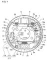
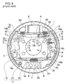
- a back plate 1 has a central hole 1 a freely fitting over an axle of a vehicle, and four bolts, not shown in the figures, are inserted through four bolt holes 1 b for a purpose of fixing the same on a stationary portion of the vehicle.
- a pair of facing first and second brake shoes 2 and 3 is provided, each makes a T-shape in cross-section as a shoe rim 2a is formed together with a shoe web 2b while a shoe rim 3a is formed together with a shoe web 3b, and linings 2c and 3c are adhered on peripheral surfaces of the shoe rims 2a and 3a respectively.
- the brake shoes 2 and 3 are movably mounted on the back plate 1 by conventional shoe-hold mechanisms 4 and 5, each composed of a plate spring and a pin.
- a wheel cylinder 6 functioning as a service brake actuator is arranged between adjacent upper ends 2d and 3d of the brake shoes 2 and 3, which is fixed on the back plate 1.
- An anchor block 7 is arranged between adjacent lower ends 2e and 3e of the brake shoes 2 and 3, which is fixed on a protrusion of the back plate 1 by two rivets 8 and 8.
- An extensible shoe clearance adjustment device 9 composed of an adjustment bolt 10, an adjustment nut 11 and a socket 12, extends between the pair of brake shoes 2 and 3.
- Tools such as a screwdriver may be inserted from an insertion hole 1c (Fig. 7) formed on the back plate 1 or a hole formed on a brake drum, not shown in the figures; and adjustment teeth 10a formed on the adjustment bolt 10 are manually rotated to screw the adjustment bolt 10 in or out from the adjustment nut 11 so as to adjust the shoe clearance.
- Figures 6 and 7 disclose an automatic shoe clearance adjustment mechanism composed of an adjustment lever 13, an adjustment spring 14 and a pin 15, the explanation of which is limited to a anti-vibratory function to the pivot lever 16 and the parking brake actuator 17.
- the pivot lever 16 is constantly urged to be clockwise, via the pin 15 which also pivotally supports the adjustment lever 13 and is integrated with the pivot lever 16, due to a spring force of the adjustment spring 14, thereby suppressing the vibration of the pivot lever 16 and the parking brake actuator 17.
- a central region of the pivot lever 16 or a portion of the pivot lever 16 between an abutment point with the shoe clearance adjustment device 9 and an abutment point with a later described strut 20 in Figures 6 is pivotally supported on the first brake shoe 2 around a pivot section 16c.
- An upper end 16a and a lower end 16b of the pivot lever 16 respectively make a functional engagement with the shoe clearance adjustment device 9 and the strut 20.
- a parking brake actuator 17 composed of a brake lever 18, the strut 20 and a pin 21 is provided adjacent to the anchor block 7.
- the brake lever 18 is designed such that the proximal portion 18a of the brake lever 18 is pivotally supported on the second brake shoe 3 around the pin 21 adjacent to the anchor block 7.
- a cable end 23a on the tip of the brake cable 23 arranged through a guide pipe 26 fixed on the back plate 1 is hooked and rested on a free end 18b of the brake lever 18 at the wheel cylinder 6 side.
- the strut 20 extends between a portion on the brake lever 18 adjacent to the proximal portion 18a and the lower end 16b of the pivot lever 16.
- a shoe return spring 24 is stretched between the upper ends of the brake shoes 2 and 3 while a shoe return spring 25 is stretched between the lower ends of the brake shoes 2 and 3, urging the brake shoes 2 and 3 to approach each other, and upper facing portions of the brake shoes 2 and 3 engage and abut against the shoe clearance adjustment device 9 while lower facing ends 2e and 3e engage and abut against the anchor block 7.
- a hand lever not shown in the figures, is operated to pull the brake cable 23 toward the first brake shoe 2 side, and the brake lever 18 rotates clockwise in Figure 6 around the pin 21 to press the strut 20.
- the pressing force on the strut 20 rotates the pivot lever 16 counterclockwise around the pivot section 16c spreading the second brake shoe 3 open via the shoe clearance adjustment device 9.
- the pivot lever 16 rotates counterclockwise with an abutment point between the pivot lever 16 and the shoe clearance adjustment device 9, thereby spreading the first brake shoe 2 open due to the pressing force acting on the pivot section 16c of the pivot lever 16.
- a reaction force of the brake lever 18 acts on the lower end 3e of the second brake shoe 3 via the pin 21 with abutment point between the brake lever 18 and the strut 20. Accordingly, linings 2c and 3c of both brake shoes 2 and 3 frictionally engage with the brake drum, not shown in the figures, thereby keeping the stationary state of the brake drum.
- a frictional force of a primary brake shoe 2 or 3, being caused by a rotational direction of the brake drum, is transmitted to the remaining secondary brake shoe 3 or 2 via the shoe clearance adjustment device 9, thereby functioning as a duo servo type drum brake.
- Figure 8 is an example of a part of chassis at a rear side of the vehicle.
- Figure 8 illustrates drum brakes a and a attached on two-end side surfaces of an axle housing b.
- the left drum brake a only describes a back plate 1 and a wheel cylinder 6 and a right drum brake, explained in Figures 6 and 7, only describes a back plate 1.
- Each wheel cylinder 6, only one of which is illustrated in the left drum brake in Figure 8, is generally positioned at an upper central portion of the back plates 1, 1 in order to avoid damaging a brake pipe and brake hoses c, c in case of a fallen wheel in a gutter, flying gravel, or the like.
- the brake cable 23 is arranged adjacent to the wheel cylinder 6 and extended toward a front side of the vehicle through the guide pipe 26.
- Shock absorbers d and d and coil springs e and e existing at a front side of the vehicle become obstacles for a routing design of the brake cable 23.
- This invention was made to improve the above-points and is to provide a dual mode type drum brake with an improvement in a simple structure of a parking brake actuator, in which a brake cable can be arranged in a lower side of a drum brake relative to an axle, thereby not being interrupted by any chassis parts.
- this invention provides a dual mode drum brake wherein a parking brake actuator is designed such that a first brake lever has a proximal portion pivotally supported on a portion between both ends of a second brake shoe and a second brake lever has a proximal portion pivotally supported on a lower end portion of the second brake shoe.
- a free end of the first brake lever and a free end of the second brake lever extend so as to be in substantially parallel and facing each other.
- the free end of the second brake lever functionally engages with the first brake lever between the proximal portion and the free end of the first brake lever.
- a strut extends between the second brake lever at a portion between the two ends thereof and the lower end side of the pivot lever; and a brake cable to be pulled to activate the free end of the first brake lever is arranged adjacent to the anchor and extended toward the first brake shoe side.
- the dual mode drum brake of this invention may be designed such that the second brake lever is composed of one mono-plate, the proximal portion thereof is formed into two parallel facing forked legs to put the shoe web of the second brake shoe therebetween and a section thereof from an intermediate portion adjacent to an inner circumference of the shoe web to the free end thereof makes an almost C-shape in cross-section. Then, an external surface of a bottom portion or an internal surface of a bottom portion of the C-shaped section functionally engages with the first brake lever.
- a position on the back plate, from which the brake cable pulling the first brake lever is penetrated is located at an anchor side.
- a position on the back plate, from which the brake cable is arranged to pass through, is located at a lower side of the axle. Therefore, no chassis parts become obstacles when routing the brake cable.
- Both the first and the second brake levers may be simply integrally-formed by pressing, and the proximal portion of the second brake lever formed into forked legs putting a shoe web therebetween increases a strength against a biasing force generated due to an operation force of the first brake lever. At the same time, the operation force is transmitted to the strut without being biased.
- a lever-ratio of the brake lever is a value obtained by multiplying lever-ratios of the first brake lever and the second brake lever, which allows a low lever-ratio of each brake lever and enables a design of the brake levers to be thinner and lighter.
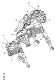
- Example 1 of this invention will be explained with reference to Figures 1 to 3.
- the same reference numbers as in the previous section describing the related art dual mode type drum brake device will be assigned to identical parts or sites having the same functions as described in Example 1, the explanation of which will be omitted here, and the explanation will be focused on the structure of parking brake actuator 117 resolving the problems raised by the conventional arts, which are identified with reference numbers in 100 series.
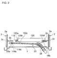
- a parking brake actuator 117 of this example comprises a first brake lever 118, a second brake lever 119 and a strut 120 and so on.
- the first brake lever 118 has a proximal portion 118a which is pivotally supported around a pin 121 between both ends of a second brake shoe 3 while the second brake lever 119 has a proximal portion 119a which is pivotally supported around a pin 122 at a lower end portion 3e of the second brake shoe 3.
- Free ends 118b and 119b of the brake levers 118 and 119 extend so as to be paralleled and faced each other, and the second brake lever 119 is arranged in parallel to the first brake lever 118 at the brake inner side.
- the first brake lever 118 is composed of a mono-plate, which is superposed on a shoe web 3b at a back plate 1 side and has the free end 118b bent and formed in almost U-shape with a groove 118c (see Figs. 2 and 3).
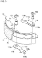
- the second brake lever 119 is also composed of a mono-plate, in which the proximal portion 119a thereof is formed into two parallel facing forked legs to put the shoe web 3b of the second brake shoe 3 therebetween (see Fig. 3).
- the second brake lever 119 is formed almost C-shape in cross-section between an intermediate portion thereof adjacent to an inner circumference of the shoe web 3b and the free end thereof.
- An external surface of a bottom portion of the C-shaped section at the free end 119b functionally abuts and engages with a projection 118d formed between proximal portion 118a and free end 118b of the first brake lever 118, and a left end of the strut 120 functionally abuts and engages with the second brake lever 119 between proximal portion 119a and free end 119b.
- the strut 120 made of a rectangular thin plate has a projection 120a at a left end thereof fitting in the C-shaped section formed on the second brake lever 119 restricting a vertical movement thereof; an upper stepped surface 120b abuts and engages with a bottom of a notched groove 119c formed on an upper leg of the two forked legs of the C-shaped section restricting a horizontal movement thereof.
- the notched groove 119c of the second brake lever 119 is tapered to gradually internally open so as to swing in a vertical direction in Figure 1.
- a lower stepped surface 120c of the strut 120 abuts and engages with a lower leg of the c-shaped section of the second brake lever 119.
- the right end portion of the strut 120 has a notched groove 120d and the bottom thereof abuts and engages with the lower end 16b of the pivot lever 16.
- the strength of the free end 119b of the second brake lever 119 may be increased if an opening of the C-shaped section of the second brake lever 119 as shown in Figure 1 is shaped to draw and to gradually externally close.
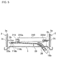
- Example 2 of this invention will be explained with reference to Figures 4 and 5.
- a parking brake actuator 217 of this example is identical to the above-described example 1 except for shapes of a second brake lever 119 and a strut 120, which are identified with reference numbers in 200 series.
- a second brake lever 219 as compared with Example 1 is bent to form a C-shaped section in cross-section from an intermediate portion adjacent to an inner circumference edge of the shoe web 3b to the free end 219b thereof, which has an opening facing outside of the brake.
- a projection 118d of the first brake lever 118 functionally abuts and engages with an internal surface of a bottom of the C-shaped section of the free end 219b.
- a strut 220 made of a rectangular thin plate has a notched groove 220a at the left end which crosses and functionally abuts to engage with a tapered groove or tapered notched groove 219d formed at the C-shaped section of the second brake lever 219.
- this invention has the following advantages.
- the dual mode drum brake of this invention comprises a parking brake actuator consisting of a first and second brake levers instead of the single brake lever of the conventional arts, thereby enabling to pull the brake cable out from a lower side of the axle and facilitating a root of the same without obstacles such as chassis parts.
- a route of the brake cable may be moved from a wheel cylinder side to an anchor side simply by changing the mounting positions of the brake lever and the strut and the arrangement of the guide pipe on the back plate, which improves the designability.
- Two parallel forked legs at the proximal portion of the second brake lever puts the shoe web therebetween, and the operation force of the first brake lever may be transmitted to the strut without being biased, which improves the strength of the parking brake actuator.
- lever-ratio of the brake lever comes in a value obtained by multiplying the lever-ratios of the first and the second brake levers, which results in a low lever-ratio of each brake lever and enables to design the brake levers thinner and lighter.
Landscapes
- Engineering & Computer Science (AREA)
- General Engineering & Computer Science (AREA)
- Mechanical Engineering (AREA)
- Braking Arrangements (AREA)
Applications Claiming Priority (2)
| Application Number | Priority Date | Filing Date | Title |
|---|---|---|---|
| JP2002036667 | 2002-02-14 | ||
| JP2002036667A JP3933487B2 (ja) | 2002-02-14 | 2002-02-14 | デュアルモードドラムブレーキ装置 |
Publications (2)
| Publication Number | Publication Date |
|---|---|
| EP1336769A2 true EP1336769A2 (de) | 2003-08-20 |
| EP1336769A3 EP1336769A3 (de) | 2004-06-16 |
Family
ID=27621417
Family Applications (1)
| Application Number | Title | Priority Date | Filing Date |
|---|---|---|---|
| EP03290350A Withdrawn EP1336769A3 (de) | 2002-02-14 | 2003-02-13 | Trommelbremse mit zwei Betriebsarten |
Country Status (3)
| Country | Link |
|---|---|
| US (1) | US6766887B2 (de) |
| EP (1) | EP1336769A3 (de) |
| JP (1) | JP3933487B2 (de) |
Cited By (2)
| Publication number | Priority date | Publication date | Assignee | Title |
|---|---|---|---|---|
| US6766887B2 (en) * | 2002-02-14 | 2004-07-27 | Nisshinbo Ind. Inc. | Dual mode type drum brake device |
| CN109712513A (zh) * | 2019-03-06 | 2019-05-03 | 滨州学院 | 一种地理学习用多用途地球仪 |
Families Citing this family (6)
| Publication number | Priority date | Publication date | Assignee | Title |
|---|---|---|---|---|
| JP6114106B2 (ja) | 2012-07-25 | 2017-04-12 | 曙ブレーキ工業株式会社 | ドラムブレーキ装置 |
| US10138966B2 (en) | 2014-03-11 | 2018-11-27 | Nissin Kogyo Co., Ltd. | Vehicle brake apparatus |
| JP2015172385A (ja) * | 2014-03-11 | 2015-10-01 | 日信工業株式会社 | 車両用ブレーキ装置 |
| FR3057317B1 (fr) * | 2016-10-12 | 2020-10-30 | Foundation Brakes France | Frein a tambour integrant un levier d'actionnement de frein de stationnement a double flancs encliquetes l'un avec l'autre |
| FR3057318B1 (fr) * | 2016-10-12 | 2020-08-14 | Foundation Brakes France | Frein a tambour integrant un levier d'actionnement de frein de stationnement a double flancs soudes |
| US20240123962A1 (en) * | 2022-10-13 | 2024-04-18 | ZF Active Safety US Inc. | Apparatus for drum brake assembly |
Citations (3)
| Publication number | Priority date | Publication date | Assignee | Title |
|---|---|---|---|---|
| JPS628652A (ja) | 1985-07-05 | 1987-01-16 | Fuji Facom Corp | 網制御装置 |
| US5275260A (en) | 1989-09-18 | 1994-01-04 | Kelsey-Hayes Company | Dual mode drum brake assembly |
| JPH09273573A (ja) | 1996-04-03 | 1997-10-21 | Nisshinbo Ind Inc | ドラムブレーキ装置 |
Family Cites Families (5)
| Publication number | Priority date | Publication date | Assignee | Title |
|---|---|---|---|---|
| JPS5610833A (en) | 1979-07-07 | 1981-02-03 | Toyota Motor Corp | Drum brake |
| JP3838290B2 (ja) * | 1996-06-28 | 2006-10-25 | トヨタ自動車株式会社 | デュアルモードドラムブレーキ |
| JP4084899B2 (ja) * | 1998-12-07 | 2008-04-30 | 豊生ブレーキ工業株式会社 | デュアルモードドラムブレーキ |
| JP2002188665A (ja) * | 2000-12-22 | 2002-07-05 | Nisshinbo Ind Inc | ドラムブレーキ装置 |
| JP3933487B2 (ja) * | 2002-02-14 | 2007-06-20 | 日清紡績株式会社 | デュアルモードドラムブレーキ装置 |
-
2002
- 2002-02-14 JP JP2002036667A patent/JP3933487B2/ja not_active Expired - Fee Related
-
2003
- 2003-02-10 US US10/361,218 patent/US6766887B2/en not_active Expired - Fee Related
- 2003-02-13 EP EP03290350A patent/EP1336769A3/de not_active Withdrawn
Patent Citations (3)
| Publication number | Priority date | Publication date | Assignee | Title |
|---|---|---|---|---|
| JPS628652A (ja) | 1985-07-05 | 1987-01-16 | Fuji Facom Corp | 網制御装置 |
| US5275260A (en) | 1989-09-18 | 1994-01-04 | Kelsey-Hayes Company | Dual mode drum brake assembly |
| JPH09273573A (ja) | 1996-04-03 | 1997-10-21 | Nisshinbo Ind Inc | ドラムブレーキ装置 |
Cited By (3)
| Publication number | Priority date | Publication date | Assignee | Title |
|---|---|---|---|---|
| US6766887B2 (en) * | 2002-02-14 | 2004-07-27 | Nisshinbo Ind. Inc. | Dual mode type drum brake device |
| CN109712513A (zh) * | 2019-03-06 | 2019-05-03 | 滨州学院 | 一种地理学习用多用途地球仪 |
| CN109712513B (zh) * | 2019-03-06 | 2021-02-02 | 滨州学院 | 一种地理学习用多用途地球仪 |
Also Published As
| Publication number | Publication date |
|---|---|
| US20030150676A1 (en) | 2003-08-14 |
| EP1336769A3 (de) | 2004-06-16 |
| JP2003240030A (ja) | 2003-08-27 |
| US6766887B2 (en) | 2004-07-27 |
| JP3933487B2 (ja) | 2007-06-20 |
Similar Documents
| Publication | Publication Date | Title |
|---|---|---|
| EP1336769A2 (de) | Trommelbremse mit zwei Betriebsarten | |
| JP3341147B2 (ja) | ドラムブレーキ装置 | |
| JP5725286B2 (ja) | パッドクリップの組付け構造 | |
| EP1108917A2 (de) | Einbaustruktur für ein Bremsseil für eine Trommelbremse | |
| EP1174627B1 (de) | Bremskabelanschlusselement für Trommelbremsen | |
| US6877590B2 (en) | Dual mode drum brake | |
| EP0026717A1 (de) | Trommelbremsvorrichtung | |
| EP1108916A2 (de) | Einbaustruktur für ein Bremsseil für eine Trommelbremse | |
| JP4672130B2 (ja) | シュー間隙自動調節機構付きドラムブレーキ | |
| US20050145451A1 (en) | Adapter for vehicle brake assembly | |
| EP1031753B1 (de) | Trommelbremsvorrichtung mit zwei Betriebsarten | |
| JP2628791B2 (ja) | 自動調節装置を備えた機械作動形ブレーキ | |
| JP3341149B2 (ja) | ドラムブレーキ装置 | |
| JP4828825B2 (ja) | 自動ケーブルラッチ動作を行うパーキングブレーキアセンブリ | |
| EP0905401A2 (de) | Trommelbremse | |
| JPS6316902Y2 (de) | ||
| JPS6224117Y2 (de) | ||
| JPS639789Y2 (de) | ||
| JP3910460B2 (ja) | ドラムブレーキのケーブルガイド | |
| JPH0449390Y2 (de) | ||
| JPS6135792Y2 (de) | ||
| JPH066297Y2 (ja) | パーキングブレーキ付き車両用ドラムブレーキ | |
| JPS5833312Y2 (ja) | ドラムブレ−キ装置の自動間隙調整装置 | |
| JPS5853471Y2 (ja) | 車両用ドラムブレ−キのリタ−ンスプリング保持板 | |
| JP4530594B2 (ja) | ブレーキ装置のケーブル導入構造 |
Legal Events
| Date | Code | Title | Description |
|---|---|---|---|
| PUAI | Public reference made under article 153(3) epc to a published international application that has entered the european phase |
Free format text: ORIGINAL CODE: 0009012 |
|
| AK | Designated contracting states |
Designated state(s): AT BE BG CH CY CZ DE DK EE ES FI FR GB GR HU IE IT LI LU MC NL PT SE SI SK TR |
|
| AX | Request for extension of the european patent |
Extension state: AL LT LV MK RO |
|
| PUAL | Search report despatched |
Free format text: ORIGINAL CODE: 0009013 |
|
| AK | Designated contracting states |
Kind code of ref document: A3 Designated state(s): AT BE BG CH CY CZ DE DK EE ES FI FR GB GR HU IE IT LI LU MC NL PT SE SI SK TR |
|
| AX | Request for extension of the european patent |
Extension state: AL LT LV MK RO |
|
| RIC1 | Information provided on ipc code assigned before grant |
Ipc: 7F 16D 51/50 A |
|
| AKX | Designation fees paid | ||
| REG | Reference to a national code |
Ref country code: DE Ref legal event code: 8566 |
|
| STAA | Information on the status of an ep patent application or granted ep patent |
Free format text: STATUS: THE APPLICATION IS DEEMED TO BE WITHDRAWN |
|
| 18D | Application deemed to be withdrawn |
Effective date: 20041217 |