EP1336706A1 - Transmission device of the handling force in a door latch - Google Patents
Transmission device of the handling force in a door latch Download PDFInfo
- Publication number
- EP1336706A1 EP1336706A1 EP20030003039 EP03003039A EP1336706A1 EP 1336706 A1 EP1336706 A1 EP 1336706A1 EP 20030003039 EP20030003039 EP 20030003039 EP 03003039 A EP03003039 A EP 03003039A EP 1336706 A1 EP1336706 A1 EP 1336706A1
- Authority
- EP
- European Patent Office
- Prior art keywords
- guide tube
- cover
- handling
- cable
- elastic cap
- Prior art date
- Legal status (The legal status is an assumption and is not a legal conclusion. Google has not performed a legal analysis and makes no representation as to the accuracy of the status listed.)
- Granted
Links
Images


Classifications
-
- F—MECHANICAL ENGINEERING; LIGHTING; HEATING; WEAPONS; BLASTING
- F16—ENGINEERING ELEMENTS AND UNITS; GENERAL MEASURES FOR PRODUCING AND MAINTAINING EFFECTIVE FUNCTIONING OF MACHINES OR INSTALLATIONS; THERMAL INSULATION IN GENERAL
- F16C—SHAFTS; FLEXIBLE SHAFTS; ELEMENTS OR CRANKSHAFT MECHANISMS; ROTARY BODIES OTHER THAN GEARING ELEMENTS; BEARINGS
- F16C1/00—Flexible shafts; Mechanical means for transmitting movement in a flexible sheathing
- F16C1/10—Means for transmitting linear movement in a flexible sheathing, e.g. "Bowden-mechanisms"
- F16C1/107—Sealing details
-
- E—FIXED CONSTRUCTIONS
- E05—LOCKS; KEYS; WINDOW OR DOOR FITTINGS; SAFES
- E05B—LOCKS; ACCESSORIES THEREFOR; HANDCUFFS
- E05B79/00—Mounting or connecting vehicle locks or parts thereof
- E05B79/10—Connections between movable lock parts
- E05B79/20—Connections between movable lock parts using flexible connections, e.g. Bowden cables
-
- E—FIXED CONSTRUCTIONS
- E05—LOCKS; KEYS; WINDOW OR DOOR FITTINGS; SAFES
- E05B—LOCKS; ACCESSORIES THEREFOR; HANDCUFFS
- E05B79/00—Mounting or connecting vehicle locks or parts thereof
- E05B79/10—Connections between movable lock parts
- E05B79/22—Operative connections between handles, sill buttons or lock knobs and the lock unit
-
- F—MECHANICAL ENGINEERING; LIGHTING; HEATING; WEAPONS; BLASTING
- F16—ENGINEERING ELEMENTS AND UNITS; GENERAL MEASURES FOR PRODUCING AND MAINTAINING EFFECTIVE FUNCTIONING OF MACHINES OR INSTALLATIONS; THERMAL INSULATION IN GENERAL
- F16C—SHAFTS; FLEXIBLE SHAFTS; ELEMENTS OR CRANKSHAFT MECHANISMS; ROTARY BODIES OTHER THAN GEARING ELEMENTS; BEARINGS
- F16C1/00—Flexible shafts; Mechanical means for transmitting movement in a flexible sheathing
- F16C1/10—Means for transmitting linear movement in a flexible sheathing, e.g. "Bowden-mechanisms"
- F16C1/20—Construction of flexible members moved to and fro in the sheathing
-
- E—FIXED CONSTRUCTIONS
- E05—LOCKS; KEYS; WINDOW OR DOOR FITTINGS; SAFES
- E05B—LOCKS; ACCESSORIES THEREFOR; HANDCUFFS
- E05B77/00—Vehicle locks characterised by special functions or purposes
- E05B77/34—Protection against weather or dirt, e.g. against water ingress
-
- E—FIXED CONSTRUCTIONS
- E05—LOCKS; KEYS; WINDOW OR DOOR FITTINGS; SAFES
- E05B—LOCKS; ACCESSORIES THEREFOR; HANDCUFFS
- E05B85/00—Details of vehicle locks not provided for in groups E05B77/00 - E05B83/00
- E05B85/10—Handles
-
- F—MECHANICAL ENGINEERING; LIGHTING; HEATING; WEAPONS; BLASTING
- F16—ENGINEERING ELEMENTS AND UNITS; GENERAL MEASURES FOR PRODUCING AND MAINTAINING EFFECTIVE FUNCTIONING OF MACHINES OR INSTALLATIONS; THERMAL INSULATION IN GENERAL
- F16C—SHAFTS; FLEXIBLE SHAFTS; ELEMENTS OR CRANKSHAFT MECHANISMS; ROTARY BODIES OTHER THAN GEARING ELEMENTS; BEARINGS
- F16C2350/00—Machines or articles related to building
- F16C2350/52—Locks, e.g. cables to actuate door locks
-
- Y—GENERAL TAGGING OF NEW TECHNOLOGICAL DEVELOPMENTS; GENERAL TAGGING OF CROSS-SECTIONAL TECHNOLOGIES SPANNING OVER SEVERAL SECTIONS OF THE IPC; TECHNICAL SUBJECTS COVERED BY FORMER USPC CROSS-REFERENCE ART COLLECTIONS [XRACs] AND DIGESTS
- Y10—TECHNICAL SUBJECTS COVERED BY FORMER USPC
- Y10T—TECHNICAL SUBJECTS COVERED BY FORMER US CLASSIFICATION
- Y10T292/00—Closure fasteners
- Y10T292/08—Bolts
- Y10T292/1043—Swinging
- Y10T292/1051—Spring projected
- Y10T292/1052—Operating means
- Y10T292/1057—Flexible
-
- Y—GENERAL TAGGING OF NEW TECHNOLOGICAL DEVELOPMENTS; GENERAL TAGGING OF CROSS-SECTIONAL TECHNOLOGIES SPANNING OVER SEVERAL SECTIONS OF THE IPC; TECHNICAL SUBJECTS COVERED BY FORMER USPC CROSS-REFERENCE ART COLLECTIONS [XRACs] AND DIGESTS
- Y10—TECHNICAL SUBJECTS COVERED BY FORMER USPC
- Y10T—TECHNICAL SUBJECTS COVERED BY FORMER US CLASSIFICATION
- Y10T292/00—Closure fasteners
- Y10T292/28—Extension link
-
- Y—GENERAL TAGGING OF NEW TECHNOLOGICAL DEVELOPMENTS; GENERAL TAGGING OF CROSS-SECTIONAL TECHNOLOGIES SPANNING OVER SEVERAL SECTIONS OF THE IPC; TECHNICAL SUBJECTS COVERED BY FORMER USPC CROSS-REFERENCE ART COLLECTIONS [XRACs] AND DIGESTS
- Y10—TECHNICAL SUBJECTS COVERED BY FORMER USPC
- Y10T—TECHNICAL SUBJECTS COVERED BY FORMER US CLASSIFICATION
- Y10T292/00—Closure fasteners
- Y10T292/57—Operators with knobs or handles
-
- Y—GENERAL TAGGING OF NEW TECHNOLOGICAL DEVELOPMENTS; GENERAL TAGGING OF CROSS-SECTIONAL TECHNOLOGIES SPANNING OVER SEVERAL SECTIONS OF THE IPC; TECHNICAL SUBJECTS COVERED BY FORMER USPC CROSS-REFERENCE ART COLLECTIONS [XRACs] AND DIGESTS
- Y10—TECHNICAL SUBJECTS COVERED BY FORMER USPC
- Y10T—TECHNICAL SUBJECTS COVERED BY FORMER US CLASSIFICATION
- Y10T74/00—Machine element or mechanism
- Y10T74/20—Control lever and linkage systems
- Y10T74/20396—Hand operated
- Y10T74/20402—Flexible transmitter [e.g., Bowden cable]
Definitions
- This invention relates to a force transmission part. handling in a door lock.
- the force transmission part 101 in a conventional door lock has a guide tube 102 and an internal cable 103 inserted into this guide tube guide 102.
- the bottom of the internal cable 103 is linked to a lever handling of the door lock not fitted in the door, and, the top is linked to a movable part 104a of a device for handling 104 installed on the side of the door's exterior panel.
- the handling device 104 is handled in the direction of arrow, internal cable is pulled up and lever handling of the door lock is trained to take its action.
- this invention aims to present a transmission part of the door glass handling force capable of avoiding infiltration of rainwater into the guide tube and ensure stable and lasting operation.
- a cover capable of closing the top of the aforementioned guide tube during the decommissioning of the handling device, is laid on the cable above which comes out from above the above guide tube.
- a cover capable of close the top of the guide tube when decommissioning of the handling device is laid on the cable which leaves the above the aforementioned guide tube. And, it is possible to avoid surely the infiltration of rainwater into the guide tube by means of this cover and ensure a stable and durable operation.
- the underside of the cover is brought into contact with the top of the guide tube, the top of the guide tube is closed and the underside of the lid is wider than the top of the guide tube.
- the rain water flowing from the top of the inner cable is guided to the outside of the guide. And, therefore, it is possible to surely avoid infiltration rainwater in the guide tube.
- a part for transmitting the force of handling in a door lock comprising a tube guide and an internal cable inserted into this guide tube, the bottom of this cable being linked to the lock or a handling device to manipulate said lock, and, the top being linked to the other of the two, the top of the above guide tube is covered by a elastic cap and cover, capable of closing the top of the aforementioned elastic cap when the handling device, is laid on the aforementioned cable which leaves the above the aforementioned elastic cap.
- the top of the tube guide is covered by an elastic cap and a cover, capable of closing the top of the aforementioned elastic cap when the decommissioning of the handling device is placed on the cable coming out of the top of the elastic cap. And, it is possible surely avoid the infiltration of rainwater into the tube guiding by means of this cover and this elastic cap and ensure stable and lasting operation.
- the top of the latter is closed and the underside of the lid is wider than the top of the elastic hood.
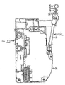
- Figs. 1 and 2 are front views of a door lock 1 and the Fig. 2 is a front view of an upper part of the part transmission 2 of the handling force.
- Door lock 1 is installed in the door of a car. And, a door strike not shown, a removable gear and different levers not shown are housed in cage 3 of this lock.
- Transmission part 2 of the handling force is a cable manipulation, in other words, it has a guide 4 and an internal cable 5 inserted in this guide tube 4.
- the internal cable bottom 5 enters the cage 3 and is linked to a lever external among the various aforementioned levers.
- the bottom of the tube guide 4 is fixed very tightly on the cage 3 so as not to let the rain water flowing over the peripheral surface of the guide tube 4.
- the top of the guide tube 4 is fixed on a part reserved for the attachment not included in the handling device installed on the exterior door panel and a 5a ball end mounted at the top of the internal cable is connected to a movable part of the handling device as in the case of the device classic. Furthermore, the aforementioned handling device is installed above door lock 1.
- Handling force transmission part 2 is installed in a vertical direction in the door and an elastic cap 6 is placed on top of the guide tube 4.
- a metal cover 7 in the form of the disc is mounted in bottom of the end piece 5a of the internal cable 5 exiting from the top of the elastic cap 6. This cover 7 is wider than the top of the elastic cap 6.
- the cover 7 is brought into contact with the top of the elastic cap 6 and, therefore, the top of the guide tube 4 is closed. And, the rainwater A flowing along the internal cable 5 and the handling device is stopped from above the cover 7 and guided to the outer surface of the cap elastic 6. Thus, the infiltration of rainwater into the tube guidance can be avoided.
- the cover 7 is made of metal and fixed securely to the internal cable 5. And, by putting the cover 7 in contact with the above the elastic cap 6, the amount of displacement of the internal cable 5 down is limited and it is easy to connect the bottom of the internal cable 5 to the external lever of the door lock 1.
- the elastic cap 6 it is not essential. In in other words, it is possible to omit the elastic cap 6, to put the underside of the cover 7 directly in contact with the above the guide tube 4, close the top of the guide tube guide 4 and thus avoid the infiltration of rainwater into the guide tube 4.
- the underside of the cover 7 is designed to be wider than the top of the guide tube 4. And, the rainwater flowing from the top of the inner cable 5 is stopped by the top of the cover 7 and guided towards the outside of the guide tube 4.
- the cover 8 can be cylindrical. And, it is possible to design as follows: when the handling device is switched off service, this cover is brought into contact with the top of the elastic cap 6 as indicated by the solid line and when the handling device is put into operation, this cover is detaches from the top of the elastic cap 6 as indicated by the imaginary line.
- the cover 9 can be in the form of the inverted truncated cone of revolution. And, it is possible to conceive as follows: when the handling device is put out of service, this cover is brought into contact with the top of the elastic cap 6 as indicated by the solid line and when the handling device is put into service, this cover is detached from the top of the elastic cap 6 as indicated by the imaginary line.
- the cover 10 can be made of elastic material such as rubber in the form of an umbrella. And, it is possible to conceive as follows: when the handling device is put out of service, this cover covers the periphery of the elastic cap 6 as indicated by the imaginary line and when the handling device is put into service, this cover comes off from the top of the elastic cap 6 as indicated by the solid line.
Abstract
Description
Cette invention concerne une pièce de transmission de la force de manipulation dans un verrou de porte.This invention relates to a force transmission part. handling in a door lock.
Comme indiqué à la fig. 6, la pièce de transmission 101 de la force
de manipulation dans un verrou de porte classique comporte un
tube de guidage 102 et un câble interne 103 inséré dans ce tube de
guidage 102. Le bas du câble interne 103 est lié à un levier de
manipulation du verrou de porte ne figurant pas installé dans la
porte, et, le haut est lié à une partie mobile 104a d'un dispositif de
manipulation 104 installé du côté du panneau extérieur de la porte.
Lorsque le dispositif de manipulation 104 est manipulé dans le
sens de la flèche, le câble interne est tiré vers le haut et le levier
de manipulation du verrou de porte est entraíné pour prendre son
action.As shown in fig. 6, the
Dans le cas d'une telle pièce de transmission 101 de la force de
manipulation, étant donné que le haut du tube de guidage 102 fixé
du côté du dispositif de manipulation 104 est dénudé, l'eau de la
pluie A s'écoule sur le dispositif de manipulation 104 et s'infiltre
dans la porte, puis, s'écoule le long du câble interne 103, puis,
entre dans l'orifice d'insertion 102a du tube de guidage 102,
s'infiltre dans l'intérieur du verrou, et, entraíne un mauvais
fonctionnement du verrou et celui de la pièce de transmission 101
de la force de manipulation. Il y a un tel risque.In the case of such a
En tenant compte des problèmes indiqués ci-dessus, cette invention a pour but de présenter une pièce de transmission de la force de manipulation du verre de porte capable d'éviter l'infiltration de l'eau de la pluie dans le tube de guidage et d'assurer un stable et durable fonctionnement.Taking into account the problems indicated above, this invention aims to present a transmission part of the door glass handling force capable of avoiding infiltration of rainwater into the guide tube and ensure stable and lasting operation.
Les problèmes précités seront résolus de façon suivante selon cette invention.The above problems will be solved as follows according to this invention.
Pour une pièce de transmission de la force de manipulation dans un verrou de porte, comportant un tube de guidage et un câble interne inséré dans ce tube de guidage, le bas de ce câble étant lié au verrou ou un dispositif de manipulation pour manipuler ledit verrou, et, le haut étant lié à l'autre d'entre les deux, un couvercle, capable de fermer le dessus du tube de guidage précité lors de la mise hors service du dispositif de manipulation, est posé au câble précité qui sorte du dessus du tube de guidage précité.For a part for transmitting the handling force in a door lock, comprising a guide tube and a cable internal inserted in this guide tube, the bottom of this cable being linked to the lock or a handling device for handling said bolt, and, the top being linked to the other of the two, a cover, capable of closing the top of the aforementioned guide tube during the decommissioning of the handling device, is laid on the cable above which comes out from above the above guide tube.
Selon cette invention, on peut obtenir les effets suivants :According to this invention, the following effects can be obtained:
Selon l'invention de la revendication 1, un couvercle, capable de fermer le dessus du tube de guidage lors de la mise hors service du dispositif de manipulation, est posé au câble qui sorte du dessus du tube de guidage précité. Et, il est possible d'éviter sûrement l'infiltration de l'eau de la pluie dans le tube de guidage au moyen de ce couvercle et d'assurer un stable et durable fonctionnement.According to the invention of claim 1, a cover capable of close the top of the guide tube when decommissioning of the handling device, is laid on the cable which leaves the above the aforementioned guide tube. And, it is possible to avoid surely the infiltration of rainwater into the guide tube by means of this cover and ensure a stable and durable operation.
Avantageusement, par la mise du dessous du couvercle en contact avec le dessus du tube de guidage, le dessus de ce dernier est fermé et le dessous du couvercle est plus large que le dessus du tube de guidage.Advantageously, by bringing the underside of the cover into contact with the top of the guide tube, the top of the guide tube is closed and the underside of the lid is wider than the top of the guide tube.
Selon l'invention de la revendication 2, l'eau de la pluie s'écoulant
du haut du câble interne est guidée vers l'extérieur du tube de
guidage. Et, de ce fait, il est possible d'éviter sûrement l'infiltration
de l'eau de la pluie dans le tube de guidage.According to the invention of
Avantageusement, pour une pièce de transmission de la force de manipulation dans un verrou de porte, comportant un tube de guidage et un câble interne inséré dans ce tube de guidage, le bas de ce câble étant lié au verrou ou un dispositif de manipulation pour manipuler ledit verrou, et, le haut étant lié à l'autre d'entre les deux, le dessus du tube de guidage précité est couvert par un capuchon élastique et un couvercle, capable de fermer le dessus du capuchon élastique précité lors de la mise hors service du dispositif de manipulation, est posé au câble précité qui sorte du dessus du capuchon élastique précité. Advantageously, for a part for transmitting the force of handling in a door lock, comprising a tube guide and an internal cable inserted into this guide tube, the bottom of this cable being linked to the lock or a handling device to manipulate said lock, and, the top being linked to the other of the two, the top of the above guide tube is covered by a elastic cap and cover, capable of closing the top of the aforementioned elastic cap when the handling device, is laid on the aforementioned cable which leaves the above the aforementioned elastic cap.
Selon l'invention de la revendication 3, le dessus du tube de guidage est couvert par un capuchon élastique et un couvercle, capable de fermer le dessus du capuchon élastique précité lors de la mise hors service du dispositif de manipulation, est posé au câble qui sorte du dessus du capuchon élastique. Et, il est possible d'éviter sûrement l'infiltration de l'eau de la pluie dans le tube de guidage au moyen de ce couvercle et ce capuchon élastique et d'assurer un stable et durable fonctionnement.According to the invention of claim 3, the top of the tube guide is covered by an elastic cap and a cover, capable of closing the top of the aforementioned elastic cap when the decommissioning of the handling device is placed on the cable coming out of the top of the elastic cap. And, it is possible surely avoid the infiltration of rainwater into the tube guiding by means of this cover and this elastic cap and ensure stable and lasting operation.
Avantageusement, par la mise du dessous du couvercle en contact avec le dessus du capuchon élastique, le dessus de ce dernier est fermé et le dessous du couvercle est plus large que le dessus du capuchon élastique.Advantageously, by bringing the underside of the cover into contact with the top of the elastic cap, the top of the latter is closed and the underside of the lid is wider than the top of the elastic hood.
Selon l'invention de la revendication 4, l'eau de la pluie s'écoulant
du haut du câble interne est guidée vers l'extérieur du capuchon
élastique. Et, de ce fait, il est possible d'éviter sûrement
l'infiltration de l'eau de la pluie dans le tube de guidage.
Ci-après, on explique un exemple de cette invention sur les fig. 1
et 2. Sur la fig. 1 est une vue de face d'un verrou de porte 1 et la
fig. 2 est une vue de face d'une partie haute de la pièce de
transmission 2 de la force de manipulation.Below, an example of this invention is explained in Figs. 1
and 2. In fig. 1 is a front view of a door lock 1 and the
Fig. 2 is a front view of an upper part of the
Le verrou de porte 1 est installé dans la porte d'une voiture. Et, une gâche de porte ne figurant pas, un engrenage amovible et de différents leviers ne figurant pas sont logés dans la cage 3 de ce verrou.Door lock 1 is installed in the door of a car. And, a door strike not shown, a removable gear and different levers not shown are housed in cage 3 of this lock.
La pièce de transmission 2 de la force de manipulation est un câble
de manipulation, en d'autres mots, elle comporte un tube de
guidage 4 et un câble interne 5 inséré dans ce tube de guidage 4.
Le bas de câble interne 5 entre dans la cage 3 et est lié à un levier
externe parmi les différents leviers précités. Le bas du tube de
guidage 4 est fixé de façon très étanche sur la cage 3 pour ne pas
laisser infiltrer dans la cage 3 l'eau de la pluie s'écoulant sur la
surface périphérique du tube de guidage 4.
Le dessus du tube de guidage 4 est fixé sur une partie réservée à la fixation ne figurant pas dans le dispositif de manipulation installé au panneau extérieur de porte et un embout sphérique 5a monté au haut du câble interne est connecté à une partie mobile du dispositif de manipulation comme dans le cas du dispositif classique. Par ailleurs, le dispositif de manipulation précité est installé au-dessus du verrou de porte 1.The top of the guide tube 4 is fixed on a part reserved for the attachment not included in the handling device installed on the exterior door panel and a 5a ball end mounted at the top of the internal cable is connected to a movable part of the handling device as in the case of the device classic. Furthermore, the aforementioned handling device is installed above door lock 1.
La pièce de transmission 2 de la force de manipulation est installée
dans un sens vertical dans la porte et un capuchon élastique 6 est
posé sur le dessus du tube de guidage 4.Handling
Un couvercle 7 métallique sous la forme du disque est monté en
bas de l'embout 5a du câble interne 5 sortant du dessus du
capuchon élastique 6. Ce couvercle 7 est plus large que le dessus
du capuchon élastique 6. Lorsque le dispositif de manipulation est
mis hors service, le dessous du couvercle est mis en contact avec
le dessus du capuchon élastique 6 comme indiqué par une ligne
pleine sur la fig. 2, et, lorsque le dispositif de manipulation est mis
en service, il est tiré avec le câble interne 5 vers le haut et il se
détache du dessus du capuchon élastique 6 comme indiqué par une
ligne imaginaire sur la fig. 2. A metal cover 7 in the form of the disc is mounted in
bottom of the end piece 5a of the
Lorsque le dispositif de manipulation est mis en service, le levier
externe du verrou de porte 1 est entraíné par le câble interne 5 et
la gâche de porte se libère ainsi de l'engrenage.When the handling device is put into operation, the lever
door latch 1 is driven by the
Comme expliqué en haut, lorsque le dispositif de manipulation est
mis en service, le couvercle 7 est mis en contact avec le dessus du
capuchon élastique 6 et, de ce fait, le dessus du tube de guidage 4
est fermé. Et, l'eau de la pluie A s'écoulant le long du câble interne
5 et du dispositif de manipulation est stoppée par le dessus du
couvercle 7 et guidée vers la surface extérieure du capuchon
élastique 6. Ainsi, l'infiltration de l'eau de la pluie dans le tube de
guidage peut être évitée.As explained above, when the handling device is
put into service, the cover 7 is brought into contact with the top of the
Egalement, le couvercle 7 est en métal et fixé solidement sur le
câble interne 5. Et, par la mise du couvercle 7 en contact avec le
dessus du capuchon élastique 6, la grandeur de déplacement du
câble interne 5 vers le bas est limitée et il est facile de connecter
le bas du câble interne 5 au levier externe du verrou de porte 1.Also, the cover 7 is made of metal and fixed securely to the
A propos du capuchon élastique 6, il n'est pas indispensable. En
d'autres mots, il est possible d'omettre le capuchon élastique 6, de
mettre directement le dessous du couvercle 7 en contact avec le
dessus du tube de guidage 4, de fermer le dessus du tube de
guidage 4 et d'éviter ainsi l'infiltration de l'eau de la pluie dans le
tube de guidage 4. Dans ce cas, le dessous du couvercle 7 est
conçu pour qu'il soit plus large que le dessus du tube de guidage
4. Et, l'eau de la pluie s'écoulant du haut du câble interne 5 est
stoppée par le dessus du couvercle 7 et guidée vers l'extérieur du
tube de guidage 4.Regarding the
On vient d'expliquer un exemple de cette invention. Mais, il est possible de modifier cet exemple tant que l'on reste dans l'esprit de cette invention.We have just explained an example of this invention. But he is possible to modify this example as long as we keep in mind of this invention.
Par exemple, comme le second exemple indiqué à la fig. 3, le
couvercle 8 peut être cylindrique. Et, il est possible de concevoir
comme suit : lorsque le dispositif de manipulation est mis hors
service, ce couvercle est mis en contact avec le dessus du
capuchon élastique 6 comme indiqué par la ligne pleine et lorsque
le dispositif de manipulation est mis en service, ce couvercle se
détache du dessus du capuchon élastique 6 comme indiqué par la
ligne imaginaire.For example, as the second example shown in fig. 3, the
Comme le 3ème exemple indiqué à la fig. 4, le couvercle 9 peut être
sous la forme du tronc de cône de révolution inversé. Et, il est
possible de concevoir comme suit : lorsque le dispositif de
manipulation est mis hors service, ce couvercle est mis en contact
avec le dessus du capuchon élastique 6 comme indiqué par la ligne
pleine et lorsque le dispositif de manipulation est mis en service,
ce couvercle se détache du dessus du capuchon élastique 6 comme
indiqué par la ligne imaginaire.As the 3rd example shown in Fig. 4, the
Comme le 4ème exemple indiqué à la fig. 5, le couvercle 10 peut
être fait en matière élastique comme le caoutchouc sous la forme
du parapluie. Et, il est possible de concevoir comme suit : lorsque
le dispositif de manipulation est mis hors service, ce couvercle
couvre la périphérie du capuchon élastique 6 comme indiqué par la
ligne imaginaire et lorsque le dispositif de manipulation est mis en
service, ce couvercle se détache du dessus du capuchon élastique
6 comme indiqué par la ligne pleine.As the 4th example shown in Fig. 5, the
Dans le cas des exemples 2, 3 et 4, il est possible d'omettre le
capuchon élastique 6. Egalement, le dispositif de manipulation peut
être un cylindre à clé qui sera installé sur le panneau extérieur de
la porte.
Claims (4)
Applications Claiming Priority (2)
| Application Number | Priority Date | Filing Date | Title |
|---|---|---|---|
| JP2002040674 | 2002-02-18 | ||
| JP2002040674A JP3946535B2 (en) | 2002-02-18 | 2002-02-18 | Operating force transmission member in door lock device |
Publications (2)
| Publication Number | Publication Date |
|---|---|
| EP1336706A1 true EP1336706A1 (en) | 2003-08-20 |
| EP1336706B1 EP1336706B1 (en) | 2006-04-26 |
Family
ID=27621483
Family Applications (1)
| Application Number | Title | Priority Date | Filing Date |
|---|---|---|---|
| EP20030003039 Expired - Lifetime EP1336706B1 (en) | 2002-02-18 | 2003-02-12 | Transmission device of the handling force in a door latch |
Country Status (6)
| Country | Link |
|---|---|
| US (1) | US7216901B2 (en) |
| EP (1) | EP1336706B1 (en) |
| JP (1) | JP3946535B2 (en) |
| KR (1) | KR100955128B1 (en) |
| CN (1) | CN1253639C (en) |
| DE (1) | DE60304754T2 (en) |
Cited By (2)
| Publication number | Priority date | Publication date | Assignee | Title |
|---|---|---|---|---|
| FR3022604A1 (en) * | 2014-06-18 | 2015-12-25 | U Shin France Sas | SEALING DEVICE |
| WO2019138290A1 (en) * | 2018-01-15 | 2019-07-18 | Kiekert Ag | Transmission means for a motor vehicle latch and a motor vehicle latch |
Families Citing this family (12)
| Publication number | Priority date | Publication date | Assignee | Title |
|---|---|---|---|---|
| EP1813747B1 (en) | 2004-11-17 | 2014-07-30 | Aisin Seiki Kabushiki Kaisha | Door lock device for automobile |
| FR2890679B1 (en) * | 2005-09-15 | 2009-04-03 | Valeo Securite Habitacle Sas | DRIVE DEVICE FOR ACTUATING A LOCK WITH A LATCH |
| GB2461519B (en) * | 2008-07-01 | 2013-04-17 | Jaguar Cars | Vehicle door systems |
| ITTO20091046A1 (en) * | 2009-12-28 | 2011-06-29 | Cnh Italia Spa | LOCK WITH A REMOTE ACTUATOR FOR A VEHICLE PANEL |
| DE102010063868A1 (en) * | 2010-12-22 | 2012-06-28 | Kiekert Ag | Reinforced motor vehicle lock |
| US10087576B2 (en) * | 2015-07-13 | 2018-10-02 | Yuan-Hung WEN | Cable-driving arrangement of a vehicle |
| US10011945B2 (en) * | 2015-07-13 | 2018-07-03 | Yuan-Hung WEN | Cable-driving arrangement of a vehicle |
| CN107060533A (en) * | 2017-03-29 | 2017-08-18 | 绍兴市上虞永生汽车部件有限公司 | The device of emergency release is realized using the rotation shift fork associated with external-open mechanism action |
| US10815708B2 (en) * | 2017-07-06 | 2020-10-27 | Porter Systems | Positioner mechanism using linear adjusting lock |
| JP6704877B2 (en) * | 2017-07-20 | 2020-06-03 | 三井金属アクト株式会社 | Vehicle door latch device |
| USD879587S1 (en) * | 2018-03-26 | 2020-03-31 | Wen Chen | Door lock cable kit |
| DE102020104123B4 (en) | 2020-02-18 | 2023-03-16 | Audi Aktiengesellschaft | End piece for a cover and bowden cable |
Citations (6)
| Publication number | Priority date | Publication date | Assignee | Title |
|---|---|---|---|---|
| JPS5865312A (en) * | 1981-10-15 | 1983-04-19 | Nissan Motor Co Ltd | Control cable |
| DE19728967A1 (en) * | 1997-07-01 | 1999-01-07 | Brose Fahrzeugteile | Motor vehicle door |
| DE19809449A1 (en) * | 1998-03-05 | 1999-09-09 | Volkswagen Ag | Door catch for vehicle with fitting away from lock |
| US6014910A (en) * | 1995-02-14 | 2000-01-18 | Shimano, Inc. | Protective cap-system for bicycle cable |
| WO2000079143A1 (en) * | 1999-06-18 | 2000-12-28 | Capro, Inc. | Snap fit push/pull cable control assembly |
| DE10058636A1 (en) * | 2000-11-25 | 2002-05-29 | Bayerische Motoren Werke Ag | Bowden cable for operating e.g. door lock in car comprises steel cable fitted with end connector and cover which fits around this, overlap between these being such that there is still substantial overlap when cable is operated |
Family Cites Families (34)
| Publication number | Priority date | Publication date | Assignee | Title |
|---|---|---|---|---|
| US2732861A (en) * | 1956-01-31 | gilmore | ||
| US2102775A (en) * | 1937-01-19 | 1937-12-21 | Hannah C Woodhead | Automobile gas tank cap lock |
| US3205727A (en) * | 1963-03-21 | 1965-09-14 | American Chain & Cable Co | Control cable seal |
| US3221572A (en) * | 1963-09-30 | 1965-12-07 | Illinois Tool Works | Cable fastener assembly |
| US3589209A (en) * | 1969-01-02 | 1971-06-29 | Fairchild Hiller Corp | Cable operated actuator assembly |
| US3542980A (en) * | 1969-01-13 | 1970-11-24 | Chrysler Corp | Throttle cable guide |
| US3836269A (en) * | 1973-09-26 | 1974-09-17 | Illinois Tool Works | Cable sealing grommet |
| US4304149A (en) * | 1979-09-06 | 1981-12-08 | Orscheln Co. | Synthetic plastic end fitting for brake cable assemblies |
| US4456289A (en) * | 1982-09-30 | 1984-06-26 | Metra Electronics Corporation | Add-on locking mechanism for a vehicle hood |
| JPS6187221U (en) * | 1984-11-15 | 1986-06-07 | ||
| US4738155A (en) * | 1986-12-15 | 1988-04-19 | Ford Motor Company | Self-centering connector for vehicle accelerator pedal mounting lever |
| US4929007A (en) * | 1987-03-30 | 1990-05-29 | Magna International Inc. | Latch mechanism |
| GB8708166D0 (en) * | 1987-04-06 | 1987-05-13 | Morse Controls | Remote control mechanisms |
| DE3903274A1 (en) * | 1988-02-03 | 1989-08-17 | Magna Int Inc | LOCKING MECHANISM, ESPECIALLY FOR THE BONNET OF A MOTOR VEHICLE |
| GB2226076B (en) * | 1988-12-17 | 1992-12-02 | Bocklenberg & Motte Bomoro | Vehicle door latches |
| US5174170A (en) * | 1989-06-02 | 1992-12-29 | Nissinbo Industries Incorporated | Device for controlling the position and movement of a cable |
| US5236233A (en) * | 1991-03-29 | 1993-08-17 | Aisin Seiki Kabushiki Kaisha | Lid lock apparatus |
| DE4314443C1 (en) * | 1993-05-03 | 1994-06-16 | Daimler Benz Ag | Locking device for back support of vehicle seat - has two unlocking levers pivotably located on support frame, of which one stands out on left and one on right out of support cushion |
| US5531489A (en) * | 1994-09-23 | 1996-07-02 | Atoma International Inc. | Anti-kink cable for automotive door handles |
| US5546827A (en) * | 1995-07-10 | 1996-08-20 | Teleflex Incorporated | Core element wiper suspended boot |
| US5570611A (en) * | 1995-07-12 | 1996-11-05 | Teleflex, Inc. | Core terminal for motion-transmitting remote control assembly |
| KR19980015165U (en) * | 1996-09-03 | 1998-06-25 | 이관기 | Vehicle trunk and fuel injection lever operating device |
| US5857386A (en) * | 1996-11-21 | 1999-01-12 | Teleflex Incorporated | Pivot-arm overtravel in a motion transmitting remote |
| US5738394A (en) * | 1996-11-26 | 1998-04-14 | General Motors Corporation | Child-proof door latch |
| KR19980046068U (en) * | 1996-12-27 | 1998-09-25 | 박병재 | Wire retainer for car door window regulator |
| WO1998031904A1 (en) * | 1997-01-17 | 1998-07-23 | Dura Automotive Systems, Inc. | Hood latch and release mechanism and operating system including same |
| FR2759127B1 (en) * | 1997-02-03 | 1999-03-26 | Sachs Ind Sa | CABLE END |
| DE19707812A1 (en) * | 1997-02-27 | 1998-09-03 | Daimler Benz Ag | Internal lock, especially for vehicle side door |
| JP3364113B2 (en) * | 1997-05-19 | 2003-01-08 | アイシン精機株式会社 | Locking device for sliding door |
| US6168216B1 (en) * | 1997-12-25 | 2001-01-02 | Mitsui Kinzoku Kogyo Kabushiki Kaisha | Vehicle door latch device |
| JPH11325046A (en) * | 1998-05-18 | 1999-11-26 | Chuo Spring Co Ltd | Terminal structure for pull cable |
| JP2000002228A (en) * | 1998-06-12 | 2000-01-07 | Chuo Spring Co Ltd | Terminal end structure of pull cable |
| US6070921A (en) * | 1999-04-15 | 2000-06-06 | Ford Global Technologies, Inc. | Lift-gate dual latch with auxiliary spring |
| KR100837326B1 (en) * | 2001-10-30 | 2008-06-12 | 한라공조주식회사 | Hood latch assembly for vehicle front end module |
-
2002
- 2002-02-18 JP JP2002040674A patent/JP3946535B2/en not_active Expired - Lifetime
-
2003
- 2003-02-12 DE DE2003604754 patent/DE60304754T2/en not_active Expired - Lifetime
- 2003-02-12 EP EP20030003039 patent/EP1336706B1/en not_active Expired - Lifetime
- 2003-02-14 US US10/366,515 patent/US7216901B2/en not_active Expired - Fee Related
- 2003-02-17 KR KR1020030009833A patent/KR100955128B1/en not_active IP Right Cessation
- 2003-02-18 CN CNB031061087A patent/CN1253639C/en not_active Expired - Lifetime
Patent Citations (6)
| Publication number | Priority date | Publication date | Assignee | Title |
|---|---|---|---|---|
| JPS5865312A (en) * | 1981-10-15 | 1983-04-19 | Nissan Motor Co Ltd | Control cable |
| US6014910A (en) * | 1995-02-14 | 2000-01-18 | Shimano, Inc. | Protective cap-system for bicycle cable |
| DE19728967A1 (en) * | 1997-07-01 | 1999-01-07 | Brose Fahrzeugteile | Motor vehicle door |
| DE19809449A1 (en) * | 1998-03-05 | 1999-09-09 | Volkswagen Ag | Door catch for vehicle with fitting away from lock |
| WO2000079143A1 (en) * | 1999-06-18 | 2000-12-28 | Capro, Inc. | Snap fit push/pull cable control assembly |
| DE10058636A1 (en) * | 2000-11-25 | 2002-05-29 | Bayerische Motoren Werke Ag | Bowden cable for operating e.g. door lock in car comprises steel cable fitted with end connector and cover which fits around this, overlap between these being such that there is still substantial overlap when cable is operated |
Non-Patent Citations (1)
| Title |
|---|
| PATENT ABSTRACTS OF JAPAN vol. 007, no. 157 (M - 227) 9 July 1983 (1983-07-09) * |
Cited By (3)
| Publication number | Priority date | Publication date | Assignee | Title |
|---|---|---|---|---|
| FR3022604A1 (en) * | 2014-06-18 | 2015-12-25 | U Shin France Sas | SEALING DEVICE |
| WO2019138290A1 (en) * | 2018-01-15 | 2019-07-18 | Kiekert Ag | Transmission means for a motor vehicle latch and a motor vehicle latch |
| US11136794B2 (en) | 2018-01-15 | 2021-10-05 | Kiekert Ag | Transmission means for a motor vehicle latch and a motor vehicle latch |
Also Published As
| Publication number | Publication date |
|---|---|
| DE60304754T2 (en) | 2006-09-28 |
| JP2003239598A (en) | 2003-08-27 |
| US20030173786A1 (en) | 2003-09-18 |
| CN1253639C (en) | 2006-04-26 |
| EP1336706B1 (en) | 2006-04-26 |
| US7216901B2 (en) | 2007-05-15 |
| DE60304754D1 (en) | 2006-06-01 |
| JP3946535B2 (en) | 2007-07-18 |
| KR100955128B1 (en) | 2010-04-28 |
| CN1442597A (en) | 2003-09-17 |
| KR20030069106A (en) | 2003-08-25 |
Similar Documents
| Publication | Publication Date | Title |
|---|---|---|
| EP1336706A1 (en) | Transmission device of the handling force in a door latch | |
| CA1332377C (en) | Lid with a variable-flow spout and an improved venting device, particularly for cans of base color used in automotive body work | |
| EP1507936B1 (en) | Device for connecting a piece of road equipment, such as a drain inlet, to a vertical fixed runoff drainage pipe | |
| FR2593124A1 (en) | PLASTIC CAP FOR FUEL TANK. | |
| FR2915503A1 (en) | EXTERNAL OPENING CONTROL OF MOTOR VEHICLE DOOR. | |
| FR2731391A1 (en) | Control mechanism for automobile fuel tank access cover | |
| FR2480686A1 (en) | OPENING ROOF OF MOTOR VEHICLE WITH WIND DEFLECTOR | |
| FR2852065A1 (en) | Fixing clip for fixing together fender panels of motor vehicle, includes joint pieces coupled to each other and having engagement walls that engage control walls at vicinity of holes at edges of fender panels | |
| FR2518026A1 (en) | CAPOTE FOR PRIVATE CAR | |
| FR2548978A1 (en) | Lifting and removable roof section for vehicles | |
| FR2529142A1 (en) | ADJUSTABLE SUNROOF FOR MOTOR VEHICLES | |
| EP0188957A1 (en) | Plastic spout for a pressurized container | |
| EP0291376B1 (en) | Actuation machanism for a fume extraction hood | |
| EP0790377A1 (en) | Security device for a door | |
| FR2513598A3 (en) | Portable tank for liquid - has hollow body and external top pipe guiding fluid and air vent | |
| EP0814004A1 (en) | Sealing ring for the drive shaft of a windscreen wiper | |
| KR100579102B1 (en) | Spring cover structure of hood latch | |
| FR2727706A1 (en) | Simplified plastic flush mechanism for toilets | |
| FR2520711A1 (en) | IMPROVEMENTS IN LATCH HOOKS | |
| WO2003060271A1 (en) | Vehicle trunk hood | |
| EP0080386B1 (en) | Remote control device of a fastener on a vehicle | |
| FR2463842A3 (en) | Recessed car door handle - uses moulded casing recessed into door to house actuating lever | |
| FR2747096A1 (en) | NOTCHING SWITCH FOR BICYCLE SPEED CHANGE | |
| FR2516146A1 (en) | SMOKE AND HEAT EXHAUST DEVICE | |
| FR2588896A1 (en) | Device for opening manhole covers placed at ground level, particularly for sewer-inspection manholes |
Legal Events
| Date | Code | Title | Description |
|---|---|---|---|
| PUAI | Public reference made under article 153(3) epc to a published international application that has entered the european phase |
Free format text: ORIGINAL CODE: 0009012 |
|
| AK | Designated contracting states |
Designated state(s): AT BE BG CH CY CZ DE DK EE ES FI FR GB GR HU IE IT LI LU MC NL PT SE SI SK TR |
|
| AX | Request for extension of the european patent |
Extension state: AL LT LV MK RO |
|
| RAP1 | Party data changed (applicant data changed or rights of an application transferred) |
Owner name: OHI SEISAKUSHO CO., LTD. Owner name: VALEO SECURITE HABITACLE S.A.S. |
|
| 17P | Request for examination filed |
Effective date: 20040220 |
|
| AKX | Designation fees paid |
Designated state(s): DE ES FR GB IT |
|
| 17Q | First examination report despatched |
Effective date: 20040928 |
|
| GRAP | Despatch of communication of intention to grant a patent |
Free format text: ORIGINAL CODE: EPIDOSNIGR1 |
|
| GRAS | Grant fee paid |
Free format text: ORIGINAL CODE: EPIDOSNIGR3 |
|
| GRAA | (expected) grant |
Free format text: ORIGINAL CODE: 0009210 |
|
| AK | Designated contracting states |
Kind code of ref document: B1 Designated state(s): DE ES FR GB IT |
|
| PG25 | Lapsed in a contracting state [announced via postgrant information from national office to epo] |
Ref country code: IT Free format text: LAPSE BECAUSE OF FAILURE TO SUBMIT A TRANSLATION OF THE DESCRIPTION OR TO PAY THE FEE WITHIN THE PRESCRIBED TIME-LIMIT;WARNING: LAPSES OF ITALIAN PATENTS WITH EFFECTIVE DATE BEFORE 2007 MAY HAVE OCCURRED AT ANY TIME BEFORE 2007. THE CORRECT EFFECTIVE DATE MAY BE DIFFERENT FROM THE ONE RECORDED. Effective date: 20060426 |
|
| REG | Reference to a national code |
Ref country code: GB Ref legal event code: FG4D Free format text: NOT ENGLISH |
|
| REF | Corresponds to: |
Ref document number: 60304754 Country of ref document: DE Date of ref document: 20060601 Kind code of ref document: P |
|
| PG25 | Lapsed in a contracting state [announced via postgrant information from national office to epo] |
Ref country code: ES Free format text: LAPSE BECAUSE OF FAILURE TO SUBMIT A TRANSLATION OF THE DESCRIPTION OR TO PAY THE FEE WITHIN THE PRESCRIBED TIME-LIMIT Effective date: 20060806 |
|
| GBT | Gb: translation of ep patent filed (gb section 77(6)(a)/1977) |
Effective date: 20060727 |
|
| PLBE | No opposition filed within time limit |
Free format text: ORIGINAL CODE: 0009261 |
|
| STAA | Information on the status of an ep patent application or granted ep patent |
Free format text: STATUS: NO OPPOSITION FILED WITHIN TIME LIMIT |
|
| 26N | No opposition filed |
Effective date: 20070129 |
|
| REG | Reference to a national code |
Ref country code: DE Ref legal event code: R082 Ref document number: 60304754 Country of ref document: DE Representative=s name: PODSZUS, BURGHART, DIPL.-PHYS. DIPL.-WIRTSCH.-, DE |
|
| REG | Reference to a national code |
Ref country code: DE Ref legal event code: R082 Ref document number: 60304754 Country of ref document: DE Representative=s name: PODSZUS, BURGHART, DIPL.-PHYS. DIPL.-WIRTSCH.-, DE Effective date: 20150515 Ref country code: DE Ref legal event code: R082 Ref document number: 60304754 Country of ref document: DE Effective date: 20150515 Ref country code: DE Ref legal event code: R082 Ref document number: 60304754 Country of ref document: DE Effective date: 20150610 Ref country code: DE Ref legal event code: R081 Ref document number: 60304754 Country of ref document: DE Owner name: U-SHIN FRANCE SAS, FR Free format text: FORMER OWNER: OHI SEISAKUSHO CO., LTD., VALEO SECURITE HABITACLE S.A.S., , FR Effective date: 20150515 Ref country code: DE Ref legal event code: R081 Ref document number: 60304754 Country of ref document: DE Owner name: OHI SEISAKUSHO CO., LTD., YOKOHAMA, JP Free format text: FORMER OWNER: OHI SEISAKUSHO CO., LTD., VALEO SECURITE HABITACLE S.A.S., , FR Effective date: 20150515 Ref country code: DE Ref legal event code: R081 Ref document number: 60304754 Country of ref document: DE Owner name: U-SHIN FRANCE SAS, FR Free format text: FORMER OWNERS: OHI SEISAKUSHO CO., LTD., YOKOHAMA, KANAGAWA, JP; VALEO SECURITE HABITACLE S.A.S., CRETEIL, FR Effective date: 20150515 Ref country code: DE Ref legal event code: R081 Ref document number: 60304754 Country of ref document: DE Owner name: OHI SEISAKUSHO CO., LTD., YOKOHAMA, JP Free format text: FORMER OWNERS: OHI SEISAKUSHO CO., LTD., YOKOHAMA, KANAGAWA, JP; VALEO SECURITE HABITACLE S.A.S., CRETEIL, FR Effective date: 20150515 |
|
| REG | Reference to a national code |
Ref country code: FR Ref legal event code: PLFP Year of fee payment: 14 |
|
| REG | Reference to a national code |
Ref country code: FR Ref legal event code: PLFP Year of fee payment: 15 |
|
| REG | Reference to a national code |
Ref country code: FR Ref legal event code: PLFP Year of fee payment: 16 |
|
| REG | Reference to a national code |
Ref country code: GB Ref legal event code: 732E Free format text: REGISTERED BETWEEN 20190725 AND 20190731 |
|
| PGFP | Annual fee paid to national office [announced via postgrant information from national office to epo] |
Ref country code: GB Payment date: 20220218 Year of fee payment: 20 Ref country code: DE Payment date: 20220214 Year of fee payment: 20 |
|
| PGFP | Annual fee paid to national office [announced via postgrant information from national office to epo] |
Ref country code: FR Payment date: 20220228 Year of fee payment: 20 |
|
| REG | Reference to a national code |
Ref country code: DE Ref legal event code: R071 Ref document number: 60304754 Country of ref document: DE |
|
| REG | Reference to a national code |
Ref country code: GB Ref legal event code: PE20 Expiry date: 20230211 |
|
| PG25 | Lapsed in a contracting state [announced via postgrant information from national office to epo] |
Ref country code: GB Free format text: LAPSE BECAUSE OF EXPIRATION OF PROTECTION Effective date: 20230211 |