US10815708B2 - Positioner mechanism using linear adjusting lock - Google Patents
Positioner mechanism using linear adjusting lock Download PDFInfo
- Publication number
- US10815708B2 US10815708B2 US15/642,385 US201715642385A US10815708B2 US 10815708 B2 US10815708 B2 US 10815708B2 US 201715642385 A US201715642385 A US 201715642385A US 10815708 B2 US10815708 B2 US 10815708B2
- Authority
- US
- United States
- Prior art keywords
- over
- link
- hole
- lock
- pivot
- Prior art date
- Legal status (The legal status is an assumption and is not a legal conclusion. Google has not performed a legal analysis and makes no representation as to the accuracy of the status listed.)
- Active, expires
Links
Images


Classifications
-
- E—FIXED CONSTRUCTIONS
- E05—LOCKS; KEYS; WINDOW OR DOOR FITTINGS; SAFES
- E05C—BOLTS OR FASTENING DEVICES FOR WINGS, SPECIALLY FOR DOORS OR WINDOWS
- E05C17/00—Devices for holding wings open; Devices for limiting opening of wings or for holding wings open by a movable member extending between frame and wing; Braking devices, stops or buffers, combined therewith
- E05C17/02—Devices for holding wings open; Devices for limiting opening of wings or for holding wings open by a movable member extending between frame and wing; Braking devices, stops or buffers, combined therewith by mechanical means
- E05C17/04—Devices for holding wings open; Devices for limiting opening of wings or for holding wings open by a movable member extending between frame and wing; Braking devices, stops or buffers, combined therewith by mechanical means with a movable bar or equivalent member extending between frame and wing
- E05C17/12—Devices for holding wings open; Devices for limiting opening of wings or for holding wings open by a movable member extending between frame and wing; Braking devices, stops or buffers, combined therewith by mechanical means with a movable bar or equivalent member extending between frame and wing consisting of a single rod
- E05C17/20—Devices for holding wings open; Devices for limiting opening of wings or for holding wings open by a movable member extending between frame and wing; Braking devices, stops or buffers, combined therewith by mechanical means with a movable bar or equivalent member extending between frame and wing consisting of a single rod sliding through a guide
- E05C17/203—Devices for holding wings open; Devices for limiting opening of wings or for holding wings open by a movable member extending between frame and wing; Braking devices, stops or buffers, combined therewith by mechanical means with a movable bar or equivalent member extending between frame and wing consisting of a single rod sliding through a guide concealed, e.g. for vehicles
-
- E—FIXED CONSTRUCTIONS
- E05—LOCKS; KEYS; WINDOW OR DOOR FITTINGS; SAFES
- E05B—LOCKS; ACCESSORIES THEREFOR; HANDCUFFS
- E05B53/00—Operation or control of locks by mechanical transmissions, e.g. from a distance
- E05B53/003—Operation or control of locks by mechanical transmissions, e.g. from a distance flexible
- E05B53/005—Bowden
-
- E—FIXED CONSTRUCTIONS
- E05—LOCKS; KEYS; WINDOW OR DOOR FITTINGS; SAFES
- E05C—BOLTS OR FASTENING DEVICES FOR WINGS, SPECIALLY FOR DOORS OR WINDOWS
- E05C17/00—Devices for holding wings open; Devices for limiting opening of wings or for holding wings open by a movable member extending between frame and wing; Braking devices, stops or buffers, combined therewith
- E05C17/003—Power-actuated devices for limiting the opening of vehicle doors
-
- E—FIXED CONSTRUCTIONS
- E05—LOCKS; KEYS; WINDOW OR DOOR FITTINGS; SAFES
- E05C—BOLTS OR FASTENING DEVICES FOR WINGS, SPECIALLY FOR DOORS OR WINDOWS
- E05C19/00—Other devices specially designed for securing wings, e.g. with suction cups
- E05C19/003—Locking bars, cross bars, security bars
-
- E—FIXED CONSTRUCTIONS
- E05—LOCKS; KEYS; WINDOW OR DOOR FITTINGS; SAFES
- E05C—BOLTS OR FASTENING DEVICES FOR WINGS, SPECIALLY FOR DOORS OR WINDOWS
- E05C17/00—Devices for holding wings open; Devices for limiting opening of wings or for holding wings open by a movable member extending between frame and wing; Braking devices, stops or buffers, combined therewith
- E05C17/02—Devices for holding wings open; Devices for limiting opening of wings or for holding wings open by a movable member extending between frame and wing; Braking devices, stops or buffers, combined therewith by mechanical means
- E05C17/04—Devices for holding wings open; Devices for limiting opening of wings or for holding wings open by a movable member extending between frame and wing; Braking devices, stops or buffers, combined therewith by mechanical means with a movable bar or equivalent member extending between frame and wing
- E05C17/12—Devices for holding wings open; Devices for limiting opening of wings or for holding wings open by a movable member extending between frame and wing; Braking devices, stops or buffers, combined therewith by mechanical means with a movable bar or equivalent member extending between frame and wing consisting of a single rod
- E05C17/24—Devices for holding wings open; Devices for limiting opening of wings or for holding wings open by a movable member extending between frame and wing; Braking devices, stops or buffers, combined therewith by mechanical means with a movable bar or equivalent member extending between frame and wing consisting of a single rod pivoted at one end, and with the other end running along a guide member
- E05C17/28—Devices for holding wings open; Devices for limiting opening of wings or for holding wings open by a movable member extending between frame and wing; Braking devices, stops or buffers, combined therewith by mechanical means with a movable bar or equivalent member extending between frame and wing consisting of a single rod pivoted at one end, and with the other end running along a guide member with braking, clamping or securing means at the connection to the guide member
-
- Y—GENERAL TAGGING OF NEW TECHNOLOGICAL DEVELOPMENTS; GENERAL TAGGING OF CROSS-SECTIONAL TECHNOLOGIES SPANNING OVER SEVERAL SECTIONS OF THE IPC; TECHNICAL SUBJECTS COVERED BY FORMER USPC CROSS-REFERENCE ART COLLECTIONS [XRACs] AND DIGESTS
- Y10—TECHNICAL SUBJECTS COVERED BY FORMER USPC
- Y10S—TECHNICAL SUBJECTS COVERED BY FORMER USPC CROSS-REFERENCE ART COLLECTIONS [XRACs] AND DIGESTS
- Y10S292/00—Closure fasteners
- Y10S292/51—Bolt guides
-
- Y—GENERAL TAGGING OF NEW TECHNOLOGICAL DEVELOPMENTS; GENERAL TAGGING OF CROSS-SECTIONAL TECHNOLOGIES SPANNING OVER SEVERAL SECTIONS OF THE IPC; TECHNICAL SUBJECTS COVERED BY FORMER USPC CROSS-REFERENCE ART COLLECTIONS [XRACs] AND DIGESTS
- Y10—TECHNICAL SUBJECTS COVERED BY FORMER USPC
- Y10T—TECHNICAL SUBJECTS COVERED BY FORMER US CLASSIFICATION
- Y10T292/00—Closure fasteners
- Y10T292/03—Miscellaneous
-
- Y—GENERAL TAGGING OF NEW TECHNOLOGICAL DEVELOPMENTS; GENERAL TAGGING OF CROSS-SECTIONAL TECHNOLOGIES SPANNING OVER SEVERAL SECTIONS OF THE IPC; TECHNICAL SUBJECTS COVERED BY FORMER USPC CROSS-REFERENCE ART COLLECTIONS [XRACs] AND DIGESTS
- Y10—TECHNICAL SUBJECTS COVERED BY FORMER USPC
- Y10T—TECHNICAL SUBJECTS COVERED BY FORMER US CLASSIFICATION
- Y10T292/00—Closure fasteners
- Y10T292/28—Extension link
- Y10T292/285—Notched bar
- Y10T292/286—Sliding catch
-
- Y—GENERAL TAGGING OF NEW TECHNOLOGICAL DEVELOPMENTS; GENERAL TAGGING OF CROSS-SECTIONAL TECHNOLOGIES SPANNING OVER SEVERAL SECTIONS OF THE IPC; TECHNICAL SUBJECTS COVERED BY FORMER USPC CROSS-REFERENCE ART COLLECTIONS [XRACs] AND DIGESTS
- Y10—TECHNICAL SUBJECTS COVERED BY FORMER USPC
- Y10T—TECHNICAL SUBJECTS COVERED BY FORMER US CLASSIFICATION
- Y10T292/00—Closure fasteners
- Y10T292/28—Extension link
- Y10T292/299—Slotted keeper
-
- Y—GENERAL TAGGING OF NEW TECHNOLOGICAL DEVELOPMENTS; GENERAL TAGGING OF CROSS-SECTIONAL TECHNOLOGIES SPANNING OVER SEVERAL SECTIONS OF THE IPC; TECHNICAL SUBJECTS COVERED BY FORMER USPC CROSS-REFERENCE ART COLLECTIONS [XRACs] AND DIGESTS
- Y10—TECHNICAL SUBJECTS COVERED BY FORMER USPC
- Y10T—TECHNICAL SUBJECTS COVERED BY FORMER US CLASSIFICATION
- Y10T292/00—Closure fasteners
- Y10T292/65—Braces
- Y10T292/67—Portable
Definitions
- This invention relates to the classification of miscellaneous hardware, and to one or more sub-classifications under spring-aided closure checks. Specifically, this invention is positioner mechanism using a linear adjusting lock.
- the object to be moved is a large, hinged surface that needs to be re-positioned with respect to the structure to which it is hinged. Examples include car doors, trunks and hoods, as well as oven doors, dishwasher doors, and other large residential and commercial appliances and machinery.
- a surface When such a surface is moved to a new position, it is often advantageous to lock it into position in either one or two directions. In other words, its advantageous, many times, to either prevent it from opening further or prevent it from shutting.
- a car door provides an exemplary illustration of this problem.
- a car door is a surface which one would wish to remain in the position to which it was opened.
- the standard configuration of a motor vehicle cabin, and the doors on it has remained relatively unchanged for over 100 years.
- Most motor vehicles have either two or four doors, excluding the trunk or rear hatchback.
- a conventional door is hinged at its forward edge, allowing its rearward edge to rotate outward from the vehicle side.
- Most vehicles have at least two conventional doors; one on the front driver-side and one on the front passenger-side.
- a vehicle may have more than two conventional doors.
- the cabin is accessed through an even number of doors placed symmetrically along the two sides of the vehicle, although some minivans and full-sized vans may have a single sliding door with or without an opposing conventional door.
- the utility of vehicle doors has changed dramatically over the last 100 years, as windows, window regulators, loudspeakers, electronic locks, sound dampening material, structural cross-members, and, of course, sliding van doors have been added.
- vehicle doors may have electronic locks and other creature comforts
- most articulating or conventional door mechanisms are largely manual with respect to door opening and closing, relying on the driver or other vehicle occupant to move the conventional door to the correct position for ingress and egress.
- Positioning a conventional door is a ubiquitous part of vehicle operation.
- the present invention relates to using an over-ride mechanism in conjunction with a mechanical linear adjusting lock device, in order to prevent unwanted motion in one direction for a large, hinged surface.
- the embodiment discussed herein is an over-ride mechanism used with a single-spring linear adjusting lock in a vehicle door application, but the invention will work with a multi-spring linear adjusting lock of similar construction, as well with other large hinged surfaces.
- the linear adjusting lock comprises a rod, a notched annular bearing, a notched sleeve with a release blade, a housing, a coil spring, and a bushing.
- a cylinder with protrusions (hereinafter, the cylinder protrusions will be referred to as “trunnions”, and the cylinder, itself, will be referred to as a “trunnion sleeve”) mates the linear adjusting lock with an over-ride mechanism.
- the notched annular bearing, notched sleeve with a release blade, housing, coil spring, bushing, and trunnion sleeve all fit over the rod.
- a two-piece housing is used.
- the two-piece housing captures the notched annular bearing, notched sleeve with a release blade, coil spring, bushing, and trunnion sleeve, causing all of the elements to move in unison along the rod.
- the notched annular bearing, notched sleeve with release blade, two-piece housing, coil spring, bushing, and trunnion sleeve are called the Axial Lock.
- the rod has a rod hole at one end and a smooth, cylindrical opposing end over which the Axial Lock fits.
- the rod hole is connected to an anchor point.
- the trunnion sleeve's protruding trunnions mate with mating holes in the over-ride mechanism.
- the positioning mechanism comprised of the Axial Lock and over-ride mechanism, has a mounting bracket. The invention will work with any housing wherein the linear adjusting lock is of similar construction.
- the inner diameter of the coil spring is slightly smaller than the outer diameter of the rod.
- the coil spring is made of spring steel, or similar spring material, and has two protruding tangs.
- the two protruding tangs are radially disposed at approximately a 90° angle from one another, although the radial angle between the tangs is largely immaterial.
- the notched sleeve is a cylinder with a flat blade extending orthogonally from its outer surface.
- the interior of the notched sleeve facing the coil spring has a ramp feature.
- the ramp feature is achieved by beveling the inner surface of the sleeve towards the cylinder end.
- the sleeve has a notch that mates with one of the tangs of the coil spring.
- the annular bearing also has a notch and a ramp feature. The notch of the annular bearing mates with the other tang of the coil spring.
- the ramp feature inside the bearing causes the coil spring coils to tilt and grip the rod in proportion to the load.
- the ramp feature inside the sleeve with release blade causes the coil spring coils to tilt in the opposite orientation and grip the rod in proportion to the load.
- the Axial Lock device is unlocked by applying force to the sleeve blade, until the sleeve blade rotates through an acute angle.
- the coil spring is unwound, slightly, which causes the inner diameter of the coil spring to increase until there is a clearance between the coil spring and the rod.
- the Axial Lock is free to move axially along the length of the rod to provide a re-positioning function. This allows the relative distance between the anchor and the mounting bracket to be adjusted by sliding the Axial Lock along the length of the rod. The Axial Lock is re-locked to the rod, in any position, by removing the force on the sleeve blade.
- the over-ride system interoperates with the Axial Lock.
- the over-ride mechanism is comprised of an upper pivot link, a lower pivot link, a pivot pin, a lock rivet, a driven link, and assorted bushings, retaining clips, and fasteners.
- the over-ride mechanism is attached to the mounting bracket.
- the upper pivot link and the lower pivot link are identical in construction:
- the pivot links are constructed from steel or another durable material.
- the pivot links are largely planar with two rounded ends and a straight edge.
- the upper and lower pivot links each have three holes, spaced substantially in a line along the planar surface of the pivot links. The center hole in the upper pivot link mates with a trunnion on the trunnion sleeve.
- the center hole in the lower pivot link mates with another trunnion on the trunnion sleeve.
- the trunnions with which the upper pivot link and lower pivot link mate are opposed 180° from one another on the trunnion sleeve.
- the trunnions on the trunnion sleeve act as an axis of rotation for the upper and lower pivot link.
- the mounting bracket has two pivot ears and two mounting ears, which are orthogonal to the pivot ears.
- the pivot pin passes through a hole in the upper pivot ear of the mounting bracket, a hole in the upper pivot link, a hole in the lower pivot link, and a hole in the lower pivot ear in the mounting bracket.
- the pivot pin locks the upper pivot link and lower pivot link together, so that they share the same rotation.
- the pivot pin also connects the mounting bracket to the pivot links.
- the upper pivot link and lower pivot link can rotate about the axis formed by their respective trunnions.
- the driven link mates with a trunnion on the trunnion sleeve, which is orthogonal to the trunnions holding the upper and lower pivot links.
- the driven link can rotate about its trunnion, and is held against the trunnion by a retaining clip.
- the driven link has an engagement tab and an extension arm.
- the engagement tab is in contact with an engagement notch in the upper pivot link.
- the extension arm is in contact with the release blade.
- the lock rivet connects to a third hole in the upper pivot link and the lower pivot link.
- the lock rivet is semi-cylindrical with a flattened face.
- the flattened face engages with a flattened feature on the trunnion sleeve.
- the flattened face and flattened feature interact to prevent counter-rotation.
- the lock rivet functions to prevent the over-ride mechanism from rotating so that the engagement notch of the upper pivot link moves away from the engagement tab of the driven link.
- the positioner mechanism using a linear adjusting lock can be used to prevent the car door from traveling past desired position if the door is pulled from the user's hand due to high-wind conditions or gravity.
- the interior and exterior handles are connected to an actuator.
- the actuator can be a simple mechanical connection, or it can be an electrical actuator.
- the actuator activates the release blade and the car door is free to swing in either rotational direction.
- the actuator retracts and the release blade returns to its nominal position, causing the Axial Lock to lock the door from rotating further open.
- the lock rivet locks when the door is caught by the wind, preventing the over-ride mechanism from engaging.
- the over-ride mechanism of the positioner mechanism rotates the release blade through an acute angle, unlocking the Axial Lock and allowing the door to close.
- FIG. 1 is perspective drawing of the present invention, a positioner mechanism using an over-ride mechanism in conjunction with a mechanical linear adjusting lock.
- FIG. 2 is a perspective drawing of the present invention, in situ, in a car door.
- FIG. 3 is a close-up perspective drawing of the present invention, in situ, in a car door.
- FIG. 4 is an end-view of the car door with the present invention, in situ.
- FIG. 5 is a perspective drawing of the present invention, rotated 180° with respect to FIG. 1 .
- FIG. 6 is a close-up of the view of FIG. 5 of the present invention, with a slight change in orientation.
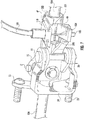
- FIG. 7 is a close-up of the view of FIG. 1 of the present invention with a slight change in orientation.
- FIG. 8 is a top view of the present invention.
- FIG. 9 is a lateral view of the present invention.
- FIG. 10 is a top view of the present invention, rotated about its anchor point.
- FIG. 11 is an exploded perspective view of the present invention.
- FIG. 12 is a lateral view of the present invention, rotated 180° with respect to FIG. 9 .
- FIG. 13 A is an end view of the present invention.
- FIG. 13 B is an end view of the present invention, rotated 180° with respect to FIG. 13 A.
- FIG. 14 is a bottom view of the present invention.
- FIG. 15 is an exploded perspective isolation of the Axial Lock.
- FIG. 16 is a perspective view of the present invention using an electronic actuator.
- FIG. 17 is a perspective view of the present invention using an electronic actuator, rotated 180° with respect to FIG. 16 .
- FIG. 15 shows the Axial Lock 800 that is embedded within the present invention.
- the Axial Lock 800 is comprised of a trunnion sleeve 450 , with three trunnions 44 , 45 , 451 and a flat feature 452 ; a two-piece housing 216 A, 216 B; a single coil spring 220 with tangs 598 on either end and an inner diameter 595 ; a notched sleeve 221 with a notch 596 and a release blade 46 , a bushing 223 with a ramp feature, and a notched bearing 218 with a notch 597 .
- the Axial Lock 800 fits over a rod 224 with an outer diameter 594 and an integral anchor hole 230 .
- a stopper 325 , a washer 225 , and a threaded fastener 226 are fastened to the end of the rod 224 , creating a stop for the Axial Lock 800 .
- the two-piece housing 216 A, 216 B captures the notched annular bearing 218 , notched sleeve 221 with a release blade 46 , coil spring 220 , bushing 223 , and trunnion sleeve 450 , causing all of the elements of the Axial Lock 800 to move, in unison, along the rod 224 .
- the inner diameter 595 of the coil spring 220 is slightly smaller than the outer diameter 594 of the rod 224 . This locks the Axial Lock 800 in place.
- One tang 598 of the coil spring 220 fits into the notch 597 of the notched bearing 218 and the other tang 598 of the coil spring 220 fits into the notch 596 of the notched sleeve 221 with release blade 46 .
- the release blade 46 When the release blade 46 is rotated through an acute angle, it slightly unwinds the coil spring 220 allowing the Axial Lock 800 to move, in unison, with respect to the rod 224 .
- FIG. 11 is an exploded view of the positioner mechanism using a linear adjusting lock 1 . Exterior portions of the Axial Lock 800 are still visible: the trunnion sleeve 450 and three trunnions 44 , 45 , 451 ; the release blade 46 , and the bushing 223 . The rod 224 with integral anchor hole 230 and the stop, composed of the stopper 325 , washer 225 , and threaded fastener 226 , are also visible.
- the positioner 1 uses a pivot pin 10 , a mounting bracket 34 , an upper pivot link 15 , and a lower pivot link 26 .
- the pivot links are identical planar members with two rounded ends 700 , 701 separated by a straight edge 702 .
- the upper pivot link 15 has an engagement notch 416 and three holes: 16 , 17 , 18 .
- the lower pivot link 26 has three holes: 27 , 28 , 29 .
- the upper pivot link has a center hole 18 and two outer holes 16 , 17 .
- the lower pivot link has a center hole 28 and two outer holes 27 , 29 .
- the engagement notch 416 is closer to one outer hole 17 than the other outer hole 16 .
- the holes 16 , 17 , 18 , 27 , 28 , 29 of the pivot links 15 , 26 are arranged substantially in a line running parallel to the straight edge 702 , although this in not a requirement of the invention.
- One pivot hole 27 is near one rounded end 701 .
- Another hole 29 is near the other rounded end 700 .
- the last pivot hole 28 is between the other two pivot holes 27 , 29 .
- the mounting bracket 34 has an upper pivot ear 39 with a hole 36 ; a lower pivot ear 38 with a hole 37 ; and two mounting tabs 40 through which threaded fasteners 35 fit.
- the pivot pin 10 has a head 11 , a shank 12 , and a nubbin 13 .
- the pivot pin 10 fits through the hole 36 in the upper pivot ear 39 of the mounting bracket 34 ; an upper bushing 14 ; a hole 17 of the upper pivot link 15 ; a hole 29 in the lower pivot link 26 ; a lower bushing 25 ; the hole 37 in the lower pivot ear 38 of the mounting bracket 34 ; and a washer 24 .
- Connector line 475 shows hole alignment, but not relative part orientation.
- a trunnion 45 on the trunnion sleeve 450 of the Axial Lock 800 fits through a bushing 19 and the center hole 18 of the upper pivot link 15 .
- a trunnion 451 on the trunnion sleeve 450 of the Axial Lock 800 fits through a bushing 30 and the center hole 28 of the lower pivot link 26 .
- a release anchor sleeve 47 is wrapped around the linear adjusting lock, aligning with the release blade 46 .
- a lock rivet 20 has a semi-cylindrical body 22 with a flattened surface 222 , an upper nubbin 21 , and a lower nubbin 23 .
- the upper nubbin 21 fits in a hole 16 of the upper pivot link 15 .
- the lower nubbin 23 fits in a hole 27 of the lower pivot link 26 .
- the semi-cylindrical body 22 of the lock rivet 20 is oriented so that the flattened surface 222 faces the flattened feature 452 of the trunnion sleeve 450 .
- a driven link 433 has an extension arm 32 , a pivot hole 33 , and an engagement tab 434 .
- the pivot hole 33 fits over a trunnion 44 on the trunnion sleeve 450 , and is locked with a retaining clip 31 .
- the driven link 433 can rotate about the trunnion 44 .
- the extension arm 32 contacts the release blade 46 .
- the engagement tab 434 contacts the engagement notch 416 .
- the integral anchor hole 230 of the rod 224 are connected to two retaining ears 43 with a hinge pin 41 .
- FIG. 1 shows the positioner mechanism using linear adjusting lock 1 .
- the integral anchor hole 230 of the rod 224 is connected to the rod anchor bracket 50 .
- the rod anchor bracket 50 has an attachment ear with hole 42 orthogonal to a pair of retaining ears 43 .
- the rod anchor bracket 50 attaches to the rod 224 at the integral anchor hole 230 with a hinge pin 41 . Also visible in FIG.
- the mounting bracket 34 and fasteners 35 are the mounting bracket 34 and fasteners 35 ; a trunnion 44 with retaining clip 31 ; a trunnion bushing 19 ; the upper 15 and lower pivot link 26 ; the pivot pin shank 12 and pivot pin head 11 ; the extension arm 32 of the driven link 433 ; the release blade 46 ; the release anchor sleeve 47 ; and stopper 325 and washer 225 .
- the release blade 46 of the linear adjusting lock is actuated by a release actuator 100 connected to a Bowden cable 101 .
- the inner cable 104 of the Bowden cable 101 moves the release blade 46 .
- the Bowden cable 101 is fixed to the release anchor sleeve 47 with a fitting 110 .
- FIG. 7 is a close-up of FIG. 1 , from a slightly different orientation. Similar to FIG. 1 , the rod 224 , the mounting bracket 34 and fasteners 35 ; the upper 15 and lower pivot link 26 ; and pivot pin head 11 are visible. Also visible in this view is the upper nubbin 21 of the lock rivet.
- the interaction of the release mechanism is illustrated in this drawing.
- the Bowden cable 101 meets the release anchor sleeve 47 at a fitting 110 .
- the Bowden cable termination nipple 105 rotates the notched sleeve 221 with release blade 46 , opening the spring 220 .
- This allows all of the parts 34 , 35 , 21 , 15 , 11 , 26 , 220 , 105 , 104 , 46 , 101 , 110 , 47 , 223 , 221 to move in unison with respect to the rod 224 .
- FIG. 5 shows the present invention 1 rotated 180° from FIG. 1 .
- the fastener 226 , washer 225 , and stopper 325 at the end of the rod 224 are visible.
- the attachment ear 42 of the rod anchor bracket is visible.
- the release actuator 100 , Bowden cable 101 and release anchor sleeve 47 are visible in this view, as is the Bowden cable 101 fitting 110 .
- the semi-cylindrical body 22 of the lock rivet, the two-piece housing 216 of the Axial Lock, notched bearing 218 , trunnion bushing 19 , pivot pin head 11 , mounting bracket mounting tab 40 , and mounting bracket fasteners 35 are all visible.
- a bump 80 in the mounting bracket, designed to provide rotational clearance, is also visible.
- FIG. 6 is a close-up of the view in FIG. 5 .
- important elements of the Axial Lock are visible: the trunnion sleeve 450 , the flat feature 452 of the trunnion sleeve, the two-piece housing 216 A, 216 B, a single coil spring 220 , the release blade 46 , a bushing with a ramp feature 223 , and a notched bearing 218 .
- the rod 224 , release anchor sleeve 47 , Bowden cable 101 , and the Bowden cable 101 fitting 110 are also visible in this view.
- FIGS. 8, 9, 12, and 14 are top, lateral, reverse lateral, and bottom views, respectively.
- the actuator 100 Bowden cable 101 , fitting 110 , stopper 325 , washer 225 , fastener 226 , pivot pin head 11 , lock rivet top nubbin 21 , upper pivot link 15 , mounting bracket bump 80 , mounting bracket upper ear 39 , release anchor sleeve 47 , two-piece housing 216 , mounting bracket mounting tab 40 , mounting bracket fastener 35 , rod 224 , rod anchor bracket attachment ear 42 , retaining ear 43 , and hinge pin 41 are visible.
- the actuator 100 Bowden cable 101 , inner cable 104 , termination nipple 105 , fitting 110 , stopper 325 , washer 225 , fastener 226 , pivot pin head 11 , pivot pin shank 12 , upper pivot link 15 , lower pivot link 26 , mounting bracket 34 , release anchor sleeve 47 , release blade 46 , mounting bracket fastener 35 , rod 224 , rod anchor bracket attachment ear 42 , retaining ear 43 , hinge pin 41 , the extension arm 32 of the driven link 433 , engagement tab 434 , and retaining clip 31 are visible.
- FIG. 12 Bowden cable 101 , termination nipple 105 , fitting 110 , stopper 325 , washer 225 , fastener 226 , release anchor sleeve 47 , rod 224 , rod anchor bracket attachment ear 42 , mounting bracket fastener 35 , two-piece housing 216 , and coil spring 220 are visible.
- the actuator 100 Bowden cable 101 , termination nipple 105 , fitting 110 , stopper 325 , washer 225 , two-piece housing 216 , release blade 46 , release anchor sleeve 47 , mounting bracket fastener 35 , mounting bracket 34 , mounting bracket mounting tab 40 , lower pivot link 26 , rod 224 , rod anchor bracket attachment ear 42 , hinge pin 41 , and the extension arm 32 are visible.
- FIGS. 13A and 13B are end views of the present invention 1 .
- the rod anchor bracket attachment ear 42 , mounting bracket 34 , mounting bracket mounting tabs 40 , bracket fasteners 35 , Bowden cable 101 , fitting 110 , and lock rivet 20 are visible.
- the stopper washer 225 , fastener 226 , the rod anchor bracket attachment ear 42 , mounting bracket mounting tabs 40 , bracket fasteners 35 , Bowden cable 101 , fitting 110 , and lock rivet shank 22 are visible.
- FIG. 10 shows the range of motion of the present invention 1 , 1 ′, 1 ′′, swinging 201 from a closed position 1 ′′ to an intermediate position 1 ′; and swinging further 200 from an intermediate position 1 ′ to a fully opened position 1 A re-positioning aggregation 599 moves with respect to the rod 224 .
- the re-positioning aggregation 599 is comprised of a trunnion sleeve 450 , with three trunnions 44 , 45 , 451 and a flat feature 452 ; a two-piece housing 216 A, 216 B; a single coil spring 220 ; a notched sleeve 221 with release blade 46 ; a bushing with a ramp feature 223 ; a notched bearing 218 ; a stopper 325 ; the pivot pin 10 ; the mounting bracket 34 ; the upper pivot link 15 ; the lower pivot link 26 ; the lock rivet 20 ; the driven link 433 and retaining clip 31 ; and associated bushings, washers, and fasteners 24 , 25 , 30 , 19 , 14 , 35 .
- the re-positioning aggregation 599 When the present invention 1 ′′ is the closed position, the re-positioning aggregation 599 is closest to the rod anchor attachment ear 42 . As the present invention 1 ′ is opened 200 to an intermediate position, the re-positioning aggregation 599 is positioned further away from rod anchor attachment ear 42 , rotating about the hinge 41 . When the present invention 1 is in its fully opened position, the re-positioning aggregation 599 is furthest from the rod anchor attachment ear 42 , rotating about the hinge 41
- FIGS. 2-4 show the present invention 1 , in situ, being used as a positioner for a car door.
- the positioner would prevent the door from moving outwards without the release lever being pulled, either inside or outside the car door.
- Such an application would prevent the door from moving, if the wind or gravity pulled the door out of the person's hand.
- the present invention 1 a positioner mechanism using a linear adjusting lock 1 , is installed on a car door shell 500 .
- the hinge surface 502 is orthogonal to the inner sheet metal surface 503 and the short surface 506 .
- the present invention is installed on the hinge surface 502 very near the edge 510 .
- the re-positioning aggregation 599 and stopper 325 and washer 225 are inside the shell, as is a substantial portion of the rod 224 , when the door in in the closed position.
- the rod anchor attachment ear 42 is attached to the car body.
- the mounting bracket 34 mounts the re-positioning aggregation 599 to the door shell 500 . When the door shell 500 is fully opened, the stopper 325 hits the bushing 223 of the linear adjusting lock 800 , stopping motion.
- the actuator 100 attached to the handle pulls the inner cable 104 , causing the release blade 46 to rotate.
- the coil spring 220 situated between the notched sleeve 221 and the notched bearing 218 has a tang 598 at either end. One tang 598 fits into the notch 596 of the notched sleeve 221 and the other tang 598 fits into the notch 597 of the notched bearing 218 .
- the release blade 46 rotates, it causes the coil spring 220 to uncoil slightly, increasing its inner diameter 595 , so that the coil spring 220 inner diameter 595 is larger than the rod 224 outer diameter 594 .
- the coil spring 220 When the coil spring 220 is slightly uncoiled, it releases the rod 224 allowing the rod 224 to slide through the re-positioning aggregation 599 .
- the actuator 100 releases and the coil spring 220 recoils, grabbing the rod 224 and preventing it from moving relative to the re-positioning aggregation 599 .
- the present invention 1 has an over-ride mechanism to the linear adjusting lock 800 .
- pressure is put on the outside of the door shell 500 , to close the door, it causes the upper pivot link 15 and the lower pivot link 26 to rotate slightly with respect to the linear adjusting lock 800 .
- the engagement notch 416 of the upper pivot link 15 is in contact with the engagement tab 434 of the drive link 433 .
- the engagement notch 416 applies force to the engagement tab 434 , rotating the drive link 433 around the pivot hole 33 .
- the extension arm 32 rotates the blade 46 through an acute angle, releasing the coil spring 220 and allowing the rod 224 to slide through the re-positioning aggregation 599 . In this way, pressure on the exterior of the car door, applied to close the car door, overcomes the linear adjusting lock 800 , allowing the door to close.
- the trunnions 45 , 451 of the trunnion sleeve 450 is the axis of rotation about which the upper pivot link 15 and the lower pivot link 26 rotate.
- the lock rivet 20 keeps the upper pivot link 15 and the lower pivot link 26 in synch while rotating.
- the lock rivet 20 also, allows rotation of the upper pivot link 15 and the lower pivot link 26 in one direction and prevents rotation in the other direction, because of the engagement of the flattened surface 222 to the flattened feature 452 of the trunnion sleeve 450 .
- the linear adjusting lock without an over-ride mechanism, can prevent motion in either direction without the use of the door handle.
- FIG. 3 shows a close-up of the present invention 1 in situ in a door shell 500 .
- a cut-away 600 shows the re-positioning aggregation 599 , even though it would normally be behind the sheet metal surfaces 503 , 502 .
- the present invention 1 is very close to the edge 510 between the inner surface 503 and the hinge surface 502 .
- FIG. 3 shows the hinge surface 502 , the edge 510 , the cross-member 504 , the inner edge 501 , the short surface 506 , the rod anchor attachment ear 42 , the rod 224 and the washer 225 .
- FIG. 4 is an end view of the present invention 1 in the door shell 500 .
- the mounting ears 40 , fasteners 35 , and rod anchor attachment ear 42 are visible through a cut-away 601 .
- FIGS. 16 and 17 show an alternative embodiment of the present invention 1 using an electronic actuator 306 .
- This embodiment uses an electronic solenoid or electronic linear actuator 301 to retract the cable 104 .
- the electronic solenoid or electronic linear actuator 301 is fed by two power wires 302 , 303 .
- the wires 302 , 303 terminate on the top surface 304 of the electronic solenoid or electronic linear actuator 301 , although the wires 302 , 303 can conceivably terminate anywhere on the electronic solenoid or electronic linear actuator 301 .
- the electronic solenoid or electronic linear actuator is fixed to the release anchor sleeve 47 . Otherwise, the over-ride mechanism and the linear adjusting lock 800 work the same as the previously described embodiment.
Landscapes
- Engineering & Computer Science (AREA)
- Mechanical Engineering (AREA)
- Lock And Its Accessories (AREA)
Abstract
The present invention is a positioning mechanism device to prevent the motion of one surface with respect to a second surface, in one direction. The positioning mechanism uses a linear adjusting lock, an actuator, and an over-ride mechanism. The linear adjusting lock uses a coil spring to hold a rod in place. When firmly coiled, the coil spring is able to grip a smooth rod and prevent axial motion. When the coil spring is uncoiled, slightly, it releases its grip on the smooth rod, allowing axial motion. The positioner mechanism uses an actuator and release blade to release the coil spring. Additionally, the over-ride mechanism can be used to release the release blade in one direction without use of the actuator. When the coil spring is released by either the actuator or over-ride mechanism the two surfaces can be re-positioned relative to one another.
Description
This invention relates to the classification of miscellaneous hardware, and to one or more sub-classifications under spring-aided closure checks. Specifically, this invention is positioner mechanism using a linear adjusting lock.
There are many situations in which an object needs to be moved into a position, and have that position maintained. Typically, the object to be moved is a large, hinged surface that needs to be re-positioned with respect to the structure to which it is hinged. Examples include car doors, trunks and hoods, as well as oven doors, dishwasher doors, and other large residential and commercial appliances and machinery. When such a surface is moved to a new position, it is often advantageous to lock it into position in either one or two directions. In other words, its advantageous, many times, to either prevent it from opening further or prevent it from shutting.
A car door provides an exemplary illustration of this problem. A car door is a surface which one would wish to remain in the position to which it was opened. With a few notable exceptions, the standard configuration of a motor vehicle cabin, and the doors on it, has remained relatively unchanged for over 100 years. Most motor vehicles have either two or four doors, excluding the trunk or rear hatchback. A conventional door is hinged at its forward edge, allowing its rearward edge to rotate outward from the vehicle side. Most vehicles have at least two conventional doors; one on the front driver-side and one on the front passenger-side. A vehicle may have more than two conventional doors. Typically, the cabin is accessed through an even number of doors placed symmetrically along the two sides of the vehicle, although some minivans and full-sized vans may have a single sliding door with or without an opposing conventional door. The utility of vehicle doors has changed dramatically over the last 100 years, as windows, window regulators, loudspeakers, electronic locks, sound dampening material, structural cross-members, and, of course, sliding van doors have been added.
Although vehicle doors may have electronic locks and other creature comforts, most articulating or conventional door mechanisms are largely manual with respect to door opening and closing, relying on the driver or other vehicle occupant to move the conventional door to the correct position for ingress and egress. Positioning a conventional door is a ubiquitous part of vehicle operation.
However, positioning the conventional door of a vehicle is often complicated in high wind conditions, or when the vehicle is parked on a hill. In high wind conditions, the wind can often pull a conventional door out of the user's hand. This can lead to damage to adjacent vehicles or structures; damage to the door surface, structure, or hinges; or injury to individuals in the path of the wind-blown door. Likewise, when parked on a hill, gravity can complicate ingress and egress, pulling the door out of the occupant's hand, and causing the damage listed above.
Currently, there is not a cheap and easy solution to this problem. The prior art is void of conventional door positioners designed to prevent an unexpected force, caused by the wind or gravity, from pulling the door out of the user's hand. As always with automotive hardware, considerations of weight, cost, and reliability are paramount.
This summary is intended to disclose the present invention, a positioner mechanism using a linear adjusting lock. The embodiments and descriptions are used to illustrate the invention and its utility, and are not intended to limit the invention or its use.
The present invention relates to using an over-ride mechanism in conjunction with a mechanical linear adjusting lock device, in order to prevent unwanted motion in one direction for a large, hinged surface. The embodiment discussed herein is an over-ride mechanism used with a single-spring linear adjusting lock in a vehicle door application, but the invention will work with a multi-spring linear adjusting lock of similar construction, as well with other large hinged surfaces. The linear adjusting lock comprises a rod, a notched annular bearing, a notched sleeve with a release blade, a housing, a coil spring, and a bushing. A cylinder with protrusions (hereinafter, the cylinder protrusions will be referred to as “trunnions”, and the cylinder, itself, will be referred to as a “trunnion sleeve”) mates the linear adjusting lock with an over-ride mechanism. The notched annular bearing, notched sleeve with a release blade, housing, coil spring, bushing, and trunnion sleeve all fit over the rod.
In this embodiment, a two-piece housing is used. The two-piece housing captures the notched annular bearing, notched sleeve with a release blade, coil spring, bushing, and trunnion sleeve, causing all of the elements to move in unison along the rod. For the sake of brevity, in this application, the notched annular bearing, notched sleeve with release blade, two-piece housing, coil spring, bushing, and trunnion sleeve are called the Axial Lock.
The rod has a rod hole at one end and a smooth, cylindrical opposing end over which the Axial Lock fits. The rod hole is connected to an anchor point. The trunnion sleeve's protruding trunnions mate with mating holes in the over-ride mechanism. The positioning mechanism, comprised of the Axial Lock and over-ride mechanism, has a mounting bracket. The invention will work with any housing wherein the linear adjusting lock is of similar construction.
The inner diameter of the coil spring is slightly smaller than the outer diameter of the rod. When firmly coiled, the coil spring is able to grip the smooth rod and prevent axial motion of the Axial Lock along the rod. When the coil spring is uncoiled, slightly, it releases its grip on the smooth rod, allowing axial motion of the Axial Lock along the length of the rod.
The coil spring is made of spring steel, or similar spring material, and has two protruding tangs. In this embodiment, the two protruding tangs are radially disposed at approximately a 90° angle from one another, although the radial angle between the tangs is largely immaterial. The notched sleeve is a cylinder with a flat blade extending orthogonally from its outer surface. The interior of the notched sleeve facing the coil spring has a ramp feature. The ramp feature is achieved by beveling the inner surface of the sleeve towards the cylinder end. The sleeve has a notch that mates with one of the tangs of the coil spring. The annular bearing also has a notch and a ramp feature. The notch of the annular bearing mates with the other tang of the coil spring.
When a tensile load is applied to the Axial Lock, the ramp feature inside the bearing causes the coil spring coils to tilt and grip the rod in proportion to the load. When a compressive load is applied to the Axial Lock, the ramp feature inside the sleeve with release blade causes the coil spring coils to tilt in the opposite orientation and grip the rod in proportion to the load. The Axial Lock device is unlocked by applying force to the sleeve blade, until the sleeve blade rotates through an acute angle. The coil spring is unwound, slightly, which causes the inner diameter of the coil spring to increase until there is a clearance between the coil spring and the rod. In this condition, the Axial Lock is free to move axially along the length of the rod to provide a re-positioning function. This allows the relative distance between the anchor and the mounting bracket to be adjusted by sliding the Axial Lock along the length of the rod. The Axial Lock is re-locked to the rod, in any position, by removing the force on the sleeve blade.
The over-ride system interoperates with the Axial Lock. The over-ride mechanism is comprised of an upper pivot link, a lower pivot link, a pivot pin, a lock rivet, a driven link, and assorted bushings, retaining clips, and fasteners. The over-ride mechanism is attached to the mounting bracket. The upper pivot link and the lower pivot link are identical in construction: The pivot links are constructed from steel or another durable material. The pivot links are largely planar with two rounded ends and a straight edge. The upper and lower pivot links each have three holes, spaced substantially in a line along the planar surface of the pivot links. The center hole in the upper pivot link mates with a trunnion on the trunnion sleeve. The center hole in the lower pivot link mates with another trunnion on the trunnion sleeve. The trunnions with which the upper pivot link and lower pivot link mate are opposed 180° from one another on the trunnion sleeve. The trunnions on the trunnion sleeve act as an axis of rotation for the upper and lower pivot link.
The mounting bracket has two pivot ears and two mounting ears, which are orthogonal to the pivot ears. The pivot pin passes through a hole in the upper pivot ear of the mounting bracket, a hole in the upper pivot link, a hole in the lower pivot link, and a hole in the lower pivot ear in the mounting bracket. The pivot pin locks the upper pivot link and lower pivot link together, so that they share the same rotation. The pivot pin also connects the mounting bracket to the pivot links. The upper pivot link and lower pivot link can rotate about the axis formed by their respective trunnions.
The driven link mates with a trunnion on the trunnion sleeve, which is orthogonal to the trunnions holding the upper and lower pivot links. The driven link can rotate about its trunnion, and is held against the trunnion by a retaining clip. The driven link has an engagement tab and an extension arm. The engagement tab is in contact with an engagement notch in the upper pivot link. The extension arm is in contact with the release blade. When the upper pivot link pivots, it exerts force on the engagement tab of the driven link, which causes the driven link to rotate about its trunnion. This causes the extension arm of the pivot link to apply force to the release blade and rotate it through a small acute angle, unlocking the Axial Lock. In this way, a small rotation of the pivot links unlocks the Axial Lock.
The lock rivet connects to a third hole in the upper pivot link and the lower pivot link. The lock rivet is semi-cylindrical with a flattened face. The flattened face engages with a flattened feature on the trunnion sleeve. The flattened face and flattened feature interact to prevent counter-rotation. In other words, the lock rivet functions to prevent the over-ride mechanism from rotating so that the engagement notch of the upper pivot link moves away from the engagement tab of the driven link.
In an automotive application, the positioner mechanism using a linear adjusting lock can be used to prevent the car door from traveling past desired position if the door is pulled from the user's hand due to high-wind conditions or gravity. In this application, the interior and exterior handles are connected to an actuator. The actuator can be a simple mechanical connection, or it can be an electrical actuator. When the user uses the door release handles the actuator activates the release blade and the car door is free to swing in either rotational direction. When the user releases the door handle, the actuator retracts and the release blade returns to its nominal position, causing the Axial Lock to lock the door from rotating further open. The lock rivet locks when the door is caught by the wind, preventing the over-ride mechanism from engaging. When the user pushes the door from the outside, or pulls from the inside, to close the door, the over-ride mechanism of the positioner mechanism rotates the release blade through an acute angle, unlocking the Axial Lock and allowing the door to close.
The present invention is illustrated with 17 drawings on 17 sheets.
The following descriptions are not meant to limit the invention, but rather to add to the summary of invention, and illustrate the present invention, by offering and illustrating various embodiments of the present invention, a positioner mechanism using linear adjusting lock. While embodiments of the invention are illustrated and described, the embodiments herein do not represent all possible forms of the invention. Rather, the descriptions, illustrations, and embodiments are intended to teach and inform without limiting the scope of the invention.
The inner diameter 595 of the coil spring 220 is slightly smaller than the outer diameter 594 of the rod 224. This locks the Axial Lock 800 in place. One tang 598 of the coil spring 220 fits into the notch 597 of the notched bearing 218 and the other tang 598 of the coil spring 220 fits into the notch 596 of the notched sleeve 221 with release blade 46. When the release blade 46 is rotated through an acute angle, it slightly unwinds the coil spring 220 allowing the Axial Lock 800 to move, in unison, with respect to the rod 224.
The positioner 1 uses a pivot pin 10, a mounting bracket 34, an upper pivot link 15, and a lower pivot link 26. The pivot links are identical planar members with two rounded ends 700, 701 separated by a straight edge 702. The upper pivot link 15 has an engagement notch 416 and three holes: 16, 17, 18. The lower pivot link 26 has three holes: 27, 28, 29. The upper pivot link has a center hole 18 and two outer holes 16, 17. The lower pivot link has a center hole 28 and two outer holes 27, 29. The engagement notch 416 is closer to one outer hole 17 than the other outer hole 16. In this embodiment, the holes 16, 17, 18, 27, 28, 29 of the pivot links 15, 26 are arranged substantially in a line running parallel to the straight edge 702, although this in not a requirement of the invention. One pivot hole 27 is near one rounded end 701. Another hole 29 is near the other rounded end 700. The last pivot hole 28 is between the other two pivot holes 27, 29.
The mounting bracket 34 has an upper pivot ear 39 with a hole 36; a lower pivot ear 38 with a hole 37; and two mounting tabs 40 through which threaded fasteners 35 fit. The pivot pin 10 has a head 11, a shank 12, and a nubbin 13. The pivot pin 10 fits through the hole 36 in the upper pivot ear 39 of the mounting bracket 34; an upper bushing 14; a hole 17 of the upper pivot link 15; a hole 29 in the lower pivot link 26; a lower bushing 25; the hole 37 in the lower pivot ear 38 of the mounting bracket 34; and a washer 24. Connector line 475 shows hole alignment, but not relative part orientation.
A trunnion 45 on the trunnion sleeve 450 of the Axial Lock 800 fits through a bushing 19 and the center hole 18 of the upper pivot link 15. A trunnion 451 on the trunnion sleeve 450 of the Axial Lock 800 fits through a bushing 30 and the center hole 28 of the lower pivot link 26.
A release anchor sleeve 47 is wrapped around the linear adjusting lock, aligning with the release blade 46.
A lock rivet 20 has a semi-cylindrical body 22 with a flattened surface 222, an upper nubbin 21, and a lower nubbin 23. The upper nubbin 21 fits in a hole 16 of the upper pivot link 15. The lower nubbin 23 fits in a hole 27 of the lower pivot link 26. The semi-cylindrical body 22 of the lock rivet 20 is oriented so that the flattened surface 222 faces the flattened feature 452 of the trunnion sleeve 450.
A driven link 433 has an extension arm 32, a pivot hole 33, and an engagement tab 434. The pivot hole 33 fits over a trunnion 44 on the trunnion sleeve 450, and is locked with a retaining clip 31. The driven link 433 can rotate about the trunnion 44. The extension arm 32 contacts the release blade 46. The engagement tab 434 contacts the engagement notch 416.
The integral anchor hole 230 of the rod 224 are connected to two retaining ears 43 with a hinge pin 41. There is an attachment ear 42 orthogonal to the two retaining ears 43.
The release blade 46 of the linear adjusting lock is actuated by a release actuator 100 connected to a Bowden cable 101. The inner cable 104 of the Bowden cable 101 moves the release blade 46. The Bowden cable 101 is fixed to the release anchor sleeve 47 with a fitting 110.
The interaction of the release mechanism is illustrated in this drawing. The Bowden cable 101 meets the release anchor sleeve 47 at a fitting 110. When the inner cable 104 is pulled, the Bowden cable termination nipple 105 rotates the notched sleeve 221 with release blade 46, opening the spring 220. This allows all of the parts 34, 35, 21, 15, 11, 26, 220, 105, 104, 46, 101, 110, 47, 223, 221 to move in unison with respect to the rod 224.
In the lateral view, FIG. 9 , the actuator 100, Bowden cable 101, inner cable 104, termination nipple 105, fitting 110, stopper 325, washer 225, fastener 226, pivot pin head 11, pivot pin shank 12, upper pivot link 15, lower pivot link 26, mounting bracket 34, release anchor sleeve 47, release blade 46, mounting bracket fastener 35, rod 224, rod anchor bracket attachment ear 42, retaining ear 43, hinge pin 41, the extension arm 32 of the driven link 433, engagement tab 434, and retaining clip 31 are visible.
In the reverse lateral view, FIG. 12 , Bowden cable 101, termination nipple 105, fitting 110, stopper 325, washer 225, fastener 226, release anchor sleeve 47, rod 224, rod anchor bracket attachment ear 42, mounting bracket fastener 35, two-piece housing 216, and coil spring 220 are visible.
In the bottom view, FIG. 14 , the actuator 100, Bowden cable 101, termination nipple 105, fitting 110, stopper 325, washer 225, two-piece housing 216, release blade 46, release anchor sleeve 47, mounting bracket fastener 35, mounting bracket 34, mounting bracket mounting tab 40, lower pivot link 26, rod 224, rod anchor bracket attachment ear 42, hinge pin 41, and the extension arm 32 are visible.
When the present invention 1″ is the closed position, the re-positioning aggregation 599 is closest to the rod anchor attachment ear 42. As the present invention 1′ is opened 200 to an intermediate position, the re-positioning aggregation 599 is positioned further away from rod anchor attachment ear 42, rotating about the hinge 41. When the present invention 1 is in its fully opened position, the re-positioning aggregation 599 is furthest from the rod anchor attachment ear 42, rotating about the hinge 41
In FIG. 2 , the present invention 1, a positioner mechanism using a linear adjusting lock 1, is installed on a car door shell 500. There is an inner sheet metal surface 503, hinge surface 502, an edge 510 between the inner surface 503 and the hinge surface 502, a plurality of cut-outs 505, a cross-member 504, an inner edge 501, and short surface 506. The hinge surface 502 is orthogonal to the inner sheet metal surface 503 and the short surface 506. The present invention is installed on the hinge surface 502 very near the edge 510. The re-positioning aggregation 599 and stopper 325 and washer 225 are inside the shell, as is a substantial portion of the rod 224, when the door in in the closed position. The rod anchor attachment ear 42 is attached to the car body. The mounting bracket 34 mounts the re-positioning aggregation 599 to the door shell 500. When the door shell 500 is fully opened, the stopper 325 hits the bushing 223 of the linear adjusting lock 800, stopping motion.
When the door is opened using either the interior or exterior handle (not shown), the actuator 100 attached to the handle pulls the inner cable 104, causing the release blade 46 to rotate. The coil spring 220 situated between the notched sleeve 221 and the notched bearing 218 has a tang 598 at either end. One tang 598 fits into the notch 596 of the notched sleeve 221 and the other tang 598 fits into the notch 597 of the notched bearing 218. When the release blade 46 rotates, it causes the coil spring 220 to uncoil slightly, increasing its inner diameter 595, so that the coil spring 220 inner diameter 595 is larger than the rod 224 outer diameter 594. When the coil spring 220 is slightly uncoiled, it releases the rod 224 allowing the rod 224 to slide through the re-positioning aggregation 599. When the door handle is released, the actuator 100 releases and the coil spring 220 recoils, grabbing the rod 224 and preventing it from moving relative to the re-positioning aggregation 599.
The present invention 1 has an over-ride mechanism to the linear adjusting lock 800. When pressure is put on the outside of the door shell 500, to close the door, it causes the upper pivot link 15 and the lower pivot link 26 to rotate slightly with respect to the linear adjusting lock 800. The engagement notch 416 of the upper pivot link 15 is in contact with the engagement tab 434 of the drive link 433. When the upper pivot link 15 pivots, the engagement notch 416 applies force to the engagement tab 434, rotating the drive link 433 around the pivot hole 33. The extension arm 32 rotates the blade 46 through an acute angle, releasing the coil spring 220 and allowing the rod 224 to slide through the re-positioning aggregation 599. In this way, pressure on the exterior of the car door, applied to close the car door, overcomes the linear adjusting lock 800, allowing the door to close.
The trunnions 45, 451 of the trunnion sleeve 450 is the axis of rotation about which the upper pivot link 15 and the lower pivot link 26 rotate. The lock rivet 20 keeps the upper pivot link 15 and the lower pivot link 26 in synch while rotating. The lock rivet 20, also, allows rotation of the upper pivot link 15 and the lower pivot link 26 in one direction and prevents rotation in the other direction, because of the engagement of the flattened surface 222 to the flattened feature 452 of the trunnion sleeve 450. In other applications, the linear adjusting lock, without an over-ride mechanism, can prevent motion in either direction without the use of the door handle.
Claims (20)
1. A positioning mechanism device to set a position between a first surface and a second surface comprising
a linear adjusting lock comprised of
a rod with an outer diameter and anchor hole,
at least one coil spring with an inner diameter, and a tang at either end,
an annular, notched sleeve and a release blade, and
an annular notched bearing,
wherein one tang of at least one coil spring mates with the notch in the annular, notched sleeve, and wherein the other tang of at least one coil spring mates with the notch in the annular notched bearing;
wherein the inner diameter of the spring is smaller than the outer diameter of the rod, thereby locking the rod into position relative to the spring; and
wherein the release blade, when rotated through an acute angle, slightly uncoils the spring, unlocking the rod's relative position with respect to the spring;
an actuator attached to the release blade; and
an over-ride mechanism;
wherein the rod anchor hole is attached to one of the two surfaces and the over-ride mechanism is attached to the other of the two surfaces;
wherein, when activated, the actuator, independent of the over-ride mechanism, can rotate the release blade through an acute angle, unlocking the rod's relative position with respect to the spring; and
wherein the over-ride mechanism, independent of the actuator, can rotate the release blade through an acute angle, unlocking the rod's relative position with respect to the spring.
2. The positioner mechanism device of claim 1 , wherein the over-ride mechanism is comprised of
an upper and lower pivot link,
a pivot pin, having a head and a shank,
a semi-cylindrical lock rivet possessing a flattened side,
and a driven link;
wherein each pivot link is planar, each pivot link contains at least three holes, and the upper pivot link has an edge notch;
wherein the three holes of each pivot link are arranged so that there is a center hole and two outer holes on each pivot link, and wherein the edge notch of the upper pivot link is closer to one outer hole than the other outer hole; and
wherein the driven link has a tab, a pivot hole, and an extension arm.
3. The positioner mechanism device of claim 2 , wherein the over-ride mechanism is attached to the linear adjusting lock with an annular trunnion sleeve.
4. The positioner mechanism device of claim 3 , wherein the annular trunnion sleeve has a cylindrical surface, at least three orthogonal trunnions, and a flattened feature extending from the cylindrical surface.
5. The positioner mechanism device of claim 4 , further comprising a mounting bracket to mount the over-ride mechanism to a surface.
6. The positioner mechanism device of claim 5 , wherein the mounting bracket is comprised of
at least two mounting tabs,
an upper pivot ear, and
a lower pivot ear;
wherein each tab and each pivot ear has a hole.
7. The positioner mechanism device of claim 6 , wherein, in order, the pivot pin passes through,
the hole in the upper pivot ear of the mounting bracket,
the outer hole of the upper pivot link that is closest to the edge notch,
an outer hole of the lower pivot link,
and the hole in the lower pivot ear of the mounting bracket.
8. The positioner mechanism device of claim 7 , wherein
a first trunnion of the trunnion sleeve fits through the center hole of the upper pivot link,
a second trunnion of the trunnion sleeve, disposed radially about the cylindrical surface of the trunnion sleeve 180° from the first trunnion, fits through the center hole of the lower pivot link, and
a third trunnion of the trunnion sleeve, disposed radially about the cylindrical surface of the trunnion sleeve 90° from both the first and second trunnions, fits through the pivot hole of the driven link.
9. The positioner mechanism of claim 8 , wherein
the flattened feature of the trunnion sleeve is disposed, radially, 90° from both the first trunnion and second trunnion, and 180° from the third trunnion;
the lock rivet inserts through an outer hole of the upper pivot link and an outer hole of the lower pivot link, and
the flattened side of the lock rivet faces the flattened feature of the trunnion sleeve.
10. The positioner mechanism device of claim 9 , wherein, when activated, the actuator allows the second surface to be re-positioned relative to the first surface.
11. The positioner mechanism device of claim 10 , wherein the actuator is an electrical actuator.
12. The positioner mechanism device of claim 10 , wherein the actuator is a mechanical actuator.
13. The positioner mechanism device of claim 11 , wherein
the rod anchor hole is attached to the first surface and the mounting bracket of the over-ride mechanism is attached to the second surface;
wherein a compressive force pushing the second surface towards the first surface causes the over-ride mechanism to activate by rotating the upper and lower pivot link about their respective trunnions, causing the notched edge to apply a force to the driven link tab, causing the driven link to rotate about the pivot hole, forcing the extension arm of the driven link to rotate the release blade through an acute angle, releasing the linear adjusting lock; and
wherein a tensile force pulling the second surface away from the first surface causes the flattened side of the lock rivet to interact with the flattened feature of the trunnion sleeve, preventing the over-ride mechanism from moving, allowing the linear adjusting lock to remain locked.
14. The positioner mechanism device of claim 11 , wherein
the rod anchor hole is attached to the first surface and the mounting bracket of the over-ride mechanism is attached to the second surface;
wherein a tensile force pulling the second surface away from the first surface causes the over-ride mechanism to activate by rotating the upper and lower pivot link about their respective trunnions, causing the notched edge to apply a force to the driven link tab, causing the driven link to rotate about the pivot hole, forcing the extension arm of the driven link to rotate the release blade through an acute angle, releasing the linear adjusting lock; and
wherein a compressive force pushing the second surface towards the first surface causes the flattened side of the lock rivet to interact with the flattened feature of the trunnion sleeve, preventing the over-ride mechanism from moving, allowing the linear adjusting lock to remain locked.
15. The positioner mechanism device of claim 11 , wherein
the rod anchor hole is attached to the second surface and the mounting bracket of the over-ride mechanism is attached to the first surface;
wherein a compressive force pushing the second surface towards the first surface causes the over-ride mechanism to activate by rotating the upper and lower pivot link about their respective trunnions, causing the notched edge to apply a force to the driven link tab, causing the driven link to rotate about the pivot hole, causing the extension arm of the driven link to rotate the release blade through an acute angle, releasing the linear adjusting lock; and
wherein a tensile force pulling the second surface away from the first surface causes the flattened side of the lock rivet to interact with the flattened feature of the trunnion sleeve, preventing the over-ride mechanism from moving, allowing the linear adjusting lock to remain locked.
16. The positioner mechanism device of claim 11 , wherein
the rod anchor hole is attached to the second surface and the mounting bracket of the over-ride mechanism is attached to the first surface;
wherein a tensile force pulling the second surface away from the first surface causes the over-ride mechanism to activate by rotating the upper and lower pivot link about their respective trunnions, causing the notched edge to apply a force to the driven link tab, causing the driven link to rotate about the pivot hole, forcing the extension arm of the driven link to rotate the release blade through an acute angle, releasing the linear adjusting lock; and
wherein a compressive force pushing the second surface towards the first surface causes the flattened side of the lock rivet to interact with the flattened feature of the trunnion sleeve, preventing the over-ride mechanism from moving, allowing the linear adjusting lock to remain locked.
17. The positioner mechanism device of claim 12 , wherein
the rod anchor hole is attached to the first surface and the mounting bracket of the over-ride mechanism is attached to the second surface;
wherein a compressive force pushing the second surface towards the first surface causes the over-ride mechanism to activate by rotating the upper and lower pivot link about their respective trunnions, causing the notched edge to apply a force to the driven link tab, causing the driven link to rotate about the pivot hole, causing the extension arm of the driven link to rotate the release blade through an acute angle, releasing the linear adjusting lock; and
wherein a tensile force pulling the second surface away from the first surface causes the flattened side of the lock rivet to interact with the flattened feature of the trunnion sleeve, preventing the over-ride mechanism from moving, allowing the linear adjusting lock to remain locked.
18. The positioner mechanism device of claim 12 , wherein
the rod anchor hole is attached to the first surface and the mounting bracket of the over-ride mechanism is attached to the second surface;
wherein a tensile force pulling the second surface away from the first surface causes the over-ride mechanism to activate by rotating the upper and lower pivot link about their respective trunnions, causing the notched edge to apply a force to the driven link tab, causing the driven link to rotate about the pivot hole, causing the extension arm of the driven link to rotate the release blade through an acute angle, releasing the linear adjusting lock; and
wherein a compressive force pushing the second surface towards the first surface causes the flattened side of the lock rivet to interact with the flattened feature of the trunnion sleeve, preventing the over-ride mechanism from moving, allowing the linear adjusting lock to remain locked.
19. The positioner mechanism device of claim 12 , wherein
the rod anchor hole is attached to the second surface and the mounting bracket of the over-ride mechanism is attached to the first surface;
wherein a compressive force pushing the second surface towards the first surface causes the over-ride mechanism to activate by rotating the upper and lower pivot link about their respective trunnions, causing the notched edge to apply a force to the driven link tab, causing the driven link to rotate about the pivot hole, causing the extension arm of the driven link to rotate the release blade through an acute angle, releasing the linear adjusting lock; and
wherein a tensile force pulling the second surface away from the first surface causes the flattened side of the lock rivet to interact with the flattened feature of the trunnion sleeve, preventing the over-ride mechanism from moving, allowing the linear adjusting lock to remain locked.
20. The positioner mechanism device of claim 12 , wherein
the rod anchor hole is attached to the second surface and the mounting bracket of the over-ride mechanism is attached to the first surface;
wherein a tensile force pulling the second surface away from the first surface causes the over-ride mechanism to activate by rotating the upper and lower pivot link about their respective trunnions, causing the notched edge to apply a force to the driven link tab, causing the driven link to rotate about the pivot hole, causing the extension arm of the driven link to rotate the release blade through an acute angle, releasing the linear adjusting lock; and
wherein a compressive force pushing the second surface towards the first surface causes the flattened side of the lock rivet to interact with the flattened feature of the trunnion sleeve, preventing the over-ride mechanism from moving, allowing the linear adjusting lock to remain locked.
Priority Applications (1)
| Application Number | Priority Date | Filing Date | Title |
|---|---|---|---|
| US15/642,385 US10815708B2 (en) | 2017-07-06 | 2017-07-06 | Positioner mechanism using linear adjusting lock |
Applications Claiming Priority (1)
| Application Number | Priority Date | Filing Date | Title |
|---|---|---|---|
| US15/642,385 US10815708B2 (en) | 2017-07-06 | 2017-07-06 | Positioner mechanism using linear adjusting lock |
Publications (2)
| Publication Number | Publication Date |
|---|---|
| US20190010740A1 US20190010740A1 (en) | 2019-01-10 |
| US10815708B2 true US10815708B2 (en) | 2020-10-27 |
Family
ID=64904106
Family Applications (1)
| Application Number | Title | Priority Date | Filing Date |
|---|---|---|---|
| US15/642,385 Active 2039-05-29 US10815708B2 (en) | 2017-07-06 | 2017-07-06 | Positioner mechanism using linear adjusting lock |
Country Status (1)
| Country | Link |
|---|---|
| US (1) | US10815708B2 (en) |
Cited By (1)
| Publication number | Priority date | Publication date | Assignee | Title |
|---|---|---|---|---|
| US20240052677A1 (en) * | 2022-08-15 | 2024-02-15 | GM Global Technology Operations LLC | Secure stop adjustable door opening limiter |
Citations (90)
| Publication number | Priority date | Publication date | Assignee | Title |
|---|---|---|---|---|
| US654723A (en) * | 1900-03-22 | 1900-07-31 | Horrace H Lininger | Door-check. |
| US706217A (en) * | 1901-10-24 | 1902-08-05 | John G Busch | Window-shutter. |
| US786532A (en) * | 1903-07-06 | 1905-04-04 | Friedrich Stumpf | Door-check. |
| US791669A (en) * | 1904-09-20 | 1905-06-06 | James S Brandon | Safety-lock. |
| US794807A (en) * | 1904-10-17 | 1905-07-18 | Clas W Linder | Awning. |
| US1126969A (en) * | 1914-05-01 | 1915-02-02 | Henry Foerster | Sash-lock. |
| US1358349A (en) * | 1920-04-21 | 1920-11-09 | Stanley Works | Door-holder |
| US1533879A (en) * | 1923-09-20 | 1925-04-14 | Macinnes Peter George Rendall | Window catch |
| US1539856A (en) * | 1924-07-18 | 1925-06-02 | Earl L Martin | Casement-window holder |
| US1691332A (en) * | 1928-01-23 | 1928-11-13 | Beuc Jacob | Brace rod for casement windows |
| US1763238A (en) * | 1929-04-01 | 1930-06-10 | Shelby Spring Hinge Company | Door stop and holder |
| US1880711A (en) * | 1930-10-20 | 1932-10-04 | Nat Mfg Co | Door holding device |
| US1898742A (en) * | 1931-06-27 | 1933-02-21 | Benjamin Electric Mfg Co | Toggle latch |
| US1905921A (en) * | 1930-11-21 | 1933-04-25 | Bemis Ind Inc | Casement locking mechanism |
| US1918652A (en) * | 1931-05-25 | 1933-07-18 | Edward R Marbach | Yielding stop |
| US1993050A (en) * | 1930-12-10 | 1935-03-05 | Cook Roger Allen | Casement operator and lock |
| US2049144A (en) * | 1935-06-28 | 1936-07-28 | Oakes Prod Corp | Brake lever |
| US2104172A (en) * | 1936-09-29 | 1938-01-04 | Edwin J Sibley | Door stay and holder |
| US2200627A (en) * | 1938-04-08 | 1940-05-14 | Levy | Safety door check construction |
| US2496737A (en) * | 1947-09-04 | 1950-02-07 | William P Mccallick | Flush type door handle |
| US2683446A (en) * | 1952-05-05 | 1954-07-13 | Tappan Stove Co | Oven door stop mechanism |
| US2724609A (en) * | 1952-12-24 | 1955-11-22 | William M Donnelly | Door position control device |
| US2756082A (en) * | 1952-04-02 | 1956-07-24 | P B R Mfg Co | Extensible brace |
| US2779069A (en) * | 1953-05-14 | 1957-01-29 | Ziesmer Richard | Casement window structure |
| US2880029A (en) * | 1957-01-23 | 1959-03-31 | Lisle W Menzimer | Door check |
| US3038569A (en) * | 1960-02-16 | 1962-06-12 | Holaday Parks Fabricators Inc | Check device for fire door |
| US3820285A (en) * | 1972-12-01 | 1974-06-28 | G Shiffler | Blocking device for locking sliding closures |
| US3821884A (en) * | 1973-02-16 | 1974-07-02 | R Walsh | Sliding door lock system |
| US3825290A (en) * | 1972-07-13 | 1974-07-23 | V Messina | Sliding door lock bar apparatus |
| US3851908A (en) * | 1973-06-11 | 1974-12-03 | Gen Motors Corp | Telescopic counterbalance |
| US3869886A (en) * | 1973-10-29 | 1975-03-11 | Jose A Diaz | Safety lock |
| US3989291A (en) * | 1975-05-12 | 1976-11-02 | Richard Hucknall | Controlled access slide bolt |
| US4006926A (en) * | 1975-06-18 | 1977-02-08 | Stig Bertil Boreback | Fastening device for wings, specially for windows or doors |
| US4062577A (en) * | 1976-12-03 | 1977-12-13 | Caterpillar Tractor Co. | Door holding apparatus |
| US4073522A (en) * | 1976-11-09 | 1978-02-14 | The Raymond Lee Organization, Inc. | Security step or stop for slidable door |
| US4087883A (en) * | 1976-11-15 | 1978-05-09 | Keystone Consolidated Industries, Inc. | Door support |
| US4124240A (en) * | 1976-09-01 | 1978-11-07 | Roy Adelberg | Auto trunk lid holder |
| US4181334A (en) * | 1977-01-18 | 1980-01-01 | Fiat Societa Per Azioni | Safety catch |
| US4295676A (en) * | 1980-01-15 | 1981-10-20 | Smith James A | Patio door security lock |
| US4322103A (en) * | 1980-05-12 | 1982-03-30 | Acton Terry R | Door holding device |
| US4357731A (en) * | 1980-01-17 | 1982-11-09 | Leigh Products, Inc. | Door closer with hold open feature |
| US4403561A (en) * | 1981-11-23 | 1983-09-13 | The Singer Company | Presser bar spring-connection |
| US4461502A (en) * | 1982-05-20 | 1984-07-24 | Burgess Rollie M | Adjustable bar lock |
| US4491355A (en) * | 1980-09-05 | 1985-01-01 | Casma Di V. Mariononi & Figli | Control mechanism for holding a door in the open position |
| US4627590A (en) * | 1984-12-03 | 1986-12-09 | The Boeing Company | Stowage receiver for fixed length rod |
| US4811440A (en) * | 1988-06-13 | 1989-03-14 | Scott Robert S | Combination hood support, jack crank, lug wrench and wheel cover removal apparatus |
| US4959511A (en) * | 1989-06-12 | 1990-09-25 | Grid Systems | Pen cord tensioning device |
| US4970997A (en) * | 1986-04-16 | 1990-11-20 | Honda Giken Kogyo Kabushiki Kaisha | Valve operating mechanism for an internal combustion engine |
| US5007669A (en) * | 1990-05-09 | 1991-04-16 | Pomerleau Kevin L | Leveraged security door lock |
| US5024303A (en) * | 1989-10-31 | 1991-06-18 | Kosloff Ronald S | Hatchback locking device |
| US5039147A (en) * | 1987-10-15 | 1991-08-13 | George Windsor McCrea | Doorstays |
| US5048150A (en) * | 1990-01-29 | 1991-09-17 | Professional Engineering Company Incorporated | Door holder |
| US5238213A (en) * | 1992-04-01 | 1993-08-24 | Lisle Corporation | Extendable support |
| US5474037A (en) * | 1993-06-24 | 1995-12-12 | Audi Ag | Valve train for an internal combustion engine |
| US5540467A (en) * | 1994-06-21 | 1996-07-30 | Briffa; Franklin S. | Automobile vandalism deterrent device |
| US5551740A (en) * | 1994-10-04 | 1996-09-03 | Tong-Lung Metal Industry Co., Ltd. | Retaining assembly for retaining releasably a door at a desired open position to a door frame |
| US5581941A (en) * | 1994-04-26 | 1996-12-10 | Roto Frank Ag | Vent and tilt roof window providing an exit |
| US5862570A (en) * | 1996-06-10 | 1999-01-26 | Chrysler Corporation | Self locating check arm assembly |
| US5951071A (en) * | 1996-04-11 | 1999-09-14 | Elliott; James | Door brace |
| US6340184B1 (en) * | 2000-01-13 | 2002-01-22 | Alan Paul Kuzmich | Security device for sliding doors and windows |
| US6343818B1 (en) * | 1999-07-22 | 2002-02-05 | Sugatsune Kogyo Co., Ltd. | Door guard |
| US20020041101A1 (en) * | 2000-10-11 | 2002-04-11 | Carey Thomas Anthony | Device for opening a security screen |
| US6370732B1 (en) * | 2000-09-06 | 2002-04-16 | Daimlerchrysler Corporation | Door check mechanism providing an infinite number of stable positions |
| US20030127886A1 (en) * | 2002-01-09 | 2003-07-10 | Liu Lausan Chung-Hsin | Folding chair with safety latch device |
| US20030173786A1 (en) * | 2002-02-18 | 2003-09-18 | Ohi Seisakusho Co., Ltd. | Operation force transmitting member for door lock apparatus |
| US20040251696A1 (en) * | 2003-04-17 | 2004-12-16 | Rikenkaki Kogyo Kabushiki Kaisha | Automobile door checker |
| US6926266B1 (en) * | 2004-02-13 | 2005-08-09 | Delphi Technologies, Inc. | Shock absorbing assembly for a pencil ignition coil |
| US20060009317A1 (en) * | 2003-12-18 | 2006-01-12 | Ron Amy | Door catch |
| US20060082164A1 (en) * | 2004-10-14 | 2006-04-20 | Volvo Construction Equipment Holding Sweden Ab | Opening angle regulating device of side door for heavy equipment |
| US7162983B1 (en) * | 2006-02-22 | 2007-01-16 | Gm Global Technology Operations, Inc. | Valve actuator assembly for variable displacement of an engine valve |
| US7171705B1 (en) * | 2004-05-26 | 2007-02-06 | Hicks Timothy S | Bathtub railing assembly |
| US20070040392A1 (en) * | 2005-08-22 | 2007-02-22 | Rikenkaki Kogyo Kabushiki Kaisha | Door checker for automobile |
| US20070085351A1 (en) * | 2005-10-13 | 2007-04-19 | Taylor Made Group, Inc. | Support bar assembly for deck hatch |
| US20080042449A1 (en) * | 2004-06-15 | 2008-02-21 | Sugatsune Kogyo Co., Ltd. | Telescopic Stay |
| US7370855B2 (en) * | 2005-01-25 | 2008-05-13 | Youd Jason B | Spring damper |
| US20080127684A1 (en) * | 2004-07-14 | 2008-06-05 | Telezygology Inc. | Release for Fastening Assembly |
| US20080189907A1 (en) * | 2006-11-07 | 2008-08-14 | Carter Edward V | Door Equalizer Support and Handhold |
| US20090212578A1 (en) * | 2008-02-26 | 2009-08-27 | West Coast Innovative Design, Llc | Latch for sliding door or frame |
| US20090260409A1 (en) * | 2008-04-22 | 2009-10-22 | Poong Won Industry Co., Ltd. | Door Lock Device |
| US7784772B2 (en) * | 2005-09-27 | 2010-08-31 | Stabilus Gmbh | Spring system |
| US8052129B2 (en) * | 2006-04-25 | 2011-11-08 | Youd Jason B | Steel spring damper |
| US8191692B2 (en) * | 2006-08-25 | 2012-06-05 | Nissan Motor Co., Ltd. | Cylinder apparatus |
| US8210230B2 (en) * | 2005-07-15 | 2012-07-03 | Webasto Ag | Winding shaft for a roller blind device |
| US20120217762A1 (en) * | 2011-02-24 | 2012-08-30 | Global Consumer Products, Inc. | Vehicle tie-down device for hauling a load |
| US20130074412A1 (en) * | 2011-09-25 | 2013-03-28 | GM Global Technology Operations LLC | Variable door check system for a vehicle |
| US20130257089A1 (en) * | 2012-03-29 | 2013-10-03 | Toyota Motor Engineering & Manufacturing North America, Inc. | Fuel housing assemblies with primary and secondary fuel door lock systems |
| US8573619B2 (en) * | 2011-05-16 | 2013-11-05 | Nissan Motor Co., Ltd. | Suspension assembling structure, spring seat, and suspension assembling method |
| US20130334828A1 (en) * | 2011-02-24 | 2013-12-19 | Global Consumer Products Inc. | Vehicle tie-down device for hauling a load |
| US8807547B2 (en) * | 2010-12-29 | 2014-08-19 | Lsis Co., Ltd. | Spring housing unit connected with spring actuator for switchgear |
| US20160123044A1 (en) * | 2014-09-30 | 2016-05-05 | Brose Schliesssysteme Gmbh & Co. Kg | Bowden cable arrangement |
-
2017
- 2017-07-06 US US15/642,385 patent/US10815708B2/en active Active
Patent Citations (90)
| Publication number | Priority date | Publication date | Assignee | Title |
|---|---|---|---|---|
| US654723A (en) * | 1900-03-22 | 1900-07-31 | Horrace H Lininger | Door-check. |
| US706217A (en) * | 1901-10-24 | 1902-08-05 | John G Busch | Window-shutter. |
| US786532A (en) * | 1903-07-06 | 1905-04-04 | Friedrich Stumpf | Door-check. |
| US791669A (en) * | 1904-09-20 | 1905-06-06 | James S Brandon | Safety-lock. |
| US794807A (en) * | 1904-10-17 | 1905-07-18 | Clas W Linder | Awning. |
| US1126969A (en) * | 1914-05-01 | 1915-02-02 | Henry Foerster | Sash-lock. |
| US1358349A (en) * | 1920-04-21 | 1920-11-09 | Stanley Works | Door-holder |
| US1533879A (en) * | 1923-09-20 | 1925-04-14 | Macinnes Peter George Rendall | Window catch |
| US1539856A (en) * | 1924-07-18 | 1925-06-02 | Earl L Martin | Casement-window holder |
| US1691332A (en) * | 1928-01-23 | 1928-11-13 | Beuc Jacob | Brace rod for casement windows |
| US1763238A (en) * | 1929-04-01 | 1930-06-10 | Shelby Spring Hinge Company | Door stop and holder |
| US1880711A (en) * | 1930-10-20 | 1932-10-04 | Nat Mfg Co | Door holding device |
| US1905921A (en) * | 1930-11-21 | 1933-04-25 | Bemis Ind Inc | Casement locking mechanism |
| US1993050A (en) * | 1930-12-10 | 1935-03-05 | Cook Roger Allen | Casement operator and lock |
| US1918652A (en) * | 1931-05-25 | 1933-07-18 | Edward R Marbach | Yielding stop |
| US1898742A (en) * | 1931-06-27 | 1933-02-21 | Benjamin Electric Mfg Co | Toggle latch |
| US2049144A (en) * | 1935-06-28 | 1936-07-28 | Oakes Prod Corp | Brake lever |
| US2104172A (en) * | 1936-09-29 | 1938-01-04 | Edwin J Sibley | Door stay and holder |
| US2200627A (en) * | 1938-04-08 | 1940-05-14 | Levy | Safety door check construction |
| US2496737A (en) * | 1947-09-04 | 1950-02-07 | William P Mccallick | Flush type door handle |
| US2756082A (en) * | 1952-04-02 | 1956-07-24 | P B R Mfg Co | Extensible brace |
| US2683446A (en) * | 1952-05-05 | 1954-07-13 | Tappan Stove Co | Oven door stop mechanism |
| US2724609A (en) * | 1952-12-24 | 1955-11-22 | William M Donnelly | Door position control device |
| US2779069A (en) * | 1953-05-14 | 1957-01-29 | Ziesmer Richard | Casement window structure |
| US2880029A (en) * | 1957-01-23 | 1959-03-31 | Lisle W Menzimer | Door check |
| US3038569A (en) * | 1960-02-16 | 1962-06-12 | Holaday Parks Fabricators Inc | Check device for fire door |
| US3825290A (en) * | 1972-07-13 | 1974-07-23 | V Messina | Sliding door lock bar apparatus |
| US3820285A (en) * | 1972-12-01 | 1974-06-28 | G Shiffler | Blocking device for locking sliding closures |
| US3821884A (en) * | 1973-02-16 | 1974-07-02 | R Walsh | Sliding door lock system |
| US3851908A (en) * | 1973-06-11 | 1974-12-03 | Gen Motors Corp | Telescopic counterbalance |
| US3869886A (en) * | 1973-10-29 | 1975-03-11 | Jose A Diaz | Safety lock |
| US3989291A (en) * | 1975-05-12 | 1976-11-02 | Richard Hucknall | Controlled access slide bolt |
| US4006926A (en) * | 1975-06-18 | 1977-02-08 | Stig Bertil Boreback | Fastening device for wings, specially for windows or doors |
| US4124240A (en) * | 1976-09-01 | 1978-11-07 | Roy Adelberg | Auto trunk lid holder |
| US4073522A (en) * | 1976-11-09 | 1978-02-14 | The Raymond Lee Organization, Inc. | Security step or stop for slidable door |
| US4087883A (en) * | 1976-11-15 | 1978-05-09 | Keystone Consolidated Industries, Inc. | Door support |
| US4062577A (en) * | 1976-12-03 | 1977-12-13 | Caterpillar Tractor Co. | Door holding apparatus |
| US4181334A (en) * | 1977-01-18 | 1980-01-01 | Fiat Societa Per Azioni | Safety catch |
| US4295676A (en) * | 1980-01-15 | 1981-10-20 | Smith James A | Patio door security lock |
| US4357731A (en) * | 1980-01-17 | 1982-11-09 | Leigh Products, Inc. | Door closer with hold open feature |
| US4322103A (en) * | 1980-05-12 | 1982-03-30 | Acton Terry R | Door holding device |
| US4491355A (en) * | 1980-09-05 | 1985-01-01 | Casma Di V. Mariononi & Figli | Control mechanism for holding a door in the open position |
| US4403561A (en) * | 1981-11-23 | 1983-09-13 | The Singer Company | Presser bar spring-connection |
| US4461502A (en) * | 1982-05-20 | 1984-07-24 | Burgess Rollie M | Adjustable bar lock |
| US4627590A (en) * | 1984-12-03 | 1986-12-09 | The Boeing Company | Stowage receiver for fixed length rod |
| US4970997A (en) * | 1986-04-16 | 1990-11-20 | Honda Giken Kogyo Kabushiki Kaisha | Valve operating mechanism for an internal combustion engine |
| US5039147A (en) * | 1987-10-15 | 1991-08-13 | George Windsor McCrea | Doorstays |
| US4811440A (en) * | 1988-06-13 | 1989-03-14 | Scott Robert S | Combination hood support, jack crank, lug wrench and wheel cover removal apparatus |
| US4959511A (en) * | 1989-06-12 | 1990-09-25 | Grid Systems | Pen cord tensioning device |
| US5024303A (en) * | 1989-10-31 | 1991-06-18 | Kosloff Ronald S | Hatchback locking device |
| US5048150A (en) * | 1990-01-29 | 1991-09-17 | Professional Engineering Company Incorporated | Door holder |
| US5007669A (en) * | 1990-05-09 | 1991-04-16 | Pomerleau Kevin L | Leveraged security door lock |
| US5238213A (en) * | 1992-04-01 | 1993-08-24 | Lisle Corporation | Extendable support |
| US5474037A (en) * | 1993-06-24 | 1995-12-12 | Audi Ag | Valve train for an internal combustion engine |
| US5581941A (en) * | 1994-04-26 | 1996-12-10 | Roto Frank Ag | Vent and tilt roof window providing an exit |
| US5540467A (en) * | 1994-06-21 | 1996-07-30 | Briffa; Franklin S. | Automobile vandalism deterrent device |
| US5551740A (en) * | 1994-10-04 | 1996-09-03 | Tong-Lung Metal Industry Co., Ltd. | Retaining assembly for retaining releasably a door at a desired open position to a door frame |
| US5951071A (en) * | 1996-04-11 | 1999-09-14 | Elliott; James | Door brace |
| US5862570A (en) * | 1996-06-10 | 1999-01-26 | Chrysler Corporation | Self locating check arm assembly |
| US6343818B1 (en) * | 1999-07-22 | 2002-02-05 | Sugatsune Kogyo Co., Ltd. | Door guard |
| US6340184B1 (en) * | 2000-01-13 | 2002-01-22 | Alan Paul Kuzmich | Security device for sliding doors and windows |
| US6370732B1 (en) * | 2000-09-06 | 2002-04-16 | Daimlerchrysler Corporation | Door check mechanism providing an infinite number of stable positions |
| US20020041101A1 (en) * | 2000-10-11 | 2002-04-11 | Carey Thomas Anthony | Device for opening a security screen |
| US20030127886A1 (en) * | 2002-01-09 | 2003-07-10 | Liu Lausan Chung-Hsin | Folding chair with safety latch device |
| US20030173786A1 (en) * | 2002-02-18 | 2003-09-18 | Ohi Seisakusho Co., Ltd. | Operation force transmitting member for door lock apparatus |
| US20040251696A1 (en) * | 2003-04-17 | 2004-12-16 | Rikenkaki Kogyo Kabushiki Kaisha | Automobile door checker |
| US20060009317A1 (en) * | 2003-12-18 | 2006-01-12 | Ron Amy | Door catch |
| US6926266B1 (en) * | 2004-02-13 | 2005-08-09 | Delphi Technologies, Inc. | Shock absorbing assembly for a pencil ignition coil |
| US7171705B1 (en) * | 2004-05-26 | 2007-02-06 | Hicks Timothy S | Bathtub railing assembly |
| US20080042449A1 (en) * | 2004-06-15 | 2008-02-21 | Sugatsune Kogyo Co., Ltd. | Telescopic Stay |
| US20080127684A1 (en) * | 2004-07-14 | 2008-06-05 | Telezygology Inc. | Release for Fastening Assembly |
| US20060082164A1 (en) * | 2004-10-14 | 2006-04-20 | Volvo Construction Equipment Holding Sweden Ab | Opening angle regulating device of side door for heavy equipment |
| US7370855B2 (en) * | 2005-01-25 | 2008-05-13 | Youd Jason B | Spring damper |
| US8210230B2 (en) * | 2005-07-15 | 2012-07-03 | Webasto Ag | Winding shaft for a roller blind device |
| US20070040392A1 (en) * | 2005-08-22 | 2007-02-22 | Rikenkaki Kogyo Kabushiki Kaisha | Door checker for automobile |
| US7784772B2 (en) * | 2005-09-27 | 2010-08-31 | Stabilus Gmbh | Spring system |
| US20070085351A1 (en) * | 2005-10-13 | 2007-04-19 | Taylor Made Group, Inc. | Support bar assembly for deck hatch |
| US7162983B1 (en) * | 2006-02-22 | 2007-01-16 | Gm Global Technology Operations, Inc. | Valve actuator assembly for variable displacement of an engine valve |
| US8052129B2 (en) * | 2006-04-25 | 2011-11-08 | Youd Jason B | Steel spring damper |
| US8191692B2 (en) * | 2006-08-25 | 2012-06-05 | Nissan Motor Co., Ltd. | Cylinder apparatus |
| US20080189907A1 (en) * | 2006-11-07 | 2008-08-14 | Carter Edward V | Door Equalizer Support and Handhold |
| US20090212578A1 (en) * | 2008-02-26 | 2009-08-27 | West Coast Innovative Design, Llc | Latch for sliding door or frame |
| US20090260409A1 (en) * | 2008-04-22 | 2009-10-22 | Poong Won Industry Co., Ltd. | Door Lock Device |
| US8807547B2 (en) * | 2010-12-29 | 2014-08-19 | Lsis Co., Ltd. | Spring housing unit connected with spring actuator for switchgear |
| US20120217762A1 (en) * | 2011-02-24 | 2012-08-30 | Global Consumer Products, Inc. | Vehicle tie-down device for hauling a load |
| US20130334828A1 (en) * | 2011-02-24 | 2013-12-19 | Global Consumer Products Inc. | Vehicle tie-down device for hauling a load |
| US8573619B2 (en) * | 2011-05-16 | 2013-11-05 | Nissan Motor Co., Ltd. | Suspension assembling structure, spring seat, and suspension assembling method |
| US20130074412A1 (en) * | 2011-09-25 | 2013-03-28 | GM Global Technology Operations LLC | Variable door check system for a vehicle |
| US20130257089A1 (en) * | 2012-03-29 | 2013-10-03 | Toyota Motor Engineering & Manufacturing North America, Inc. | Fuel housing assemblies with primary and secondary fuel door lock systems |
| US20160123044A1 (en) * | 2014-09-30 | 2016-05-05 | Brose Schliesssysteme Gmbh & Co. Kg | Bowden cable arrangement |
Cited By (1)
| Publication number | Priority date | Publication date | Assignee | Title |
|---|---|---|---|---|
| US20240052677A1 (en) * | 2022-08-15 | 2024-02-15 | GM Global Technology Operations LLC | Secure stop adjustable door opening limiter |
Also Published As
| Publication number | Publication date |
|---|---|
| US20190010740A1 (en) | 2019-01-10 |
Similar Documents
| Publication | Publication Date | Title |
|---|---|---|
| JP4216799B2 (en) | Vehicle door hinge assembly | |
| US6817063B1 (en) | Double-pivot hinge for motor vehicle door | |
| JP5541630B2 (en) | Electric swing plug door operator with auxiliary door lock mechanism | |
| KR20110093604A (en) | Automotive door check with energy storage body | |
| US20130313036A1 (en) | Vehicle door latch mechanism | |
| EP2909407B1 (en) | Locking hinge with spherical bearing assemblies | |
| US8167341B2 (en) | Swing gate latch system | |
| US10240370B2 (en) | Vehicle door latch with release linkage bypass device | |
| US11225820B2 (en) | Roller unit | |
| US11220850B2 (en) | Automotive latch with pulley for flexible cable routing | |
| US20140237901A1 (en) | Linear center rail link structure of sliding door for vehicle | |
| CA2638303C (en) | Rotating disk system for a vehicle door latch assembly | |
| US20070108676A1 (en) | Viscous strand damper assembly | |
| US10815708B2 (en) | Positioner mechanism using linear adjusting lock | |
| CN112211519A (en) | Closure panel balancing mechanism with threaded connection | |
| US20170298657A1 (en) | Dual cable door latch release mechanism | |
| KR101704060B1 (en) | Assemblage structure of outside handle for automobile | |
| US6454325B1 (en) | Closure hand lever that can be used in confined environments | |
| JP6093204B2 (en) | Free stop door hinge closer | |
| US11473348B2 (en) | Integrated door latch assembly of sliding door | |
| US20140001776A1 (en) | Actuator Mechanism for Door Latch | |
| JP6617943B2 (en) | Pivot hinge with closing mechanism | |
| WO2020220114A1 (en) | Ball socket assembly with anti-rotation member | |
| CN117211615A (en) | Automobile unlocking mechanism and automobile | |
| CN104453484A (en) | Remote control mechanism for sliding door |
Legal Events
| Date | Code | Title | Description |
|---|---|---|---|
| STPP | Information on status: patent application and granting procedure in general |
Free format text: DOCKETED NEW CASE - READY FOR EXAMINATION |
|
| STPP | Information on status: patent application and granting procedure in general |
Free format text: NOTICE OF ALLOWANCE MAILED -- APPLICATION RECEIVED IN OFFICE OF PUBLICATIONS |
|
| STPP | Information on status: patent application and granting procedure in general |
Free format text: PUBLICATIONS -- ISSUE FEE PAYMENT VERIFIED |
|
| STCF | Information on status: patent grant |
Free format text: PATENTED CASE |
|
| AS | Assignment |
Owner name: PORTER SYSTEMS INC, MICHIGAN Free format text: NUNC PRO TUNC ASSIGNMENT;ASSIGNORS:HAESKE, ROBERT LEE, MR;OLIVER, RICHARD T, MR;LIN, STEVE, MR;AND OTHERS;REEL/FRAME:063509/0473 Effective date: 20201027 |