EP1336044B1 - Einspritzsystem für eine brennkraftmaschine und verfahren zum regeln und/oder entlüften eines solchen einspritzsystems - Google Patents
Einspritzsystem für eine brennkraftmaschine und verfahren zum regeln und/oder entlüften eines solchen einspritzsystems Download PDFInfo
- Publication number
- EP1336044B1 EP1336044B1 EP01997635A EP01997635A EP1336044B1 EP 1336044 B1 EP1336044 B1 EP 1336044B1 EP 01997635 A EP01997635 A EP 01997635A EP 01997635 A EP01997635 A EP 01997635A EP 1336044 B1 EP1336044 B1 EP 1336044B1
- Authority
- EP
- European Patent Office
- Prior art keywords
- actuator
- pressure pump
- injection system
- valve
- fuel
- Prior art date
- Legal status (The legal status is an assumption and is not a legal conclusion. Google has not performed a legal analysis and makes no representation as to the accuracy of the status listed.)
- Expired - Lifetime
Links
Images

Classifications
-
- F—MECHANICAL ENGINEERING; LIGHTING; HEATING; WEAPONS; BLASTING
- F02—COMBUSTION ENGINES; HOT-GAS OR COMBUSTION-PRODUCT ENGINE PLANTS
- F02M—SUPPLYING COMBUSTION ENGINES IN GENERAL WITH COMBUSTIBLE MIXTURES OR CONSTITUENTS THEREOF
- F02M37/00—Apparatus or systems for feeding liquid fuel from storage containers to carburettors or fuel-injection apparatus; Arrangements for purifying liquid fuel specially adapted for, or arranged on, internal-combustion engines
- F02M37/0011—Constructional details; Manufacturing or assembly of elements of fuel systems; Materials therefor
- F02M37/0023—Valves in the fuel supply and return system
- F02M37/0029—Pressure regulator in the low pressure fuel system
-
- F—MECHANICAL ENGINEERING; LIGHTING; HEATING; WEAPONS; BLASTING
- F02—COMBUSTION ENGINES; HOT-GAS OR COMBUSTION-PRODUCT ENGINE PLANTS
- F02M—SUPPLYING COMBUSTION ENGINES IN GENERAL WITH COMBUSTIBLE MIXTURES OR CONSTITUENTS THEREOF
- F02M37/00—Apparatus or systems for feeding liquid fuel from storage containers to carburettors or fuel-injection apparatus; Arrangements for purifying liquid fuel specially adapted for, or arranged on, internal-combustion engines
- F02M37/0047—Layout or arrangement of systems for feeding fuel
- F02M37/0052—Details on the fuel return circuit; Arrangement of pressure regulators
-
- F—MECHANICAL ENGINEERING; LIGHTING; HEATING; WEAPONS; BLASTING
- F02—COMBUSTION ENGINES; HOT-GAS OR COMBUSTION-PRODUCT ENGINE PLANTS
- F02M—SUPPLYING COMBUSTION ENGINES IN GENERAL WITH COMBUSTIBLE MIXTURES OR CONSTITUENTS THEREOF
- F02M37/00—Apparatus or systems for feeding liquid fuel from storage containers to carburettors or fuel-injection apparatus; Arrangements for purifying liquid fuel specially adapted for, or arranged on, internal-combustion engines
- F02M37/20—Apparatus or systems for feeding liquid fuel from storage containers to carburettors or fuel-injection apparatus; Arrangements for purifying liquid fuel specially adapted for, or arranged on, internal-combustion engines characterised by means for preventing vapour lock
-
- F—MECHANICAL ENGINEERING; LIGHTING; HEATING; WEAPONS; BLASTING
- F02—COMBUSTION ENGINES; HOT-GAS OR COMBUSTION-PRODUCT ENGINE PLANTS
- F02M—SUPPLYING COMBUSTION ENGINES IN GENERAL WITH COMBUSTIBLE MIXTURES OR CONSTITUENTS THEREOF
- F02M55/00—Fuel-injection apparatus characterised by their fuel conduits or their venting means; Arrangements of conduits between fuel tank and pump F02M37/00
- F02M55/007—Venting means
-
- F—MECHANICAL ENGINEERING; LIGHTING; HEATING; WEAPONS; BLASTING
- F02—COMBUSTION ENGINES; HOT-GAS OR COMBUSTION-PRODUCT ENGINE PLANTS
- F02M—SUPPLYING COMBUSTION ENGINES IN GENERAL WITH COMBUSTIBLE MIXTURES OR CONSTITUENTS THEREOF
- F02M59/00—Pumps specially adapted for fuel-injection and not provided for in groups F02M39/00 -F02M57/00, e.g. rotary cylinder-block type of pumps
- F02M59/20—Varying fuel delivery in quantity or timing
- F02M59/34—Varying fuel delivery in quantity or timing by throttling of passages to pumping elements or of overflow passages, e.g. throttling by means of a pressure-controlled sliding valve having liquid stop or abutment
-
- F—MECHANICAL ENGINEERING; LIGHTING; HEATING; WEAPONS; BLASTING
- F02—COMBUSTION ENGINES; HOT-GAS OR COMBUSTION-PRODUCT ENGINE PLANTS
- F02M—SUPPLYING COMBUSTION ENGINES IN GENERAL WITH COMBUSTIBLE MIXTURES OR CONSTITUENTS THEREOF
- F02M63/00—Other fuel-injection apparatus having pertinent characteristics not provided for in groups F02M39/00 - F02M57/00 or F02M67/00; Details, component parts, or accessories of fuel-injection apparatus, not provided for in, or of interest apart from, the apparatus of groups F02M39/00 - F02M61/00 or F02M67/00; Combination of fuel pump with other devices, e.g. lubricating oil pump
- F02M63/02—Fuel-injection apparatus having several injectors fed by a common pumping element, or having several pumping elements feeding a common injector; Fuel-injection apparatus having provisions for cutting-out pumps, pumping elements, or injectors; Fuel-injection apparatus having provisions for variably interconnecting pumping elements and injectors alternatively
- F02M63/0225—Fuel-injection apparatus having a common rail feeding several injectors ; Means for varying pressure in common rails; Pumps feeding common rails
-
- F—MECHANICAL ENGINEERING; LIGHTING; HEATING; WEAPONS; BLASTING
- F04—POSITIVE - DISPLACEMENT MACHINES FOR LIQUIDS; PUMPS FOR LIQUIDS OR ELASTIC FLUIDS
- F04B—POSITIVE-DISPLACEMENT MACHINES FOR LIQUIDS; PUMPS
- F04B53/00—Component parts, details or accessories not provided for in, or of interest apart from, groups F04B1/00 - F04B23/00 or F04B39/00 - F04B47/00
- F04B53/08—Cooling; Heating; Preventing freezing
-
- F—MECHANICAL ENGINEERING; LIGHTING; HEATING; WEAPONS; BLASTING
- F04—POSITIVE - DISPLACEMENT MACHINES FOR LIQUIDS; PUMPS FOR LIQUIDS OR ELASTIC FLUIDS
- F04B—POSITIVE-DISPLACEMENT MACHINES FOR LIQUIDS; PUMPS
- F04B53/00—Component parts, details or accessories not provided for in, or of interest apart from, groups F04B1/00 - F04B23/00 or F04B39/00 - F04B47/00
- F04B53/18—Lubricating
-
- G—PHYSICS
- G05—CONTROLLING; REGULATING
- G05D—SYSTEMS FOR CONTROLLING OR REGULATING NON-ELECTRIC VARIABLES
- G05D7/00—Control of flow
- G05D7/01—Control of flow without auxiliary power
- G05D7/0126—Control of flow without auxiliary power the sensing element being a piston or plunger associated with one or more springs
- G05D7/0133—Control of flow without auxiliary power the sensing element being a piston or plunger associated with one or more springs within the flow-path
Definitions
- the invention relates to an injection system for an internal combustion engine according to the preamble of claim 1 and a Method for regulating and / or venting an injection system for an internal combustion engine according to the preamble of Claim 9.
- Such injection systems for internal combustion engines usually have a pre-feed pump on which to be injected Fuel through a fuel line from a fuel tank promotes and forwards to a high pressure pump that the for injecting the fuel into the combustion chambers of the internal combustion engine required injection pressure generated.
- a high pressure pump On the output side is the high-pressure pump in the case of a common rail injection system connected to a high pressure accumulator which is assigned to the individual combustion chambers of the internal combustion engine Injectors get the fuel to be injected.
- the known injection systems also enable flushing the high pressure pump with the fuel to be injected, whereby lubrication and cooling of the high pressure pump becomes.
- branches between the pre-feed pump and the high pressure pump a feed from which the pre-feed pump with the High pressure pump connecting fuel line from the output side opens into the housing of the high pressure pump. about the feed becomes part of that which is conveyed by the pre-feed pump Branched fuel and for flushing the high pressure pump used. Then the one used for rinsing purposes Fuel via a fuel return line in the Fuel tank returned.
- the prefeed pump and the high pressure pump via a mechanical connection from the internal combustion engine of the common rail system, so that the speed of the pre-feed and high pressure pump is proportional to the engine speed.
- Due to the dependency of the Speed of the high pressure pump from the engine speed promotes the High pressure pump at low engine speeds, for example occur at startup, only a relatively small Volume flow in the high pressure accumulator.
- starting the engine is a quick build-up of pressure in the High pressure accumulator necessary. Therefore it is necessary that the entire injection system is always completely fueled is filled and if possible no air or gas bubbles contains. By emptying the fuel tank, by maintenance work on the system or due to leaks Air get into the system. By a delayed one Pressure build-up during the start-up process due to the enclosed air Venting devices must therefore be prevented in the system intended.
- a vent valve is known at which a closing body in a guide of the vent valve is led. Is between the guide and the closing body a capillary gap is provided over which during the venting process the air trapped in the system is removed. To after bleeding the fuel flows into the capillary gap. there is due to the high flow resistance of the fuel taken in the capillary gap of the closing body, so that Vent valve is closed by the closing body. With a wetted capillary gap, however, this results Problem that the closing body already in its venting Sealing position is moved and the air is no longer complete can escape through the capillary gap. This is one Adequate ventilation of the injection system is difficult to achieve.
- the invention is therefore based on the problem of an injection system ready to provide that simple and reliable can be vented, while a quick Pressure build-up in the high-pressure accumulator is ensured, and a Method for regulating and / or venting such an injection system.
- the injection system according to the invention has a Pre-feed pump on by means of a fuel line the high-pressure pump to the feed branching off the high-pressure pump additionally with fuel for lubrication and cooling provided.
- a valve device in the feed arranged, on the one hand the fuel flow for lubrication and cooling of the high pressure pump regulates and secondly that Injection system vented. This is before or during a starting process of the engine that is included in the injection system Air can be discharged from the injection system via the valve device.
- the valve device preferably in the Interaction with a pre-pressure control valve and a high pressure control valve, making sure that the feeder during the starting process the engine is interrupted after venting becomes.
- the valve device comprises at least one integrated and movable in the valve device arranged actuator and a first and a second throttle device.
- the actuator takes depending on a pressure of the Fuel in the feed in front of the valve device in each case a position in which either a first connection through the first throttle device to the high pressure pump released or the supply to the high pressure pump interrupted or a second connection through the second throttle device to the high pressure pump is released.
- the first and second throttling devices have different flow cross-sections. This enables the flow cross-sections of the individual Adapt chokes to a particular application.
- the first throttle device which preferably is provided for venting the injection system, for example a relatively small flow area so that as little fuel as possible escapes can.
- the flow cross-section is the second Throttle device through which the fuel flow for purging of the high-pressure pump is of sufficient size, so that a reliable supply of fuel to Flushing the high pressure pump is guaranteed. So they are Throttle devices individually for the respective application suitably dimensioned.
- the valve device offers for a compact design of the valve device Advantages if the first and / or second throttle device integrated in the actuator of the valve device is. As a result, the respective throttle device is also where space is limited at a desired location can be positioned in the valve device.
- the valve device For connecting a valve inlet to a valve outlet the valve device has proven to be advantageous that the actuator has at least one through channel has through which the flowing through the valve device Fuel flow is directed.
- the through channel can be opened constructively simple way as a hole through the Actuator be formed.
- the actuator as a flow cross-section actuator or pressure actuator is provided.
- the valve device has at least one flow cross-section control valve or pressure control valve. For example can be achieved by providing at least one directional valve and / or at least one pressure relief valve in the Valve device an adjustment of the flow path in the Reach valve setup particularly easily and easily.
- valve device offers for a compact design of the valve device advantages if the throttling devices, at least a directional control valve and / or the at least one pressure relief valve are assembled in the valve device.
- the Valves are designed as a combination valve Integrated component. This allows the valve device even with a small installation space in the high pressure pump be securely connected to the feeder.
- Method for regulating and venting the injection system is a first connection in a rest position of the actuator through a first throttle device to the high pressure pump Approved.
- the ventilation of the injection system the air over the first throttle device from the low pressure range to the High pressure pump is discharged. After bleeding it will Actuator with an increasing back pressure of the valve device flowing fuel flow from its rest position moved to a second position in which the connection to the high pressure pump is essentially closed. In the second position, the feed is interrupted, i.e.
- the actuator is moved to a third position, in which a second connection by a second throttle device to the high pressure pump is released. In In the third position, it flows out of the feeder Fuel flow diverted to the fuel line High pressure pump to cool and lubricate them.
- a fuel flow flows through the first Throttle device in the rest position of the actuator a fuel flow, between 1/3 and 2/3 of that from the pre-feed pump total amount of fuel delivered. For example feeds the pre-feed pump about 150 when starting ml, about 5-10 ml for venting through a flushing channel flows. In the third position, several 100 ml can the flushing channel and thus through the second throttle device flow through the high pressure pump for cooling. It is the dynamic pressure for the transition from the rest position to the second Position preferably 0.2 - 0.4 bar. The transition between the second position and the third position of the actuator is preferably between 1.5 and 2 bar. The or the inlet valves of the high pressure pump at about 0.7 bar. at Embodiments with a higher opening pressure of the intake valve the switching points shift accordingly between the rest position and the second position or second position and the third position of the actuator.
- FIG. 1 schematically shows the structure of an injection system, in the fuel from a fuel tank 2 via a Fuel line 4 through a mechanical, preferably via the internal combustion engine, driven pre-feed pump 6 sucked and also mechanically by the pre-feed pump 6 preferably driven by the internal combustion engine
- High pressure pump 8 is promoted.
- the high pressure pump 8 compresses the fuel and feeds it under high pressure a high pressure accumulator 10.
- the high pressure accumulator 10 communicates with injectors 12 through which the fuel injected into a combustion chamber of the internal combustion engine becomes.
- Between the prefeed pump 6 and the high pressure pump 8 is a flow cross-section control valve in the fuel line 4 14 arranged to the volume flow to the high pressure pump 8 to be regulated as required.
- the pre-feed pump is also located 6 on the intake side via a pre-filter 16 with the fuel tank 2 in connection.
- a pre-pressure control valve 18 On the suction side of the pre-feed pump 6 is a pre-pressure control valve 18 arranged that when exceeding a predetermined Part of a part of the pressure supplied by the pre-feed pump 6 Branches off and to the suction side of the pre-feed pump 6 returns to exceeding the predetermined Prevent and prevent the form from becoming constant hold.
- the high-pressure accumulator 10 is via a fuel return line 20 connected to the fuel tank 2.
- a high pressure control valve 22 is arranged, with which the pressure in the high-pressure accumulator 10 is regulated and according to the desired operating conditions of the internal combustion engine can be adjusted.
- a feed 24 to the high pressure pump 8 the fuel line 4 connected to the mechanically driven High pressure pump 8 fuel for lubrication and Supply cooling.
- the admission pressure control valve 18 and the flow cross-section control valve 14 are in succession to the Fuel line 4 connected, the feed 24 to the high pressure pump in the flow direction upstream of the flow cross section control valve 14 branches off from the fuel line 4 and designed as a connecting line to the high pressure pump 8 is.
- valve device 26 On the inlet side to the high pressure pump 8 is in the feed 24 at a point Z indicated in dashed line Valve device 26, not shown in FIG. 1. Different embodiments of the valve device according to the invention 3a to 7b are in the feed 24 explained.
- the valve device 26 regulates the one Fuel flow for cooling and lubricating the high pressure pump.
- the valve device 26 is used for ventilation of the injection system.
- To a closed lubrication and To form the cooling circuit is the feed 24 on the outlet side the high pressure pump 8 via a connecting line 28 and the fuel return line 20 connected to the fuel tank 2.
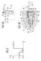
- valve device 26 which at the point Z in the high pressure pump 8 installed, on the one hand serves to vent the injection system when starting the internal combustion engine. on the other hand the fuel flow is via the valve device 26 set for lubrication and cooling of the high pressure pump 8. 2 shows a characteristic curve of the valve device in a diagram 26 shown in operation, the flow cross section Q of the valve device 26 as a function of the pressure p is applied after the feed pump 6. At rest (Section A in FIG.
- valve device 26 gives the valve device 26 a Venting cross-section Q1 free through which in the injection system trapped air, for example in a Driving the fuel tank 2 empty or due to leaks got into the injection system, escapes and from the Injection system is discharged. After bleeding lies by streaming the essentially air free Fuel flow through the valve device 26 is a higher Flow resistance in the valve device 26. by virtue of the higher flow resistance, the fuel flow is blocked in the valve device 26 and thus builds up a dynamic pressure depending on the degree of venting of the fuel flow is. About the build-up of dynamic pressure Valve device 26 closed, so that the essentially closed flow cross-section Q2 exists (section B in Fig. 2), through which only a leakage current escapes.
- the entire pumped by the pre-feed pump 6 stands Fuel flow for feeding the high pressure pump 8 is available and is the high pressure pump 8 through the fuel line 4 fed. If there is more of the pre-feed pump 6 Fuel is delivered as removed from the high pressure pump 8 is, for example, after the engine starts at a higher engine speed, the valve device gives 26 a flow cross section Q3 in the feed 24 for flushing the high pressure pump 8 free (section C in Fig. 2). Accordingly, as can be seen in FIG. 2, none or a low pressure p of the fuel flow after the pre-feed pump 6 in the valve device 26 of the ventilation cross section Released Q1, which is large enough to be one to ensure safe ventilation of the injection system (section A in Fig. 2).
- the valve device reacts here 26 automatically on the applied back pressure the respective operating states of the internal combustion engine and ensures by initially venting the injection system with subsequent regulation of the fuel flow for cooling and flushing the high pressure pump 8 for a rapid pressure build-up in the high pressure accumulator 10.
- FIG. 3a shows a circuit diagram of a first embodiment of a Valve device 26, which is shown in Fig. 1 Position Z is arranged in the injection system according to the invention is.
- the valve device 26 designed as a combination valve 60, which functions one flow control valve and two Throttle devices 30, 32 realized in a compact design.
- the valve device 26 In an inlet line 34 connected to the feed 24 is the second throttle device 32 and in an actuator the valve device 26 is the first throttle device 30 intended.
- the actuator is from a reset device 38 with a holding pressure.
- the actuator is here arranged so that it is in its initial position first connection from the feed line 34 through the second Throttle device 32 and the first throttle device 30 in an inlet channel 40 to the high pressure pump 8 releases.
- the actuator closes the feed 24 to the high pressure pump 8. Furthermore, the actuator is in its third position arranged so that there is a connection from the inlet line 34 through the first throttle device 30 and the inlet channel 40 to the high pressure pump 8 are free.
- the first throttle device 30 serves as a vent throttle, via the one included in the injection system Air escapes, and the second throttle device 32 as Flushing throttle, via which the fuel flow for cooling and Lubrication of the high pressure pump 8 is adjustable.
- valve device 26 3a An embodiment of such a valve device 26 3a is shown schematically in cross section in FIG. 3b.
- the valve device 26 comprises a valve body 42, for example via a thread, not shown is screwed into a housing 44 of the valve device 26.
- the valve body 42 and the housing 44 each have one cylindrical recess 46 with different diameters on, in which the actuator 36 in the form of a cylindrical Piston introduced and guided.
- the actuator 36 is via the resetting device 38 designed as a spring an end surface 48 of the valve body 42 connected.
- drain openings 50 In the End surface 48 are arranged drain openings 50 which are connected to the Fuel return line 20 connected to the fuel tank 2 are. Alternatively, the drain openings can also be connected to the line 40 can be connected.
- the actuator 36 is on the Reset device 38 against the end of the recess 46 of the Housing 44 biased. Furthermore, the valve body 42 has a Inner bore 52, which extends along the longitudinal extent the recess 46 extends and to the inlet channel 40 for High pressure pump 8 is connected. In the actuator 36 are multiple through channels 54 are provided that connect from the feed line 34 to the high pressure pump 8 through the Manufacture actuator 36. In the present case it is the first Throttle device 30, which serves as a vent throttle, in the actuator 36 is integrated and connected to a through-channel 54 connected. The one that acts as a flushing throttle second throttle device 32, on the other hand, is connected to the inlet line 34 connected and in the housing 44 of the valve device 26 installed in front of a valve inlet 56.
- the fuel flow for cooling and lubrication is controlled by the second throttle device 32 set.
- the second throttle device 32 has a larger flow cross section than the first throttle device 30 to one to ensure uniform flushing flow to the high pressure pump 8.
- a leakage flow of the valve device 26 flows into one Spring chamber 58 and is via the drain openings 50 in the Fuel return line 20 discharged.
- the actuator 36 In the starting position, the actuator 36 is due to the Spring force of the return device 38 against the stop of the Housing 44 pressed.
- the actuator 36 is in the recess 46 of the valve device 26 arranged such that a first connection from the feed line 34 through the second throttle device 32, one horizontally in FIG. 3b aligned passage 54, the first throttle device 30, the inner bore 52 of the valve body to the inlet channel 40 of the high pressure pump 8 is released.
- the valve device 26 In the starting position the valve device 26 can pass the air this first connection through the second and the first throttle device be removed from the injection system.
- the first throttle device is built 30 of the actuator 36 due to the small flow cross section a back pressure upon fuel once through the valve device 26 flows.
- the holding pressure of the reset device 38 on the actuator 36 is set so that a low pressure after the pre-feed pump 6 is sufficient, around the actuator 36 from its initial position into a to move the second position to the right.
- In the second Position is a connection between the feed line 34 and the inlet channel 40 interrupted by the actuator 36.
- the inner bore 52 is arranged so that its opening closed by the actuator 36 in the second position is. The first connection via the vent throttle 30 is thus closed and the full fuel flow can of the pre-feed pump 6 of the high pressure pump 8th are fed. This means that pressure builds up quickly the high pressure pump 8 ensured.
- valve device 26 in the present case Case a combination valve 60, which is both the function of a Flow cross section control valve as well as the function of provided as a vent throttle first throttle device 30 includes, and the second designed as a flushing throttle Throttle device 32.
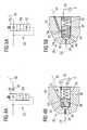
- the structure essentially corresponds 4a of the valve device 26 shown in FIG. 3a, but according to FIG. 4a, the second throttle device 32 connected to the inlet channel 40 to the high pressure pump 8 is.
- FIG. 4b shows an exemplary embodiment for a valve device 26 with the circuit diagram of Fig. 4a.
- the valve body 42 has the cylindrical recess 46 in which the actuator 36 of the valve device 26 is arranged movably.
- the actuator 36 is here via the reset device 38 attached to a closure element 62 for the recess 46 and is reset by the resetting device 38 end of the recess opposite the closure element 62 46 biased in the starting position.
- the Air via the inlet line 34 through the in the actuator 36th integrated first throttle device 30, one on the actuator 36 formed circumferential groove 64 into the inlet channel 40 an interior of the high pressure pump 8 out. If the air completely through this first connection from the inlet pipe 34 via the first throttle device 30 to the high pressure pump 8 has escaped, builds on the vent throttle 30 of the Back pressure on. The dynamic pressure moves the actuator 36 against the holding force of the resetting device 38 from its rest position in a second position in which the first connection closed via the vent throttle 30 and the feed 24 is. In the second position of the actuator 36, the total fuel flow provided by the prefeed pump 6 be fed directly to the high pressure pump 8.
- the pressure increases on to actuator 36 and pushes actuator 36 against the holding force of the resetting device 38 further right to a third position in which a second connection is opened via the second throttle device 32.
- the second Connection runs from the feed line 34 through a Control room 66 located between the left end of the cylindrical Recess 46 and the front surface of the actuator 36 are formed is in the inlet channel 40 and through the as a flushing throttle trained second throttle device 32 to the high pressure pump 8.
- the purge flow to the high pressure pump 8 via the valve device 26 is adjustable. One that occurs during the rinse Leakage flow in the valve device 26 can over that formed in the disc-shaped closure element 62 Drain opening 50 and the fuel return line 20 in the Fuel tank 2 are recycled.
- FIG. 5a is a third embodiment of a circuit diagram a valve device 26 is shown, in which the valve device 26 the functions of the first 30 and the second Throttle device 32 in a compact design in the combination control valve 60 realized.
- Fig. 5b a schematic cross-sectional view illustrated embodiment for a valve device 26 with the circuit diagram 5a, both throttle devices 30, 32 in the actuator 36 of the valve device 26 integrated. in this connection are the first and second throttling devices 30, 32 arranged parallel to each other and each to a through channel 54 of the actuator 36 connected.
- the actuator 36 in the recess 46th of the valve body 42 which is a first connection for venting the injection system from the feed line 34 into the control room 66, through a horizontal passage channel 54 of the actuator 36, the first throttle device 30 into the inlet channel 40 to the interior of the high pressure pump 8 is released.
- the actuator 36 against the spring force the reset device 38 to the right into its second Position shifted so that an opening of the inlet channel 40th closed in the recess 46 by the actuator 36 is.
- the feed 24 is to the High pressure pump 8 interrupted.
- the dynamic pressure continues to rise, causing the actuator 36 continues to the right in its third position moves.
- In the third position is now a second connection from the inlet line 34 into the control room 66, through a portion of the horizontal passageway 54 and the second throttle device acting as a flushing throttle 32 in the inlet channel 40 for flushing the high pressure pump 8 released.
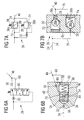
- valve device 26 shows a fourth embodiment of a circuit diagram for a valve device according to the invention.
- the valve device 26 consists of the 3/3-way valve Combination valve 60, the first throttle device 30, which is arranged in the inlet channel 40, and the second Throttle device 32, which in the feed line 34 to the Combination valve 60 is provided.
- FIG. 6b shows an exemplary embodiment of a valve device 26 is shown in cross section with a circuit diagram according to FIG. 6a, in which the actuator 36 one in the cylindrical Recess 46 of the valve body 42 arranged movable Piston is.
- the piston has a circumferential groove 64 which forms an annular channel 68 in the wall of the actuator 36.
- a through channel 54 opens into the ring channel 70 of the actuator 36, so that in the starting position shown in Fig. 6b of the actuator 36, the injection system via a first connection from the inlet line 34 into the control room 66, through the passage channel 54 into the ring channel 70 and through the first connected to the inlet channel 40 Throttle device 30 is released. In this rest position of the actuator 36, the injection system is vented.
- the dynamic pressure at the first throttle device increases 30 and the actuator 36 so that the actuator 36 against the spring force of the resetting device 38 is shifted to the right until the connection between the ring channel 70 and the inlet channel 40 to the high pressure pump 8 interrupted is.
- the valve device is in the second position 26 closed. With increasing back pressure after the Filling the high-pressure pump 8, the actuator 36 is still further against the spring force to the right in its third position postponed.
- the second connection is in the third position released for flushing the high-pressure pump 8 with fuel, from the inlet line 34 through the second one, in the valve body 42 arranged throttle device 32, through the control room 66 and the passage channel 54 in a transfer 80, and then through the drain opening 50, the leakage line 68 runs into the inlet channel 40 to the high pressure pump 8.
- the overpass 80 is a bulge in the Valve body 42 formed on a side wall of the recess 46. Furthermore, a leakage current occurs in the present case over the in the closure element 62 of the recess 46 arranged drain opening 50 and the leakage return line 68 derived into the inlet channel 40.
- FIG. 7a shows a circuit diagram of a valve device according to FIG a fifth embodiment of the invention.
- This includes the valve device 26 two pressure control valves connected in parallel 72, 74.
- the pressure control valves 72, 74 each have an actuator 36 designed as a pressure closing element a, 36 b, each of which is provided by a resetting device 38 a, 38 b, preferably a spring device.
- the first pressure control valve 72 is in the feed 24 arranged to the high pressure pump 8 and includes the first throttle device 30.
- Inlet line 34 branches off from a connecting line 76 from the first pressure control valve 72, after the first pressure control valve 72 again to the feed 24 and the inlet channel 40 is connected to the high pressure pump 8.
- In the connecting line 76 are the second throttle device in succession 32 and the second pressure control valve 74 are provided.
- the first actuator 36 a of the first pressure control valve 72 in the starting position shown of the actuator 36 a the vent cross section Q1 free, which serves the throttling.
- the second actuator 36 b of the second pressure control valve 74 by the holding pressure of the Reset device 38 acts and closes the connecting line 76. From the supplied via the feed line 34 Air can flow through the vent cross section Q1 of the first pressure control valve 72 in the inlet channel 40 escape to the high pressure pump 8.
- the dynamic pressure increases in the first Pressure control valve 72 integrated first throttle device 30 to, so that the first actuator 36 a against the spring force the first reset device 38 a is pressed and in in its second position a valve outlet 78 in the inlet channel 40 closes.
- the restoring force is the second reset device 38 b set such that in the second position of the first actuator 36 a also Connection line 76 closed by the second actuator 36 b is.
- the feed is thus in the second position 24 interrupted to the high pressure pump 8, so that the entire High pressure pump fuel flow for a quick Pressure build-up can be supplied.
- the purge flow to the high pressure pump 8 can via the second throttle device 32, which is before the second Pressure control valve 74 arranged in the connecting line 78 is regulated and set.
Landscapes
- Engineering & Computer Science (AREA)
- Mechanical Engineering (AREA)
- General Engineering & Computer Science (AREA)
- Chemical & Material Sciences (AREA)
- Combustion & Propulsion (AREA)
- Physics & Mathematics (AREA)
- General Physics & Mathematics (AREA)
- Automation & Control Theory (AREA)
- Fuel-Injection Apparatus (AREA)
Description
Es zeigen:
Claims (8)
- Einspritzsystem für eine Brennkraftmaschine mitdadurch gekennzeichnet, dasseiner Vorförderpumpe (6),einer Hochdruckpumpe (8)undeinem Hochdruckspeicher (10)
die über eine Kraftstoffleitung (4) miteinander verbunden sind, um Kraftstoff aus einem Kraftstofftank (2) über die Vorförderpumpe (6) und die Hochdruckpumpe (8) in den Hochdruckspeicher (10) zu fördern undeiner Zuführung (24)
für die Hochdruckpumpe (8), die an der Kraftstoffleitung (4) zwischen der Vorförderpumpe (6) und der Hochdruckpumpe (8) angeschlossen ist, um der Hochdruckpumpe (8) Kraftstoff zur Schmierung und Kühlung zuzuführen und das Einspritzsystem zu entlüften,
eine an die Zuführung (24) angeschlossen Ventileinrichtung (26) vorgesehen ist, die den Kraftstoffstrom zur Schmierung und Kühlung der Hochdruckpumpe regelt und das Einspritzsystem entlüftet, und dass die Ventileinrichtung (26) zumindest ein beweglich angeordnetes Stellglied (36) sowie eine erste (30) und eine zweite Drosseleinrichtung (32) umfasst, wobei das Stellglied (36) in Abhängigkeit von einem Druck des Kraftstoffstroms zwischen der Vorförderpumpe (6) und der Hochdruckpumpe (8) derart eingestellt ist, dass eine erste Verbindung durch die erste Drosseleinrichtung (30) zu der Hochdruckpumpe (8) freigegeben oder die Zuführung (24) zu der Hochdruckpumpe (8) unterbrochen oder eine zweite Verbindung durch die zweite Drosseleinrichtung (32) zu der Hochdruckpumpe (8) freigegeben ist. - Einspritzsystem nach Anspruch 1, dadurch gekennzeichnet, dass die erste (30) und die zweite (32) Drosseleinrichtung unterschiedliche Durchflussquerschnitte aufweisen.
- Einspritzsystem nach Anspruch 1 oder 2, dadurch gekennzeichnet, dass die erste und/oder die zweite Drosseleinrichtung (30, 32) in dem Stellglied (36) integriert ausgebildet ist.
- Einspritzsystem nach zumindest einem der vorhergehenden Ansprüche, dadurch gekennzeichnet, dass das Stellglied (36) zumindest einen Durchgangskanal (54) aufweist.
- Einspritzsystem nach zumindest einem der vorhergehenden Ansprüche, dadurch gekennzeichnet, dass das Stellglied (36) als Durchflussquerschnitt-Stellglied oder Druckstellglied ausgebildet ist.
- Einspritzsystem nach zumindest einem der vorhergehenden Ansprüche, dadurch gekennzeichnet, dass die Ventileinrichtung (26) zumindest ein Wegeventil und/oder zumindest ein Druckbegrenzungsventil umfasst.
- Einspritzsystem nach Anspruch 6, dadurch gekennzeichnet, dass die Drosseleinrichtungen (30, 32), das Wegeventil und/oder das Druckbegrenzungsventil in der Ventileinrichtung (26) zusammengebaut sind.
- Einspritzsystem nach zumindest einem der vorhergehenden Ansprüche, dadurch gekennzeichnet, dass das Stellglied (36) so eingestellt ist, dass die erste Verbindung durch die zweite Drosseleinrichtung (32) und die erste Drosseleinrichtung (30) freigegeben ist.
Applications Claiming Priority (3)
| Application Number | Priority Date | Filing Date | Title |
|---|---|---|---|
| DE10057786 | 2000-11-22 | ||
| DE10057786A DE10057786A1 (de) | 2000-11-22 | 2000-11-22 | Einspritzsystem für eine Brennkraftmaschine und Verfahren zum Regeln und/oder Entlüften eines solchen Einspritzsystems |
| PCT/DE2001/004369 WO2002042633A1 (de) | 2000-11-22 | 2001-11-21 | Einspritzsystem für eine brennkraftmaschine und verfahren zum regeln und/oder entlüften eines solchen einspritzsystems |
Publications (2)
| Publication Number | Publication Date |
|---|---|
| EP1336044A1 EP1336044A1 (de) | 2003-08-20 |
| EP1336044B1 true EP1336044B1 (de) | 2004-04-21 |
Family
ID=7664148
Family Applications (1)
| Application Number | Title | Priority Date | Filing Date |
|---|---|---|---|
| EP01997635A Expired - Lifetime EP1336044B1 (de) | 2000-11-22 | 2001-11-21 | Einspritzsystem für eine brennkraftmaschine und verfahren zum regeln und/oder entlüften eines solchen einspritzsystems |
Country Status (4)
| Country | Link |
|---|---|
| US (1) | US6748923B2 (de) |
| EP (1) | EP1336044B1 (de) |
| DE (2) | DE10057786A1 (de) |
| WO (1) | WO2002042633A1 (de) |
Families Citing this family (33)
| Publication number | Priority date | Publication date | Assignee | Title |
|---|---|---|---|---|
| DE10205187A1 (de) * | 2002-02-08 | 2003-08-21 | Bosch Gmbh Robert | Kraftstoffeinspritzeinrichtung für eine Brennkraftmaschine |
| SE524416C2 (sv) * | 2002-04-23 | 2004-08-03 | Volvo Lastvagnar Ab | Bränsleinsprutningssystem |
| US7100573B2 (en) * | 2002-04-23 | 2006-09-05 | Volvo Lastvagnar Ab | Fuel injection system |
| DE10242591A1 (de) * | 2002-09-13 | 2004-03-25 | Robert Bosch Gmbh | Kraftstoffeinspritzanlage für Brennkraftmaschinen |
| DE10358864A1 (de) * | 2003-12-16 | 2005-07-14 | Volkswagen Ag | Kraftstoffversorgungseinrichtung für eine Brennkraftmaschine sowie Verfahren zum Betreiben dieser |
| JP2005188432A (ja) * | 2003-12-26 | 2005-07-14 | Bosch Automotive Systems Corp | 燃料供給装置 |
| DE102004016724B4 (de) * | 2004-04-05 | 2009-01-02 | Continental Automotive Gmbh | Verfahren zum Überwachen einer Kraftstoffzuführeinrichtung einer Brennkraftmaschine |
| EP1657430B1 (de) * | 2004-11-12 | 2008-05-07 | C.R.F. Società Consortile per Azioni | Ein Kraftstoffeinspritzsystem mit Akkumulatorvolumen für eine Brennkraftmaschine |
| DE102005022738A1 (de) * | 2005-05-18 | 2006-11-23 | Schaeffler Kg | Druckventil für eine Kraftstoffeinspritzvorrichtung einer Brennkraftmaschine |
| DE102005033638A1 (de) * | 2005-07-19 | 2007-01-25 | Robert Bosch Gmbh | Kraftstoff-Fördereinrichtung, insbesondere für eine Brennkraftmaschine |
| DE102006013165A1 (de) * | 2006-03-22 | 2007-09-27 | Robert Bosch Gmbh | Kraftstoffhochdruckpumpe und Kraftstoffeinspritzsystem für eine Brennkraftmaschine |
| ATE542994T1 (de) * | 2008-08-29 | 2012-02-15 | Delphi Tech Holding Sarl | Verbessertes brennstoffdruckregulationssystem und verbesserter brennstoffdruckregulator zur verwendung darin |
| EP2593660A4 (de) * | 2010-07-14 | 2014-01-29 | Volvo Lastvagnar Ab | Brennstoffeinspritzsystem mit druckgesteuerter ausflussfunktion |
| US8590510B2 (en) | 2010-08-24 | 2013-11-26 | Ford Global Technologies, Llc | Fuel system for a multi-fuel engine |
| US8776764B2 (en) | 2011-01-04 | 2014-07-15 | Ford Global Technologies, Llc | Fuel system for a multi-fuel engine |
| US9316187B2 (en) * | 2011-01-18 | 2016-04-19 | Carter Fuel Systems, Llc | Diesel fuel system with advanced priming |
| US9303605B2 (en) * | 2011-11-10 | 2016-04-05 | GM Global Technology Operations LLC | System and method for circulating fuel through a direct injection pump of a bi-fuel engine |
| US20130291838A1 (en) * | 2012-05-04 | 2013-11-07 | Ronnie Lee Booth | Diesel bleeder |
| DE102012212892B4 (de) | 2012-07-24 | 2021-12-30 | Vitesco Technologies GmbH | Einspritzeinrichtung für eine Verbrennungskraftmaschine |
| DE102013201906A1 (de) * | 2013-02-06 | 2014-08-21 | Robert Bosch Gmbh | Hochdruckpumpe mit integriertem Differenzdruckventil |
| US9567915B2 (en) * | 2013-03-07 | 2017-02-14 | GM Global Technology Operations LLC | System and method for controlling a low pressure pump to prevent vaporization of fuel at an inlet of a high pressure pump |
| DE102013204093B4 (de) * | 2013-03-11 | 2021-03-18 | Mtu Friedrichshafen Gmbh | Verfahren zur Entlüftung einer Kraftstoffversorgungsleitung und Brennkraftmaschine |
| DE102013216889B4 (de) * | 2013-08-26 | 2016-08-11 | Robert Bosch Gmbh | Überströmventil für ein Kraftstoffeinspritzsystem sowie Kraftstoffeinspritzsystem |
| US9587578B2 (en) | 2013-12-06 | 2017-03-07 | Ford Global Technologies, Llc | Adaptive learning of duty cycle for a high pressure fuel pump |
| US9458806B2 (en) | 2014-02-25 | 2016-10-04 | Ford Global Technologies, Llc | Methods for correcting spill valve timing error of a high pressure pump |
| US9243598B2 (en) | 2014-02-25 | 2016-01-26 | Ford Global Technologies, Llc | Methods for determining fuel bulk modulus in a high-pressure pump |
| US9874185B2 (en) | 2014-05-21 | 2018-01-23 | Ford Global Technologies, Llc | Direct injection pump control for low fuel pumping volumes |
| GB2532252A (en) * | 2014-11-13 | 2016-05-18 | Gm Global Tech Operations Llc | A fuel injection system of an internal combustion engine |
| US9638153B2 (en) * | 2015-02-20 | 2017-05-02 | Ford Global Technologies, Llc | Method for cooling a direct injection pump |
| US10378500B2 (en) * | 2016-09-27 | 2019-08-13 | Caterpillar Inc. | Protection device for limiting pump cavitation in common rail system |
| IT201700059032A1 (it) * | 2017-05-30 | 2018-11-30 | Bosch Gmbh Robert | Gruppo di pompaggio per alimentare combustibile, preferibilmente gasolio, ad un motore a combustione interna |
| DE102018003797A1 (de) * | 2018-05-09 | 2019-11-14 | Hydac Fluidcarecenter Gmbh | Kraftstofffördervorrichtung |
| DE102023135136A1 (de) * | 2023-12-14 | 2025-06-18 | Hengst Se | Filtermodul für die Fluidfiltration |
Family Cites Families (8)
| Publication number | Priority date | Publication date | Assignee | Title |
|---|---|---|---|---|
| DE3801929C2 (de) * | 1987-01-30 | 1998-07-02 | Volkswagen Ag | Kraftstoffeinspritzeinrichtung |
| DE19742180C2 (de) * | 1997-09-24 | 1999-07-08 | Siemens Ag | Einspritzsystem für eine Brennkraftmaschine und Verfahren zum Regeln eines Einspritzsystems |
| DE19801355B4 (de) * | 1998-01-16 | 2004-04-08 | Robert Bosch Gmbh | Hochdruckpumpe zur Kraftstoffversorgung bei Kraftstoffeinspritzsystemen von Brennkraftmaschinen |
| DE19818385A1 (de) * | 1998-04-24 | 1999-10-28 | Bosch Gmbh Robert | Zuschaltventil in einem Kraftstoffeinspritzsystem für Brennkraftmaschinen |
| DE19900562C2 (de) * | 1999-01-09 | 2000-11-16 | Bosch Gmbh Robert | Common-Rail-System |
| DE19907311A1 (de) * | 1999-02-22 | 2000-08-31 | Bosch Gmbh Robert | Hydraulikpumpeneinheit |
| DE10048247A1 (de) * | 2000-09-29 | 2002-04-11 | Bosch Gmbh Robert | Kraftstoffversorgungseinrichtung für eine Brennkraftmaschine |
| JP3852753B2 (ja) * | 2001-12-04 | 2006-12-06 | 株式会社デンソー | 燃料噴射ポンプ |
-
2000
- 2000-11-22 DE DE10057786A patent/DE10057786A1/de not_active Withdrawn
-
2001
- 2001-11-21 EP EP01997635A patent/EP1336044B1/de not_active Expired - Lifetime
- 2001-11-21 WO PCT/DE2001/004369 patent/WO2002042633A1/de not_active Ceased
- 2001-11-21 DE DE50102083T patent/DE50102083D1/de not_active Expired - Lifetime
-
2003
- 2003-05-07 US US10/431,107 patent/US6748923B2/en not_active Expired - Lifetime
Also Published As
| Publication number | Publication date |
|---|---|
| US6748923B2 (en) | 2004-06-15 |
| EP1336044A1 (de) | 2003-08-20 |
| WO2002042633A1 (de) | 2002-05-30 |
| DE50102083D1 (de) | 2004-05-27 |
| US20030188716A1 (en) | 2003-10-09 |
| DE10057786A1 (de) | 2002-06-06 |
Similar Documents
| Publication | Publication Date | Title |
|---|---|---|
| EP1336044B1 (de) | Einspritzsystem für eine brennkraftmaschine und verfahren zum regeln und/oder entlüften eines solchen einspritzsystems | |
| DE19618707C2 (de) | Verfahren und Vorrichtung zur Regelung eines Kraftstoffvolumenstromes | |
| DE60034417T2 (de) | Kraftstoffeinspritzventil für Hubkolbenbrennkraftmaschine | |
| EP1654456B1 (de) | Kraftstoff-einspritzvorrichtung für eine brennkraftmaschine | |
| DE10039773A1 (de) | Kraftstoffversorgungsanlage | |
| WO2016075041A2 (de) | Niederdruckregelsystem einer kraftstofffördereinrichtung eines kraftstoffeinspritzsystems sowie ein absteuerventil dazu | |
| WO2010063414A1 (de) | Hydrostatischer antrieb mit spülvorrichtung | |
| EP1348072B1 (de) | Verfahren, computerprogram und steuer- und/oder regelgerät zum betreiben einer brennkraftmaschine sowie brennkraftmaschine | |
| DE112015005483T5 (de) | Hochdruckpumpe und Kraftstoffzuführsystem unter Verwendung derselben | |
| EP2031237B1 (de) | Einspritzdüse zum Einspritzen von Brennstoff | |
| DE2362359A1 (de) | Vorrichtung zum umwaelzen von abgasen fuer eine verbrennungskraftmaschine | |
| DE1947529C3 (de) | Kraftstoff einspritzpumpe für Brennkraftmaschinen | |
| DE69911323T2 (de) | Kraftstoffversorgungseinheit für Brennkraftmaschine | |
| DE10139055A1 (de) | Verfahren, Computerprogramm, Steuer- und/oder Regelgerät sowie Kraftstoffsystem für eine Brennkraftmaschine | |
| WO2003052262A1 (de) | Niederdruckkreislauf für ein speichereinspritzsystem | |
| DE102005060647A1 (de) | Kraftstoffeinspritzgerät für eine Brennkraftmaschine | |
| EP2468560A1 (de) | Kraftstoffsystem | |
| EP0565552B1 (de) | Leckölfreies speicherladeventil | |
| DE10239747A1 (de) | Hydraulischer Ventilsteller zum Betätigen eines GAswechselventils | |
| EP0864458A1 (de) | Vorrichtung zur Kraftstoffversorgung einer Brennkraftmaschine | |
| DE19719607A1 (de) | Vorrichtung zur Kraftstoffversorgung einer Brennkraftmaschine | |
| DE19708597C1 (de) | Sauggedrosselte Förderpumpe | |
| DE3802102C2 (de) | ||
| DE4404517C2 (de) | Hydraulische Schaltung für einen Ölbrenner | |
| DE4230106C2 (de) |
Legal Events
| Date | Code | Title | Description |
|---|---|---|---|
| PUAI | Public reference made under article 153(3) epc to a published international application that has entered the european phase |
Free format text: ORIGINAL CODE: 0009012 |
|
| 17P | Request for examination filed |
Effective date: 20030402 |
|
| AK | Designated contracting states |
Designated state(s): AT BE CH CY DE DK ES FI FR GB GR IE IT LI LU MC NL PT SE TR |
|
| RIN1 | Information on inventor provided before grant (corrected) |
Inventor name: GROSSNER, THOMAS Inventor name: WERNER, MARTIN Inventor name: HUSSLEIN, KLAUS Inventor name: ZANDER, ECKBERT Inventor name: KLESSE, CHRISTOPH |
|
| GRAP | Despatch of communication of intention to grant a patent |
Free format text: ORIGINAL CODE: EPIDOSNIGR1 |
|
| GRAS | Grant fee paid |
Free format text: ORIGINAL CODE: EPIDOSNIGR3 |
|
| GRAA | (expected) grant |
Free format text: ORIGINAL CODE: 0009210 |
|
| AK | Designated contracting states |
Kind code of ref document: B1 Designated state(s): DE FR GB IT |
|
| REG | Reference to a national code |
Ref country code: GB Ref legal event code: FG4D Free format text: NOT ENGLISH |
|
| REG | Reference to a national code |
Ref country code: IE Ref legal event code: FG4D Free format text: GERMAN |
|
| REF | Corresponds to: |
Ref document number: 50102083 Country of ref document: DE Date of ref document: 20040527 Kind code of ref document: P |
|
| GBT | Gb: translation of ep patent filed (gb section 77(6)(a)/1977) |
Effective date: 20040603 |
|
| REG | Reference to a national code |
Ref country code: IE Ref legal event code: FD4D |
|
| ET | Fr: translation filed | ||
| PLBE | No opposition filed within time limit |
Free format text: ORIGINAL CODE: 0009261 |
|
| STAA | Information on the status of an ep patent application or granted ep patent |
Free format text: STATUS: NO OPPOSITION FILED WITHIN TIME LIMIT |
|
| 26N | No opposition filed |
Effective date: 20050124 |
|
| REG | Reference to a national code |
Ref country code: FR Ref legal event code: TP |
|
| REG | Reference to a national code |
Ref country code: GB Ref legal event code: 732E Free format text: REGISTERED BETWEEN 20110825 AND 20110831 |
|
| REG | Reference to a national code |
Ref country code: FR Ref legal event code: PLFP Year of fee payment: 15 |
|
| PGFP | Annual fee paid to national office [announced via postgrant information from national office to epo] |
Ref country code: IT Payment date: 20151125 Year of fee payment: 15 Ref country code: DE Payment date: 20151130 Year of fee payment: 15 Ref country code: GB Payment date: 20151118 Year of fee payment: 15 |
|
| PGFP | Annual fee paid to national office [announced via postgrant information from national office to epo] |
Ref country code: FR Payment date: 20151119 Year of fee payment: 15 |
|
| REG | Reference to a national code |
Ref country code: DE Ref legal event code: R119 Ref document number: 50102083 Country of ref document: DE |
|
| GBPC | Gb: european patent ceased through non-payment of renewal fee |
Effective date: 20161121 |
|
| REG | Reference to a national code |
Ref country code: FR Ref legal event code: ST Effective date: 20170731 |
|
| PG25 | Lapsed in a contracting state [announced via postgrant information from national office to epo] |
Ref country code: IT Free format text: LAPSE BECAUSE OF NON-PAYMENT OF DUE FEES Effective date: 20161121 Ref country code: FR Free format text: LAPSE BECAUSE OF NON-PAYMENT OF DUE FEES Effective date: 20161130 |
|
| PG25 | Lapsed in a contracting state [announced via postgrant information from national office to epo] |
Ref country code: GB Free format text: LAPSE BECAUSE OF NON-PAYMENT OF DUE FEES Effective date: 20161121 Ref country code: DE Free format text: LAPSE BECAUSE OF NON-PAYMENT OF DUE FEES Effective date: 20170601 |