EP1334903B2 - Freigabemechanismus für Triggerschalter - Google Patents
Freigabemechanismus für Triggerschalter Download PDFInfo
- Publication number
- EP1334903B2 EP1334903B2 EP03000971A EP03000971A EP1334903B2 EP 1334903 B2 EP1334903 B2 EP 1334903B2 EP 03000971 A EP03000971 A EP 03000971A EP 03000971 A EP03000971 A EP 03000971A EP 1334903 B2 EP1334903 B2 EP 1334903B2
- Authority
- EP
- European Patent Office
- Prior art keywords
- release mechanism
- mechanism according
- actuating element
- toothed gear
- shifting part
- Prior art date
- Legal status (The legal status is an assumption and is not a legal conclusion. Google has not performed a legal analysis and makes no representation as to the accuracy of the status listed.)
- Expired - Lifetime
Links
Images


Classifications
-
- B—PERFORMING OPERATIONS; TRANSPORTING
- B62—LAND VEHICLES FOR TRAVELLING OTHERWISE THAN ON RAILS
- B62K—CYCLES; CYCLE FRAMES; CYCLE STEERING DEVICES; RIDER-OPERATED TERMINAL CONTROLS SPECIALLY ADAPTED FOR CYCLES; CYCLE AXLE SUSPENSIONS; CYCLE SIDE-CARS, FORECARS, OR THE LIKE
- B62K23/00—Rider-operated controls specially adapted for cycles, i.e. means for initiating control operations, e.g. levers, grips
- B62K23/02—Rider-operated controls specially adapted for cycles, i.e. means for initiating control operations, e.g. levers, grips hand actuated
- B62K23/06—Levers
-
- B—PERFORMING OPERATIONS; TRANSPORTING
- B62—LAND VEHICLES FOR TRAVELLING OTHERWISE THAN ON RAILS
- B62M—RIDER PROPULSION OF WHEELED VEHICLES OR SLEDGES; POWERED PROPULSION OF SLEDGES OR SINGLE-TRACK CYCLES; TRANSMISSIONS SPECIALLY ADAPTED FOR SUCH VEHICLES
- B62M25/00—Actuators for gearing speed-change mechanisms specially adapted for cycles
- B62M25/02—Actuators for gearing speed-change mechanisms specially adapted for cycles with mechanical transmitting systems, e.g. cables, levers
- B62M25/04—Actuators for gearing speed-change mechanisms specially adapted for cycles with mechanical transmitting systems, e.g. cables, levers hand actuated
-
- Y—GENERAL TAGGING OF NEW TECHNOLOGICAL DEVELOPMENTS; GENERAL TAGGING OF CROSS-SECTIONAL TECHNOLOGIES SPANNING OVER SEVERAL SECTIONS OF THE IPC; TECHNICAL SUBJECTS COVERED BY FORMER USPC CROSS-REFERENCE ART COLLECTIONS [XRACs] AND DIGESTS
- Y10—TECHNICAL SUBJECTS COVERED BY FORMER USPC
- Y10T—TECHNICAL SUBJECTS COVERED BY FORMER US CLASSIFICATION
- Y10T74/00—Machine element or mechanism
- Y10T74/20—Control lever and linkage systems
- Y10T74/20396—Hand operated
- Y10T74/20402—Flexible transmitter [e.g., Bowden cable]
-
- Y—GENERAL TAGGING OF NEW TECHNOLOGICAL DEVELOPMENTS; GENERAL TAGGING OF CROSS-SECTIONAL TECHNOLOGIES SPANNING OVER SEVERAL SECTIONS OF THE IPC; TECHNICAL SUBJECTS COVERED BY FORMER USPC CROSS-REFERENCE ART COLLECTIONS [XRACs] AND DIGESTS
- Y10—TECHNICAL SUBJECTS COVERED BY FORMER USPC
- Y10T—TECHNICAL SUBJECTS COVERED BY FORMER US CLASSIFICATION
- Y10T74/00—Machine element or mechanism
- Y10T74/21—Elements
- Y10T74/2133—Pawls and ratchets
- Y10T74/2136—Pivoted pawls
- Y10T74/214—Multiple tooth
-
- Y—GENERAL TAGGING OF NEW TECHNOLOGICAL DEVELOPMENTS; GENERAL TAGGING OF CROSS-SECTIONAL TECHNOLOGIES SPANNING OVER SEVERAL SECTIONS OF THE IPC; TECHNICAL SUBJECTS COVERED BY FORMER USPC CROSS-REFERENCE ART COLLECTIONS [XRACs] AND DIGESTS
- Y10—TECHNICAL SUBJECTS COVERED BY FORMER USPC
- Y10T—TECHNICAL SUBJECTS COVERED BY FORMER US CLASSIFICATION
- Y10T74/00—Machine element or mechanism
- Y10T74/21—Elements
- Y10T74/2133—Pawls and ratchets
- Y10T74/2141—Sliding pawls
Definitions
- the present invention relates to a release mechanism for gradually releasing the shift cable of a bicycle transmission according to the preamble of claim 1.
- the document FR 2 701 917 discloses a release mechanism for releasing a traction device for controlling bicycle transmissions, comprising a cable reel for winding the prestressed shift cable, a release device for releasing the tensioned by the shift cable Sellspule in the unwinding and an actuating element for initiating the triggering operation and a housing part for receiving and guiding the components wherein the triggering device is formed essentially of a connected to the cable reel toothed disc and equipped with opposite latches rotary part and wherein the pawls engage alternately on the circumference of the toothed disc in holding and fangs of the toothed disc during the tripping process.
- the utility model DE 9015515 shows a step switch for controlling bicycle transmissions, the lever is equipped with a pair of pawls.
- the pawls engage in a toothed disc, which is connected to a cable reel for winding the shift cable.
- the lever Upon actuation of the lever in the mounting direction or release direction of the respective gear is engaged and thus the corresponding associated switching path realized by winding or unwinding of the shift cable on the circumference of the cable reel.
- the lever returns after successful operation, no matter in which direction, always in its ready position.
- friction or locking means are provided, which are arranged in the housing of the switch and cooperate with the cable reel or the toothed disc.
- the pawls are arranged on the lever with respect to the housing such that upon engagement of a pawl in the toothed disc, the respective other pawl is fixed by a lifting device outside the respective effective range of the toothed disc and thus disabled.
- the current position of the cable reel is held by a spring-loaded latching device, which, however, remains effective only up to a certain holding force and then possibly can slip through the uncontrolled cable coil biased by the shift cable.
- the holding force of the locking device is overcome. In this case, the cable reel tensioned by the shift cable is further rotated until the next stop position and the corresponding shift path is released. Occasionally it comes with switching operations in the release direction, due to the non-positive locking device to skip the targeted gear position.
- the aim of the invention is to achieve with the release mechanism proposed here, compared to the cited prior art, a functionally reliable release and holding operation.
- the selected gear is to be fixed positively.
- such a release mechanism consists of a cable reel which is rotatably connected to a toothed disc and a retaining element equipped with retaining pawl, which alternately engages the tooth contour in the release process and thus enables a gradual release of the spring-biased cable.
- a switching operation in the release direction takes place in two sections and is initiated by the actuation of the release lever.
- the retaining pawl is disengaged, so that the cable coil can rotate as far as until the sear pawl rests against a corresponding tooth of the toothed disc.
- the spring-biased release lever returns to its original position, then the squeezing pawl releases the toothed disc, the cable reel continues to rotate due to the upcoming cable tension until the retaining pawl rests against a corresponding tooth of the toothed disc.
- the object of the invention is therefore to provide a release mechanism for the gradual release of the shift cable, which ensures a functionally reliable release and holding operation and a positive fixing of the shift cable in the corresponding gear position with simple and few components.
- step-by-step tripping operation essentially by the interaction of a linearly moving sliding part with a toothed disk, which is connected in a rotationally fixed manner to the cable spool.
- This toothed disc is equipped with holding and safety teeth, which are arranged opposite each other on the circumference.
- the sliding part engages around the toothed disc and has at least one rigid holding and a rigid catch, which alternately engages depending on the current position of the sliding part, in the holding or fangs.
- the retaining pawl In the rest position, the retaining pawl is always in engagement and positively fixes the current switching position or counteracts a rotation of the cable reel. If the sliding part is moved out of the rest position via an actuating element, then the displacement of the holding pawl permits a rotation of the toothed disk or the cable reel tensioned by the cable, until now the likewise displaced catch engages in the catching toothing and prevents further rotation. If the actuator is relieved, then the spring-biased sliding part returns to its original position.
- the squeezing pawl again comes out of the area of the fangs and the toothed disk is further rotated until the holding pawl now engaging in the holding toothing again locks the toothed disk and ends the release process.
- the switching path required for a gear change is thus achieved in two stages, on the one hand by the rotation of the toothed disc to the engagement of the sear and on the other hand by the rotation of the toothed disc to the engagement of the retaining pawl.
- the holding teeth and the holding pawls in contrast to the fangs and catch pawls have a pronounced, coordinated sawtooth contour.
- the steep flank ensures a secure positive locking of the toothed disc in the switching breaks.
- the flat flank supports the avoidance process of the holding tooth during a switching operation in the winding direction.
- the linear guide of the sliding part takes place on the housing part, which also accommodates the axis of the toothed disc or the cable reel, by means of elongated holes and guide pins.
- the guided movement of the sliding part or the release process is very smooth.
- the shift cable tension which is always applied to the cable spool and thus also to the sprocket and which acts in the release direction is used according to the invention.
- the contour of the slot located in the vicinity of the retaining pawl is step-shaped or highly convex. About this contour, the sliding part, the retaining pawl and thus the corresponding holding tooth is slightly moved in the direction of pull, which increases, according to the contour, the required operating force for the release operation.
- the sliding part is the release process manually via an actuator from the rest position, this is the retaining pawl engaged, the intermediate position, this is the sling engaged.
- the actuating element may be a button which acts directly on the sliding part and is guided together with the sliding part on the housing part. Sliding part and operating part can even be firmly connected or form a common component.
- the actuating element is designed as a pivot lever.
- the pivot axis is guided in the housing part and extends substantially either in or parallel to the toothed disc plane or is arranged perpendicular to it. To achieve better ergonomics, the pivot axis can also be arranged slightly inclined to the toothed disc plane.
- a transmission contour is provided on the sliding part and the actuating element.
- the length of the lever and the distance of the transmission contour from the axis of rotation give the effective lever ratio and can be adjusted to the required or desired actuation forces.
- the actuator does not move in a switching operation in the mounting direction, it is held regardless of the current position of the sliding part of a spring, which is supported on the housing part, in its normal position.
- Fig. 1 the arrangement of the components involved essentially in the tripping process is shown without cable reel in the basic position.
- the toothed disc 1 carries on the circumference of the retaining teeth 2 and the fangs 3.
- Holding teeth 2 and fangs 3 are opposite and have different tooth contours.
- the holding teeth 2 have a pronounced sawtooth contour with a steep and a flat flank.
- In the middle of the toothed disc is a bore 4 for receiving a central axis, which is guided in the housing part 5.
- the sliding part 6 has two slot guides 7 and is articulated by two guide pins 8 on the housing part 5 slidably.
- the sliding part 6 surrounds the toothed disc 1 and is equipped with two rigid pawls.
- the retaining pawl 9 engages in the basic position shown in a tooth gap of the retaining teeth 2, while the squeezing pawl 10 is out of engagement of the fangs 3.
- the retaining pawl 9 also has a sawtooth contour, which is matched to the contour of the retaining teeth 2.
- the steep flank ensures a positive fixation of the toothed disc 1 in the normal position and the flat flank facilitates the disengagement of the sliding part 6, when it is switched into the toothed disc 1 in the mounting direction.
- the release process is initiated with the actuating element 11 in that the pivoting lever 12 pivots about the pivot axis 13 and a transfer contour on the actuating element 11 acts on a corresponding mating surface on the sliding part 1.
- the counter surface on the sliding part 1 extends perpendicular to the toothed disc plane. If the pivot lever 12 is released again after actuation, then brings a biasing spring, which is supported on the housing part 5, the pivot lever 12 and a return spring, the sliding part 6 back to the normal position.
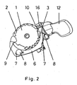
- Fig. 2 shows the release mechanism in the catch position.
- the pivoting pawl 12 is located in the operating position and by means of the transmission contour, which acts on the mating surface 16 on the sliding part 6, the retaining pawl 9 from the region of the retaining teeth 2 moved out.
- the elongated holes 7 in the sliding part 6 and the guide pins 8 lead and limit the linear movement of the sliding part. 6
- Fig. 3 shows the exploded view of the release device with its essential components.
- the actuating element 11 with pivot lever 12 and transmission contour 14 is articulated by means of the pivot axis 13 on the housing part 5.
- the biasing spring 15, which is supported on the housing part 5, holds the actuating element 11 in the basic position.
- the sliding part 6 surrounds the toothed disc 1 and has a rigid retaining pawl 9 and a rigid sear 10 which engage depending on the position of the actuating element 11 in the holding 2 or fangs 3.
- With a transmission contour on the actuating element 11, the release movement of the actuating element 11 is introduced via the mating surface 16 into the sliding part 6.
- the guide pins 8 are fixed in the housing part 5 and ensure a linear movement of the sliding part 6 along the slot guide 7.
- the sliding part 6 is returned by means of the return spring 17 in the basic position, if this allows the actuator 11.
- the cable reel 18 is rotatably connected to the toothed disc 1 and rotates about the centering pin 19 which extends through the bore 4 of the toothed disc 1 and is anchored to the housing part 5.
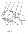
- Fig. 4 shows the release mechanism in plan view.
- the pivot lever 12 is not fully activated yet.
- the transmission contour 14 on the actuating element 11, which acts on the counter surface the sliding part 6 is moved.
- the retaining pawl 9 on the holding tooth 2 is already partially disengaged.
- the pulley 1 and thus also the retaining pawl 9 or the sliding part 6 are pretensioned in the unwinding direction by the rope coil pretensioned by the cable pull.
- the starting contour 20 of the oblong hole of the elongated hole guide 7 is formed so that the sliding part 6 executes a slight evasive movement in the mounting direction on a displacement from the basic position, along the guide pin 8.
Description
- Die vorliegende Erfindung betrifft einen Freigabemechanismus zur stufenweisen Freigabe des Schaltzuges einer Fahrradgangschaltung gemäß dem Oberbegriff von Anspruch 1.
- Das Dokument
FR 2 701 917
wobei die Auslösevorrichtung im wesentlichen aus einer mit der Seilspule verbundenen Zahnscheibe und einem mit gegenüberliegenden Klinken ausgestatteten Drehteil gebildet wird und
wobei die Klinken während des Auslösevorganges wechselweise am Umfang der Zahnscheibe in Halte- und Fangzähne der Zahnscheibe eingreifen. - Das Gebrauchsmuster
DE 9015515 zeigt einen Schrittschalter zur Steuerung von Fahrradgetrieben, dessen Hebel mit einem Klinkenpaar ausgestattet ist. Die Klinken greifen in eine Zahnscheibe, die mit einer Seilspule zum Aufwickeln des Schaltzuges verbunden ist. Bei Betätigung des Hebels in Aufziehrichtung bzw. Freigaberichtung wird der jeweilige Gang eingelegt und damit der entsprechend zugeordnete Schaltweg durch Auf- bzw. Abwickeln des Schaltzuges am Umfang der Seilspule realisiert. Der Schalthebel kehrt nach erfolgter Betätigung, egal in welche Richtung, immer in seine Bereitschaftsstellung zurück. Zum Halten der Seilspule in der jeweils eingeschalteten Position sind Friktions- oder Rasteinrichtungen vorgesehen, die im Gehäuse des Schalters angeordnet sind und mit der Seilspule bzw. der Zahnscheibe zusammenwirken. Die Klinken sind am Hebel in Bezug auf das Gehäuse derart angeordnet, dass beim Einrasten einer Klinke in die Zahnscheibe die jeweils andere Klinke durch eine Aushebevorrichtung außerhalb des jeweiligen Wirkbereiches der Zahnscheibe fixiert und somit außer Funktion gesetzt wird. Die aktuelle Position der Seilspule wird durch eine federbeaufschlagte Rasteinrichtung gehalten, die allerdings nur bis zu einer bestimmten Haltekraft wirksam bleibt und dann möglicherweise die vom Schaltzug vorgespannte Seilspule unkontrolliert durchrutschen läßt. Während des Schaltvorganges, wenn der Schalter in Freigaberichtung betätigt wird, wird die Haltekraft der Rasteinrichtung überwunden. Hierbei wird die vom Schaltzug vorgespannte Seilspule bis zur nächsten Halteposition weiter gedreht und der entsprechende Schaltweg freigegeben. Gelegentlich kommt es bei Schaltvorgängen in Freigaberichtung, aufgrund der kraftschlüssigen Rasteinrichtung zum Überspringen der anvisierten Gangstellung. - Ziel der Erfindung ist es, mit dem hier vorgeschlagenen Freigabemechanismus, gegenüber dem aufgezeigten Stand der Technik, einen funktionssicheren Freigabeund Haltevorgang zu erreichen. Dabei soll die gewählte Gangstufe formschlüssig fixiert werden.
- Im wesentlichen besteht ein solcher Freigabemechanismus aus einer Seilspule, die drehfest mit einer Zahnscheibe verbunden ist und einem mit Halte- und Fangklinken ausgestatteten Halteelement, das beim Freigabevorgang wechselweise in die Zahnkontur eingreift und so eine schrittweise Freigabe des federvorgespannten Seilzuges ermöglicht.
- Ein Schaltvorgang in Freigaberichtung erfolgt in zwei Abschnitten und wird durch die Betätigung des Auslösehebels eingeleitet. Hierdurch wird die Halteklinke außer Eingriff gebracht, so daß sich die Seilspule soweit verdrehen kann, bis die Fangklinke an einem entsprechenden Zahn der Zahnscheibe anliegt. Kehrt der federvorgespannte Auslösehebel in seine Ausgangslage zurück, so gibt die Fangklinke die Zahnscheibe frei, die Seilspule dreht sich aufgrund der anstehenden Seilzugspannung weiter, bis wieder die Halteklinke an einem entsprechenden Zahn der Zahnscheibe anliegt.
- Die Aufgabe der Erfindung ist es nun, einen Freigabemechanismus zur schrittweisen Freigabe des Schaltzuges zu schaffen, der mit einfachen und wenigen Bauteilen einen funktionssicheren Freigabe- und Haltevorgang sowie eine formschlüssige Fixierung des Schaltzuges in der entsprechenden Gangstellung gewährleistet.
- Die Lösung der Aufgabe ist im Anspruch, beschrieben, weitere Ausgestaltungen werden in den Unteransprüchen aufgezeigt.
- Erfindungsgemäß wird vorgeschlagen, den schrittweisen Auslösevorgang im wesentlichen durch das Zusammenwirken eines linear bewegten Schiebeteiles mit einer Zahnscheibe, die mit der Seilspule drehfest verbunden ist, zu bewerkstelligen. Diese Zahnscheibe ist mit Halte- und Fangzähnen ausgestattet, die am Umfang gegenüberliegend angeordnet sind.
- Das Schiebeteil umgreift die Zahnscheibe und verfügt über mindestens einer starren Halte- und einer starren Fangklinke, die wechselweise je nach momentaner Position des Schiebeteils, in die Halte- oder Fangzähne eingreift. In der Ruhestellung befindet sich stets die Halteklinke im Eingriff und fixiert formschlüssig die aktuelle Schaltstellung bzw. wirkt einer Verdrehung der Seilspule entgegen. Wird das Schiebeteil über ein Betätigungselement aus der Ruhestellung heraus bewegt, so erlaubt die Verschiebung der Halteklinke eine Verdrehung der Zahnscheibe bzw. der durch den Schaltzug vorgespannten Seilspule, bis nun die ebenfalls verschobene Fangklinke in die Fangverzahnung eintaucht und ein weiteres Verdrehen verhindert. Wird das Betätigungselement entlastet, dann kehrt das federvorgespannte Schiebeteil wieder in seine Ausgangslage zurück. Dabei gelangt die Fangklinke wieder aus dem Bereich der Fangzähne und die Zahnscheibe wird weiter gedreht bis die nunmehr in die Halteverzahnung eingreifende Halteklinke erneut die Zahnscheibe arretiert und den Freigabevorgang beendet. Der für einen Gangwechsel erforderliche Schaltweg wird somit in zwei Etappen erreicht, zum einen durch das Verdrehen der Zahnscheibe bis zum Eingriff der Fangklinke und zum anderen durch das Verdrehen der Zahnscheibe bis zum Eingriff der Halteklinke.
- Die Haltezähne und die Halteklinken haben im Gegensatz zu den Fangzähnen und Fangklinken eine ausgeprägte, aufeinander abgestimmte Sägezahnkontur. Die steile Flanke sorgt für eine sichere formschlüssige Fixierung der Zahnscheibe in den Schaltpausen. Die flache Flanke unterstützt den Ausweichvorgang des Haltezahnes bei einem Schaltvorgang in Aufziehrichtung.
- Die lineare Führung des Schiebeteils erfolgt am Gehäuseteil, das auch die Achse der Zahnscheibe bzw. der Seilspule aufnimmt, mittels Langlöcher und Führungsbolzen. Die geführte Bewegung des Schiebeteils bzw. der Freigabevorgang verläuft sehr leichtgängig. Zur Erhöhung der Freigabekräfte wird erfindungsgemäß, die stets an der Seilspule und damit auch an der Zahnscheibe anliegende und in Freigaberichtung wirkende Schaltzugspannung genutzt. Hierzu ist die Kontur des in der Nähe der Halteklinke gelegenen Langloches stufenförmig oder stark konvex ausgebildet. Über diese Kontur wird das Schiebeteil, die Halteklinke und damit auch der entsprechende Haltezahn geringfügig in Aufziehrichtung bewegt, wodurch sich, entsprechend dem Konturverlauf, die für den Freigabevorgang erforderliche Betätigungskraft erhöht.
- Das Schiebeteil wird beim Freigabevorgang manuell über ein Betätigungselement aus der Ruhestellung, hierbei ist die Halteklinke im Eingriff, zur Zwischenstellung, hierbei ist die Fangklinke im Eingriff, verschoben. Das Betätigungselement kann eine Taste sein, die direkt auf das Schiebeteil wirkt und zusammen mit dem Schiebeteil am Gehäuseteil geführt wird. Schiebeteil und Betätigungsteil können sogar fest miteinander verbunden sein oder ein gemeinsames Bauteil bilden. Vorzugsweise wird das Betätigungselement als Schwenkhebel ausgebildet. Die Schwenkachse wird im Gehäuseteil geführt und verläuft im wesentlichen entweder in bzw. parallel zur Zahnscheibenebene oder ist senkrecht zu ihr angeordnet. Zum Erzielen einer besseren Ergonomie kann die Schwenkachse auch leicht geneigt zur Zahnscheibenebene angeordnet werden. Zur Umformung der Schwenkbewegung des Betätigungselementes in eine Linearbewegung des Schiebeteils, ist eine Übertragungskontur am Schiebeteil und Betätigungselement vorgesehen. Die Länge des Hebels und der Abstand der Übertragungskontur von der Drehachse ergeben das wirksame Hebelverhältnis und können auf die erforderlichen bzw. erwünschten Betätigungskräfte abgestimmt werden. Damit sich das Betätigungselement bei einem Schaltvorgang in Aufziehrichtung nicht bewegt, wird es unabhängig von der momentanen Position des Schiebeteils von einer Feder, die sich am Gehäuseteil abstützt, in seiner Grundstellung gehalten.
- Anhand von Darstellungen wird ein Ausführungsbeispiel zur weiteren Erläuterung der Erfindungsmerkmale gezeigt:
- Fig. 1
- zeigt den Freigabemechanismus in der Grundstellung
- Fig. 2
- zeigt den Freigabemechanismus in der Fangstellung
- Fig. 3
- zeigt eine Explosionsdarstellung mit den wesentlichen Komponenten
- Fig. 4
- zeigt den Freigabemechanismus in der Draufsicht
- In
Fig. 1 wird die Anordnung der im wesentlichen am Auslösevorgang beteiligten Bauteile ohne Seilspule in der Grundstellung gezeigt. Die Zahnscheibe 1 trägt am Umfang die Haltezähne 2 und die Fangzähne 3. Haltezähne 2 und Fangzähne 3 liegen sich gegenüber und haben unterschiedliche Zahnkonturen. Die Haltezähne 2 haben eine ausgeprägte Sägezahnkontur mit einer steilen und einer flachen Flanke. In der Mitte der Zahnscheibe befindet sich eine Bohrung 4 zur Aufnahme einer zentralen Achse, die im Gehäuseteil 5 geführt wird. Das Schiebeteil 6 verfügt über zwei Langlochführungen 7 und wird mit zwei Führungsbolzen 8 am Gehäuseteil 5 verschiebbar angelenkt. Das Schiebeteil 6 umgreift die Zahnscheibe 1 und ist mit zwei starren Klinken ausgestattet. Die Halteklinke 9 greift in der gezeigten Grundstellung in eine Zahnlücke der Haltezähne 2 ein, während die Fangklinke 10 sich außer Eingriff der Fangzähne 3 befindet. Die Halteklinke 9 hat ebenfalls eine Sägezahnkontur, die mit der Kontur der Haltezähne 2 abgestimmt ist. Die steile Flanke gewährleistet eine formschlüssige Fixierung der Zahnscheibe 1 in der Grundstellung und die flache Flanke erleichtert das Ausrücken des Schiebeteils 6, wenn in die Zahnscheibe 1 in Aufziehrichtung geschaltet wird. - Eingeleitet wird der Freigabevorgang mit dem Betätigungselement 11, indem der Schwenkhebel 12 um die Schwenkachse 13 schwenkt und eine Übertragungskontur am Betätigungselement 11 auf eine entsprechende Gegenfläche am Schiebeteil 1 wirkt. Die Gegenfläche am Schiebeteil 1 verläuft dabei senkrecht zur Zahnscheibenebene. Wird der Schwenkhebel 12 nach erfolgter Betätigung wieder freigegeben, so bringt eine Vorspannfeder, die sich am Gehäuseteil 5 abstützt, den Schwenkhebel 12 und eine Rückholfeder das Schiebeteil 6 in die Grundstellung zurück.
-
Fig. 2 zeigt den Freigabemechanismus in der Fangstellung. Hierbei liegt die Fangklinke 10 am entsprechenden Fangzahn 3 an und verhindert ein Verdrehen der Zahnscheibe 1. Der Schwenkhebel 12 befindet sich in der Betätigungsstellung und mittels der Übertragungskontur, die auf die Gegenfläche 16 am Schiebeteil 6 wirkt, wird die Halteklinke 9 aus dem Bereich der Haltezähne 2 heraus bewegt. Die Langlöcher 7 im Schiebeteil 6 und die Führungsbolzen 8 führen und begrenzen die Linearbewegung des Schiebeteils 6. -
Fig. 3 zeigt die Explosionsdarstellung der Freigabevorrichtung mit ihren wesentlichen Bauteilen. Das Betätigungselement 11 mit Schwenkhebel 12 und Übertragungskontur 14 wird mittels der Schwenkachse 13 am Gehäuseteil 5 angelenkt. Die Vorspannfeder 15, die sich am Gehäuseteil 5 abstützt, hält das Betätigungselement 11 in der Grundstellung. Das Schiebeteil 6 umgreift die Zahnscheibe 1 und verfügt über eine starre Halteklinke 9 und eine starre Fangklinke 10, die je nach Stellung des Betätigungselementes 11 in die Halte- 2 bzw. Fangzähne 3 eingreifen. Mit einer Übertragungskontur am Betätigungselement 11 wird die Freigabebewegung des Betätigungselementes 11 über die Gegenfläche 16 in das Schiebeteil 6 eingeleitet. Die Führungsbolzen 8 werden im Gehäuseteil 5 fixiert und gewährleisten eine Linearbewegung des Schiebeteils 6 entlang der Langlochführung 7. Das Schiebeteil 6 wird mittels der Rückholfeder 17 in die Grundstellung zurückgeführt, wenn dies das Betätigungselement 11 erlaubt. Die Seilspule 18 ist drehfest mit der Zahnscheibe 1 verbunden und dreht um den Zentrierbolzen 19, der durch die Bohrung 4 der Zahnscheibe 1 verläuft und am Gehäuseteil 5 verankert ist. -
Fig. 4 zeigt den Freigabemechanismus in der Draufsicht. Der Schwenkhebel 12 ist noch nicht voll betätigt. Über die Übertragungskontur 14 am Betätigungselement 11, die auf die Gegenfläche wirkt, wird das Schiebeteil 6 verschoben. In der gezeigten Stellung ist die Halteklinke 9 am Haltezahn 2 schon teilweise ausgerückt. Durch die vom Seilzug vorgespannte Seilspule wird die Zahnscheibe 1 und damit auch die Halteklinke 9 bzw. das Schiebeteil 6 in Abwickelrichtung vorgespannt. Die Anlaufkontur 20 des Langloches der Langlochführung 7 ist so ausgebildet, dass das Schiebeteil 6 bei einer Verschiebung aus der Grundstellung heraus, entlang des Führungsbolzens 8 eine geringfügige Ausweichbewegung in Aufziehrichtung ausführt. Diese, durch die stufenförmige Anlaufkontur 20 erzwungene Ausweichbewegung gegen die Vorspannkraft des Seilzuges bzw. der Seilspule, führt somit zu einer höheren Betätigungskraft am Schwenkhebel 12. Es ergibt sich jedoch keine Rückwirkung auf die, in Aufziehrichtung erforderliche Betätigungskraft, da hierbei der Führungsbolzen 8 an der, der Anlaufkontur 20 gegenüberliegenden, annähernd gerade verlaufenden Kontur der Langlochführung 7 anliegt. -
- 1
- Zahnscheibe
- 2
- Haltezahn
- 3
- Fangzahn
- 4
- Bohrung
- 5
- Gehäuseteil
- 6
- Schiebeteil
- 7
- Langlochführung
- 8
- Führungsbolzen
- 9
- Halteklinke
- 10
- Fangklinke
- 11
- Betätigungselement
- 12
- Schwenkhebel
- 13
- Schwenkachse
- 14
- Übertragungskontur
- 15
- Vorspannfeder
- 16
- Gegenfläche
- 17
- Rückholfeder
- 18
- Seilspule
- 19
- Zentrierbolzen
- 20
- Anlaufkontur
Claims (14)
- Freigabemechanismus zur Freigabe eines Zugmittels zur Steuerung von Fahrradgetrieben, umfassend eine Seilspule (18) zum Aufwickeln des vorgespannten Schaltzuges, eine Auslösevorrichtung zum Fixieren bzw. Freigeben der durch den Schaltzug vorgespannten Seilspule (18) in Abwickelrichtung und ein Betätigungselement (11) zum Einleiten des Auslösevorganges sowie ein Gehäuseteil (5) zur Aufnahme und Führung der Bauteile,wobei die Auslösevorrichtung im wesentlichen aus einer mit der Seilspule (18) verbundenen Zahnscheibe (1) und einem mit gegenüberliegenden Klinken (9,10) ausgestatteten Schiebeteil (6) gebildet wird undwobei die Klinken (9,10) während des Auslösevorganges wechselweise am Umfang der Zahnscheibe (1) in Halte- (2) und Fangzähne (3) der Zahnscheibe (1) eingreifen, die jeweils in Umfangsrichtung der Zahnscheibe (1) etwa um 180 Grad versetzt am Umfang angeordnet sind.
- Freigabemechanismus nach Anspruch 1,
dadurch gekennzeichnet,dass das Schiebeteil (6) über mindestens eine starre Halte-(9) und Fangklinke (10) verfügt und federnd am Gehäuseteil (5) angelenkt ist, damit das Schiebeteil (6) aus der Fangstellung wieder in die Haltestellung zurückgeführt wird. - Freigabemechanismus nach Anspruch 1,
dadurch gekennzeichnet,dass das Schiebeteil (6), insbesondere mit mindestens einer Langlochführung (7) am Gehäuseteil (5) geführt wird und eine annähernd lineare Bewegung in der Zahnscheibenebene oder parallel zur Zahnscheibenebene ausführt. - Freigabemechanismus nach Anspruch 1,
dadurch gekennzeichnet,dass Mittel zur Erhöhung ausschliesslich der Auslösekraft unter Nutzung der Seilzugspannung vorgesehen sind. - Freigabemechanismus nach Anspruch 2 und Anspruch 4,
dadurch gekennzeichnet,dass das Langloch einer Langlochführung (7) in der Nähe der Halteklinke (9) mit einer Anlaufkontur (20), vorzugsweise mit einer Schräge oder einer Stufe ausgestattet ist, die bei Verschiebung des Schiebeteils (6) aus der Grundstellung heraus die Halteklinke (9) geringfügig gegen die Seilspannung bewegt, wodurch sich die momentane Auslösekraft erhöht. - Freigabemechanismus nach Anspruch 1,
dadurch gekennzeichnet,dass die Haltezähne (2) mit verschiedenen Zahnflanken ausgestattet sind, vorzugsweise eine Sägezahnkontur aufweisen. - Freigabemechanismus nach Anspruch 1,
dadurch gekennzeichnet,dass die Freigabebewegung am Schiebeteil (6) mittels eines Betätigungselements (11) eingeleitet wird und dass am Betätigungselement (11) eine geeignete Übertragungskontur (14) und am Schiebeteil (6) eine entsprechende Gegenfläche (16) vorgesehen ist, die eine nahezu verschleißfreie Übertragung der Freigabebewegung gewährleisten. - Freigabemechanismus nach Anspruch 7,
dadurch gekennzeichnet,dass die Übertragungskontur (14) und die Gegenfläche (16) im wesentlichen senkrecht zur Zahnscheibenebene angeordnet sind. - Freigabemechanismus nach Anspruch 7,
dadurch gekennzeichnet,dass das Betätigungselement (11) um eine, vom Gehäuseteil (5) gestützte Schwenkachse (13) schwenkt, die vorzugsweise parallel zur Ebene der Zahnscheibe (1) verläuft. - Freigabemechanismus nach Anspruch 7,
dadurch gekennzeichnet,dass das Betätigungselement (11) um eine, vom Gehäuseteil (5) gestützte Schwenkachse (13) schwenkt, die vorzugsweise senkrecht zur Zahnscheibenebene verläuft. - Freigabemechanismus nach den Ansprüchen 9 und 10,
dadurch gekennzeichnet,dass die Schwenkbewegung des Betätigungselementes (11) mittels der Übertragungskontur (14) und einer Gegenfläche (16) in eine Linearbewegung des Schiebeteils (6) umgeformt wird. - Freigabemechanismus nach Anspruch 1,
dadurch gekennzeichnet,dass das Betätigungselement (11) eine lineare Bewegung ausführt, die vorzugsweise annähernd parallel zur Zahnscheibenebene verläuft. - Freigabemechanismus nach den Ansprüchen 7 und 12,
dadurch gekennzeichnet,dass Schiebeteil (6) und Betätigungselement (11) ein gemeinsames Bauteil bilden oder mit einem Scharnier verbunden sind. - Freigabemechanismus nach Anspruch 2,
dadurch gekennzeichnet,dass das Schiebeteil (6) und die Rückholfeder (17) ein gemeinsames Bauteil bilden.
Applications Claiming Priority (2)
| Application Number | Priority Date | Filing Date | Title |
|---|---|---|---|
| DE10205278 | 2002-02-08 | ||
| DE10205278.6A DE10205278B4 (de) | 2002-02-08 | 2002-02-08 | Freigabemechanismus |
Publications (4)
| Publication Number | Publication Date |
|---|---|
| EP1334903A2 EP1334903A2 (de) | 2003-08-13 |
| EP1334903A3 EP1334903A3 (de) | 2007-05-30 |
| EP1334903B1 EP1334903B1 (de) | 2008-11-26 |
| EP1334903B2 true EP1334903B2 (de) | 2012-03-07 |
Family
ID=27588497
Family Applications (1)
| Application Number | Title | Priority Date | Filing Date |
|---|---|---|---|
| EP03000971A Expired - Lifetime EP1334903B2 (de) | 2002-02-08 | 2003-01-17 | Freigabemechanismus für Triggerschalter |
Country Status (5)
| Country | Link |
|---|---|
| US (1) | US7194931B2 (de) |
| EP (1) | EP1334903B2 (de) |
| CN (1) | CN100348455C (de) |
| DE (2) | DE10205278B4 (de) |
| TW (1) | TWI248412B (de) |
Families Citing this family (14)
| Publication number | Priority date | Publication date | Assignee | Title |
|---|---|---|---|---|
| DE10224196A1 (de) * | 2002-05-31 | 2003-12-11 | Sram De Gmbh | Seileinzugmechanik für Triggerschalter |
| US7882763B2 (en) * | 2004-07-23 | 2011-02-08 | Shimano, Inc. | Shift control device for a bicycle transmission |
| US9809278B2 (en) * | 2004-09-28 | 2017-11-07 | Shimano, Inc. | Apparatus for reducing an engaging force of an engaging member |
| DE102004051883B4 (de) * | 2004-10-26 | 2020-09-10 | Sram Deutschland Gmbh | Schaltermechanismus für einen Schrittschalter für Fahrräder |
| US7779718B2 (en) * | 2005-03-03 | 2010-08-24 | Sram, Llc | Bicycle shifter |
| US7721621B2 (en) * | 2005-11-04 | 2010-05-25 | Shimano Inc. | Bicycle shift control mechanism |
| US9227689B2 (en) | 2008-01-08 | 2016-01-05 | Shimano Inc. | Bicycle shift operating device |
| DE102008048134C5 (de) * | 2008-09-20 | 2018-09-27 | Sram Deutschland Gmbh | Schalter zur Betätigung eines Getriebes an einem Fahrrad |
| CN102582780B (zh) * | 2012-02-17 | 2013-04-24 | 中山新宝精密科技有限公司 | 具有多方向释放操作的自行车变速换挡机构 |
| US8746105B2 (en) * | 2012-02-24 | 2014-06-10 | Shimano Inc. | Bicycle operating device |
| DE102013216932A1 (de) * | 2013-08-26 | 2015-02-26 | Sram Deutschland Gmbh | Halte- und Freigabemechanik zum Halten und Freigeben einer Seilaufnahmevorrichtung |
| CN106005230A (zh) * | 2016-06-29 | 2016-10-12 | 麦志成 | 一种自行车无级变速器 |
| CN106926969B (zh) * | 2017-03-16 | 2022-06-21 | 珠海蓝图控制器科技有限公司 | 一种自行车换挡器 |
| CN108928430B (zh) * | 2018-08-28 | 2023-08-11 | 珠海蓝图运动科技股份有限公司 | 一种自行车操作机构 |
Citations (8)
| Publication number | Priority date | Publication date | Assignee | Title |
|---|---|---|---|---|
| GB2169065A (en) † | 1984-12-28 | 1986-07-02 | Sturmey Archer Ltd | Indexing mechanisms and controls embodying the same |
| DE9015515U1 (de) † | 1990-11-13 | 1991-03-28 | Fichtel & Sachs Ag, 8720 Schweinfurt, De | |
| DE4413610A1 (de) † | 1993-04-20 | 1994-11-17 | Campagnolo Srl | Steuereinrichtung einer Fahrrad-Gangschaltung |
| EP0785128A2 (de) † | 1996-01-19 | 1997-07-23 | Shimano Inc. | Gangschaltungseinrichtung für ein Fahrrad |
| US5921138A (en) † | 1996-02-14 | 1999-07-13 | Shimano, Inc. | Bicycle shift device having a linearly sliding shift lever |
| EP1134156A2 (de) † | 2000-03-17 | 2001-09-19 | SRAM Deutschland GmbH | Einwegkraftübertragung |
| EP1134158A2 (de) † | 2000-03-17 | 2001-09-19 | Shimano Inc. | Steuerungseinrichtung für eine Fahrradgangschaltung |
| US6502477B1 (en) † | 1999-04-03 | 2003-01-07 | Sram Deutschland Gmbh | Change-speed lever for a bicycle gear |
Family Cites Families (19)
| Publication number | Priority date | Publication date | Assignee | Title |
|---|---|---|---|---|
| CH248670A (de) | 1946-02-26 | 1947-05-15 | Velosfabrik Cosmos B Schild & | Schaltvorrichtung für Wechselgetriebe, insbesondere von Fahr- und Motorrädern. |
| GB645912A (en) * | 1948-05-26 | 1950-11-08 | Birmingham Small Arms Co Ltd | Improvements in and relating to control-lever mechanism |
| JP2594270B2 (ja) * | 1987-03-20 | 1997-03-26 | 株式会社シマノ | 自転車用変速操作装置 |
| DE68913113T2 (de) * | 1988-09-24 | 1994-05-26 | Shimano Kk | Gangschaltungshebel für ein Fahrrad. |
| JPH0313297U (de) * | 1989-06-26 | 1991-02-12 | ||
| JP3065656B2 (ja) * | 1990-11-14 | 2000-07-17 | 株式会社シマノ | 自転車用変速操作装置 |
| JPH04260889A (ja) * | 1991-02-13 | 1992-09-16 | Maeda Kogyo Kk | 自転車用変速操作装置 |
| JP3245188B2 (ja) * | 1991-04-19 | 2002-01-07 | 株式会社シマノ | 自転車用変速操作装置 |
| US5355745A (en) * | 1992-08-12 | 1994-10-18 | Chuan Fei Industrial Limited Company | Bicycle speed controller |
| JP2601207Y2 (ja) * | 1992-12-28 | 1999-11-15 | 株式会社シマノ | 自転車用の変速操作装置 |
| JPH06239287A (ja) * | 1993-02-12 | 1994-08-30 | Mori San Tsuaa:Kk | 自転車用変速操作装置 |
| FR2701917B1 (fr) * | 1993-02-26 | 1995-07-07 | Sachs Ind Sa | Dispositif a deux organes de commande pour derailleur de cycle. |
| US5361645A (en) * | 1993-08-24 | 1994-11-08 | Industrial Technology Research Institute | Shift lever apparatus for use in bicycle |
| JP3449577B2 (ja) * | 1995-05-26 | 2003-09-22 | 株式会社シマノ | 自転車用ブレーキ及び変速操作装置 |
| US5673594A (en) * | 1996-01-03 | 1997-10-07 | Industrial Technology Research Institute | Speed change lever apparatus for use in bicycles |
| US5829313A (en) * | 1997-01-13 | 1998-11-03 | Shimano Inc. | Bicycle derailleur shifting mechanism having indexing configured for use with variety of chain sprocket sets |
| US6095309A (en) * | 1998-11-12 | 2000-08-01 | At Design Inc. | Cycle handlebar actuator |
| DE10016581A1 (de) * | 2000-04-04 | 2001-10-11 | Sram De Gmbh | Schrittschalter |
| ITTO20010011A1 (it) * | 2001-01-11 | 2002-07-11 | Campagnolo Srl | Gruppo integrato di comando del cambio e del freno per una bicicletta. |
-
2002
- 2002-02-08 DE DE10205278.6A patent/DE10205278B4/de not_active Expired - Lifetime
-
2003
- 2003-01-17 EP EP03000971A patent/EP1334903B2/de not_active Expired - Lifetime
- 2003-01-17 DE DE50310819T patent/DE50310819D1/de not_active Expired - Lifetime
- 2003-01-30 CN CNB031021018A patent/CN100348455C/zh not_active Expired - Lifetime
- 2003-02-06 TW TW092102403A patent/TWI248412B/zh not_active IP Right Cessation
- 2003-02-10 US US10/361,543 patent/US7194931B2/en not_active Expired - Lifetime
Patent Citations (8)
| Publication number | Priority date | Publication date | Assignee | Title |
|---|---|---|---|---|
| GB2169065A (en) † | 1984-12-28 | 1986-07-02 | Sturmey Archer Ltd | Indexing mechanisms and controls embodying the same |
| DE9015515U1 (de) † | 1990-11-13 | 1991-03-28 | Fichtel & Sachs Ag, 8720 Schweinfurt, De | |
| DE4413610A1 (de) † | 1993-04-20 | 1994-11-17 | Campagnolo Srl | Steuereinrichtung einer Fahrrad-Gangschaltung |
| EP0785128A2 (de) † | 1996-01-19 | 1997-07-23 | Shimano Inc. | Gangschaltungseinrichtung für ein Fahrrad |
| US5921138A (en) † | 1996-02-14 | 1999-07-13 | Shimano, Inc. | Bicycle shift device having a linearly sliding shift lever |
| US6502477B1 (en) † | 1999-04-03 | 2003-01-07 | Sram Deutschland Gmbh | Change-speed lever for a bicycle gear |
| EP1134156A2 (de) † | 2000-03-17 | 2001-09-19 | SRAM Deutschland GmbH | Einwegkraftübertragung |
| EP1134158A2 (de) † | 2000-03-17 | 2001-09-19 | Shimano Inc. | Steuerungseinrichtung für eine Fahrradgangschaltung |
Also Published As
| Publication number | Publication date |
|---|---|
| TWI248412B (en) | 2006-02-01 |
| DE10205278A1 (de) | 2003-08-21 |
| DE10205278B4 (de) | 2019-03-14 |
| EP1334903A2 (de) | 2003-08-13 |
| CN1436696A (zh) | 2003-08-20 |
| TW200306266A (en) | 2003-11-16 |
| CN100348455C (zh) | 2007-11-14 |
| EP1334903A3 (de) | 2007-05-30 |
| EP1334903B1 (de) | 2008-11-26 |
| US7194931B2 (en) | 2007-03-27 |
| US20030167876A1 (en) | 2003-09-11 |
| DE50310819D1 (de) | 2009-01-08 |
Similar Documents
| Publication | Publication Date | Title |
|---|---|---|
| EP1334903B2 (de) | Freigabemechanismus für Triggerschalter | |
| EP1366981B1 (de) | Freigabemechanismus für Triggerschalter | |
| DE2403238C3 (de) | Kraftfahrzeugtürverschluli mit zwei gegenüberliegenden Sperrklinken und einer Gabelfalle | |
| WO2000032956A2 (de) | Klemmrollenschaltwerk | |
| EP0697826A1 (de) | Schuhverschluss | |
| DE3132103A1 (de) | Fahrrad-gangschaltung | |
| EP0769433A2 (de) | Gurtaufroller mit Gurtstraffer und Kraftbegrenzung | |
| DE3715846A1 (de) | Sicherheitsgurtaufroller mit rueckstrammvorrichtung | |
| EP1468631B1 (de) | Dämpfungsvorrichtung für bewegbare Möbelteile | |
| DE3227094C2 (de) | Passives Fahrzeuginsassen-Rückhaltegurtsystem | |
| DE10358438A1 (de) | Schaltermechanismus für Fahrradgetriebe | |
| EP0736698A1 (de) | Spannratsche | |
| EP3925868B1 (de) | Halterung für ein tragbares schloss | |
| EP2025853B1 (de) | Mitnehmervorrichtung für eine Torantriebsvorrichtung, eine solche Torantriebsvorrichtung und ein Tor | |
| DE2553501A1 (de) | Filmtransport- und verschlusspanneinrichtung fuer photographische kameras | |
| DE202015104446U1 (de) | Laborrührer | |
| DE3924210C2 (de) | Türverriegelung | |
| DE102005022722A1 (de) | Formschlüssige, beidseitige wirkende Schrittmechanik | |
| DE10055403A1 (de) | Auslösemechanismus für getriggerte Fahrradschaltungen | |
| DE10213450B4 (de) | Freigabeeinrichtung für Triggerschalter | |
| EP3009299B1 (de) | Spannratsche | |
| DE102009006497A1 (de) | Schloss, insbesondere Schubriegelschloss, mit erhöhter Schutzwirkung | |
| DE102004064265B3 (de) | Schaltmechanismus für einen Triggerschalter für Fahrräder | |
| DE4128112A1 (de) | Sperrvorrichtung zwischen motor und getriebe | |
| DE102019124449B4 (de) | Abstandshalter |
Legal Events
| Date | Code | Title | Description |
|---|---|---|---|
| PUAI | Public reference made under article 153(3) epc to a published international application that has entered the european phase |
Free format text: ORIGINAL CODE: 0009012 |
|
| AK | Designated contracting states |
Designated state(s): AT BE BG CH CY CZ DE DK EE ES FI FR GB GR HU IE IT LI LU MC NL PT SE SI SK TR |
|
| AX | Request for extension of the european patent |
Extension state: AL LT LV MK RO |
|
| PUAL | Search report despatched |
Free format text: ORIGINAL CODE: 0009013 |
|
| AK | Designated contracting states |
Kind code of ref document: A3 Designated state(s): AT BE BG CH CY CZ DE DK EE ES FI FR GB GR HU IE IT LI LU MC NL PT SE SI SK TR |
|
| AX | Request for extension of the european patent |
Extension state: AL LT LV MK RO |
|
| 17P | Request for examination filed |
Effective date: 20070827 |
|
| AKX | Designation fees paid |
Designated state(s): DE FR NL |
|
| GRAP | Despatch of communication of intention to grant a patent |
Free format text: ORIGINAL CODE: EPIDOSNIGR1 |
|
| GRAS | Grant fee paid |
Free format text: ORIGINAL CODE: EPIDOSNIGR3 |
|
| GRAA | (expected) grant |
Free format text: ORIGINAL CODE: 0009210 |
|
| AK | Designated contracting states |
Kind code of ref document: B1 Designated state(s): DE FR NL |
|
| REF | Corresponds to: |
Ref document number: 50310819 Country of ref document: DE Date of ref document: 20090108 Kind code of ref document: P |
|
| PLBI | Opposition filed |
Free format text: ORIGINAL CODE: 0009260 |
|
| 26 | Opposition filed |
Opponent name: SHIMANO INC. Effective date: 20090825 |
|
| PLAX | Notice of opposition and request to file observation + time limit sent |
Free format text: ORIGINAL CODE: EPIDOSNOBS2 |
|
| NLR1 | Nl: opposition has been filed with the epo |
Opponent name: SHIMANO INC. |
|
| PLAF | Information modified related to communication of a notice of opposition and request to file observations + time limit |
Free format text: ORIGINAL CODE: EPIDOSCOBS2 |
|
| PLBB | Reply of patent proprietor to notice(s) of opposition received |
Free format text: ORIGINAL CODE: EPIDOSNOBS3 |
|
| PUAH | Patent maintained in amended form |
Free format text: ORIGINAL CODE: 0009272 |
|
| STAA | Information on the status of an ep patent application or granted ep patent |
Free format text: STATUS: PATENT MAINTAINED AS AMENDED |
|
| 27A | Patent maintained in amended form |
Effective date: 20120307 |
|
| AK | Designated contracting states |
Kind code of ref document: B2 Designated state(s): DE FR NL |
|
| REG | Reference to a national code |
Ref country code: NL Ref legal event code: T3 |
|
| REG | Reference to a national code |
Ref country code: DE Ref legal event code: R102 Ref document number: 50310819 Country of ref document: DE Effective date: 20120307 |
|
| REG | Reference to a national code |
Ref country code: FR Ref legal event code: PLFP Year of fee payment: 14 |
|
| REG | Reference to a national code |
Ref country code: FR Ref legal event code: PLFP Year of fee payment: 15 |
|
| REG | Reference to a national code |
Ref country code: FR Ref legal event code: PLFP Year of fee payment: 16 |
|
| PGFP | Annual fee paid to national office [announced via postgrant information from national office to epo] |
Ref country code: DE Payment date: 20220131 Year of fee payment: 20 |
|
| PGFP | Annual fee paid to national office [announced via postgrant information from national office to epo] |
Ref country code: NL Payment date: 20220119 Year of fee payment: 20 Ref country code: FR Payment date: 20220119 Year of fee payment: 20 |
|
| REG | Reference to a national code |
Ref country code: DE Ref legal event code: R071 Ref document number: 50310819 Country of ref document: DE |
|
| REG | Reference to a national code |
Ref country code: NL Ref legal event code: MK Effective date: 20230116 |