EP1334255B2 - Verschlussvorrichtung für das schliessen einer öffnung - Google Patents
Verschlussvorrichtung für das schliessen einer öffnung Download PDFInfo
- Publication number
- EP1334255B2 EP1334255B2 EP01971523A EP01971523A EP1334255B2 EP 1334255 B2 EP1334255 B2 EP 1334255B2 EP 01971523 A EP01971523 A EP 01971523A EP 01971523 A EP01971523 A EP 01971523A EP 1334255 B2 EP1334255 B2 EP 1334255B2
- Authority
- EP
- European Patent Office
- Prior art keywords
- shutter
- transmission means
- side edges
- flap
- plane
- Prior art date
- Legal status (The legal status is an assumption and is not a legal conclusion. Google has not performed a legal analysis and makes no representation as to the accuracy of the status listed.)
- Expired - Lifetime
Links
- 230000005540 biological transmission Effects 0.000 claims abstract description 77
- 238000006073 displacement reaction Methods 0.000 claims abstract description 3
- 239000002184 metal Substances 0.000 claims description 41
- 239000011324 bead Substances 0.000 claims description 32
- 239000004020 conductor Substances 0.000 claims description 7
- 239000000463 material Substances 0.000 claims description 7
- 238000001514 detection method Methods 0.000 claims description 4
- 230000006835 compression Effects 0.000 claims 3
- 238000007906 compression Methods 0.000 claims 3
- 101001017827 Mus musculus Leucine-rich repeat flightless-interacting protein 1 Proteins 0.000 description 58
- 238000000926 separation method Methods 0.000 description 9
- 230000008719 thickening Effects 0.000 description 6
- 239000004677 Nylon Substances 0.000 description 5
- 229920001778 nylon Polymers 0.000 description 5
- 238000003825 pressing Methods 0.000 description 4
- 239000011248 coating agent Substances 0.000 description 3
- 238000000576 coating method Methods 0.000 description 3
- 230000005489 elastic deformation Effects 0.000 description 2
- 238000003466 welding Methods 0.000 description 2
- 238000004804 winding Methods 0.000 description 2
- 238000004026 adhesive bonding Methods 0.000 description 1
- 210000000080 chela (arthropods) Anatomy 0.000 description 1
- 238000010276 construction Methods 0.000 description 1
- 239000012777 electrically insulating material Substances 0.000 description 1
- 238000004519 manufacturing process Methods 0.000 description 1
- 239000004033 plastic Substances 0.000 description 1
- 238000004080 punching Methods 0.000 description 1
- 239000012858 resilient material Substances 0.000 description 1
- 239000004753 textile Substances 0.000 description 1
Images







Classifications
-
- E—FIXED CONSTRUCTIONS
- E06—DOORS, WINDOWS, SHUTTERS, OR ROLLER BLINDS IN GENERAL; LADDERS
- E06B—FIXED OR MOVABLE CLOSURES FOR OPENINGS IN BUILDINGS, VEHICLES, FENCES OR LIKE ENCLOSURES IN GENERAL, e.g. DOORS, WINDOWS, BLINDS, GATES
- E06B9/00—Screening or protective devices for wall or similar openings, with or without operating or securing mechanisms; Closures of similar construction
- E06B9/56—Operating, guiding or securing devices or arrangements for roll-type closures; Spring drums; Tape drums; Counterweighting arrangements therefor
-
- E—FIXED CONSTRUCTIONS
- E06—DOORS, WINDOWS, SHUTTERS, OR ROLLER BLINDS IN GENERAL; LADDERS
- E06B—FIXED OR MOVABLE CLOSURES FOR OPENINGS IN BUILDINGS, VEHICLES, FENCES OR LIKE ENCLOSURES IN GENERAL, e.g. DOORS, WINDOWS, BLINDS, GATES
- E06B9/00—Screening or protective devices for wall or similar openings, with or without operating or securing mechanisms; Closures of similar construction
- E06B9/56—Operating, guiding or securing devices or arrangements for roll-type closures; Spring drums; Tape drums; Counterweighting arrangements therefor
- E06B9/58—Guiding devices
- E06B9/581—Means to prevent or induce disengagement of shutter from side rails
-
- E—FIXED CONSTRUCTIONS
- E06—DOORS, WINDOWS, SHUTTERS, OR ROLLER BLINDS IN GENERAL; LADDERS
- E06B—FIXED OR MOVABLE CLOSURES FOR OPENINGS IN BUILDINGS, VEHICLES, FENCES OR LIKE ENCLOSURES IN GENERAL, e.g. DOORS, WINDOWS, BLINDS, GATES
- E06B9/00—Screening or protective devices for wall or similar openings, with or without operating or securing mechanisms; Closures of similar construction
- E06B9/02—Shutters, movable grilles, or other safety closing devices, e.g. against burglary
- E06B9/08—Roll-type closures
- E06B9/11—Roller shutters
- E06B9/13—Roller shutters with closing members of one piece, e.g. of corrugated sheet metal
-
- E—FIXED CONSTRUCTIONS
- E06—DOORS, WINDOWS, SHUTTERS, OR ROLLER BLINDS IN GENERAL; LADDERS
- E06B—FIXED OR MOVABLE CLOSURES FOR OPENINGS IN BUILDINGS, VEHICLES, FENCES OR LIKE ENCLOSURES IN GENERAL, e.g. DOORS, WINDOWS, BLINDS, GATES
- E06B9/00—Screening or protective devices for wall or similar openings, with or without operating or securing mechanisms; Closures of similar construction
- E06B9/56—Operating, guiding or securing devices or arrangements for roll-type closures; Spring drums; Tape drums; Counterweighting arrangements therefor
- E06B9/58—Guiding devices
- E06B2009/585—Emergency release to prevent damage of shutter or guiding device
-
- E—FIXED CONSTRUCTIONS
- E06—DOORS, WINDOWS, SHUTTERS, OR ROLLER BLINDS IN GENERAL; LADDERS
- E06B—FIXED OR MOVABLE CLOSURES FOR OPENINGS IN BUILDINGS, VEHICLES, FENCES OR LIKE ENCLOSURES IN GENERAL, e.g. DOORS, WINDOWS, BLINDS, GATES
- E06B9/00—Screening or protective devices for wall or similar openings, with or without operating or securing mechanisms; Closures of similar construction
- E06B9/56—Operating, guiding or securing devices or arrangements for roll-type closures; Spring drums; Tape drums; Counterweighting arrangements therefor
- E06B9/58—Guiding devices
- E06B2009/587—Mounting of guiding devices to supporting structure
Definitions
- the invention relates to a flap device intended in particular for closing a bay or other opening, by moving the flap relative to guideways.
- One of the essential aims of the present invention is to provide a device that overcomes the aforementioned drawbacks, while being of a simple design and construction and a perfect reliability.
- the device according to the invention is subject to very little wear compared to the devices of the prior art and causes much less noise. It should also be noted that the friction in the guideways during movement of the flap is relatively low, so that the device according to the invention consumes much less energy.
- transmission means are intercalated between the lateral edges of the flap and the guideways and are fixed to the lateral edges of the flap in such a way that as soon as a certain transverse traction force the longitudinal direction of the guideways is exerted on the lateral edges of the flap relative to the transmission means, these edges are partially separated from the latter.
- the transmission means are attached to the lateral edges of the flap by means of attachment.
- the flap has lateral edges projecting from the plane of the flap, these edges being clamped by said transmission means.
- the transmission means have a series of recesses spaced in the direction of movement of the flap which cooperate with drive means for moving the flap along the direction of the guideways.
- the drive means preferably comprise a toothed wheel whose teeth are spaced from each other in order to cooperate with the recesses of the transmission means.
- reintroduction means are provided in order to restore the connection between the transmission means and the flap when opening or closing the shutter if it has been separated from the transmission means.
- these reintroduction means comprising members for exerting a pressing force on the lateral edges of the flap.
- the figure 1 is a schematic side view in section and broken partial of a shutter device according to a particular embodiment of the invention.
- the figure 2 is a schematic view in elevation and front of a shutter device, according to the invention, with several partial sections.
- the figure 3 is a schematic view, in perspective and on a larger scale of a part of a shutter with transmission means, according to a first particular embodiment of the invention.
- the figure 4 is a perspective view of a portion of a shutter with transmission means, according to a second embodiment of the invention.
- the figure 5 is a perspective view of a portion of the transmission means, according to a third specific embodiment of the invention.
- the figure 6 is a perspective view of a part of the transmission means, according to a fourth advantageous embodiment of the invention.
- the figure 7 is a front view of the transmission means of the figure 6 .
- FIGS. 8 to 11 are schematic sectional views of transmission means enclosing an edge of a flap according to different embodiments of the invention.
- the figure 12 is a schematic front view of a toothed wheel according to a particular embodiment of the invention.
- the figure 13 is a schematic side view of the toothed wheel of the figure 12 .
- the figure 14 is a detailed representation on a larger scale of a tooth of the toothed wheel of the figure 12 .
- the figure 15 is a schematic front view of a gear wheel according to another specific embodiment of the invention.
- the figure 16 is a schematic side view of the toothed wheel of the figure 16 .
- the figure 17 is a detailed representation on a larger scale of a tooth of the toothed wheel of the figure 15 .
- the figure 18 is a schematic side view of an anti-jam pad according to the invention.
- the figure 19 is a section, on a larger scale, of means of reintroduction according to line XIX-XIX of the figure 1 .
- the figure 20 is a section, to larger scale, along line XX-XX of the figure 1 .
- the figure 21 is a section, on a larger scale, along line XXI-XXI of the figure 1 .
- the figure 22 is a schematic perspective view of a portion of the free edge of a flap and a portion of the transmission means enclosing the side edge of the flap.
- the figure 23 is a schematic perspective view of a portion of the free edge of a partially disengaged flap with respect to the transmission means.
- the figure 24 shows very schematically an electrical circuit for stopping the shutter when an obstacle is below the flap.
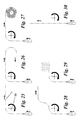
- FIGS. 25 to 30 represent schematic side views of different paths according to which a flap can be moved according to the invention.
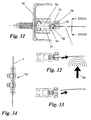
- the figure 31 is a schematic horizontal section of a guideway with transmission means, according to a fifth embodiment of the invention.
- the figure 32 is a detail of the figure 31 when a force is applied to the flap in a direction transverse to the plane of the latter.
- the figure 33 shows means of transmission following the Figures 31 and 32 when the shutter is separated from them.
- the figure 34 is a section following the line XXXIV-XXXIV of the figure 31 .
- the figure 35 is a partial schematic perspective view of the attachment means according to a sixth embodiment of the invention.
- the figure 36 represents the release of the flap of the attachment means of the figure 35 .
- the figure 37 is a schematic perspective view of the attachment means according to a seventh embodiment of the invention.
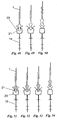
- the Figures 38 to 42 show successive stages of the deformation of a specific bead during the separation of the flap of the transmission means.
- the Figures 43 to 47 show successive stages of the deformation of another specific bead during the separation of the flap of the transmission means.
- the Figures 48 to 50 show successive stages of the deformation of a clamp during the separation of the flap of the transmission means.
- the Figures 51 to 54 show successive stages of the deformation of a clamp and a bead during the separation of the flap of the transmission means.
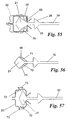
- the figure 55 represents a specific bead with a clamp.
- the figure 56 has another bead provided with an elastic coating.
- the figure 57 shows a bead with a clamp which is provided with a spring.
- the figure 58 is a front view of a very interesting embodiment of the transmission means with a flap, according to the invention.
- the figure 59 is a transversal view of the transmission means and the shutter of the figure 58 with particular guideways, according to the invention.
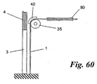
- the figure 60 is a schematic side sectional view of a shutter device provided with a rigid plate according to a specific embodiment of the invention.
- the figure 61 is a cross section of a guide path, according to the invention, provided with a locking system.
- the figure 62 is a cross section of a guide path, according to the invention, provided with another locking system.
- the figure 63 is a schematic front view of a toothed wheel with transmission means according to the invention.
- the figure 64 is a section of the toothed wheel and transmission means along line LXIV-LXIV of the figure 63 .
- the figure 65 is a section, on a larger scale, following line LXV -LXV of the figure 64 .
- the figure 66 is a schematic view in detail of a part of the transmission means and the toothed wheel according to the invention.
- the device comprises a shutter 1 that can move, between a closed position and an open position, in the direction of the arrow 2 and intended for the closure of a bay 3 or any opening or passage in a wall 4.
- the device is shown in its closed position with the free edge 16 of the shutter 1 against the ground 17.
- any element that is at least partially flexible, flexible, rigid or semi-rigid such as a tarpaulin, a plastic strip, a assembly of articulated slats, a grid, etc.
- the figures relate to a flap consisting of a tarpaulin 1 whose side edges 9 and 10 are formed by a strip optionally made of another material which is, for example, only flexible in its longitudinal direction. This strip is fixed to the sheet by gluing, welding or any other means.
- the shutter 1 is guided by transmission means 5 and 6 in guideways 7 and 8 which have a vertical part on either side of the bay 3 and a portion extending substantially horizontally to a level situated on the 3.
- guideways 7 and 8 which have a vertical part on either side of the bay 3 and a portion extending substantially horizontally to a level situated on the 3.
- the transmission means 5 and 6 cooperate with drive means in order to be able to move the flap 1 in the direction of the arrow 2.
- These drive means comprise two toothed wheels 35 arranged near the two lateral edges 9 and 10.
- the latter is actuated by an electric motor 13.
- the figure 3 represents a particular embodiment of the transmission means 5 or 6.
- These comprise a continuous flexible metal strip 19 provided with hooking means by which the metal strip 19 is fixed to the side edges 9 and 10 of the flap 1.
- the metal strip 19 extends over the entire length of the flap 1 in the plane of the latter.
- the attachment means have a succession of clamps 20 which are independent of each other.
- said clamps 20 can be fixed to the side edges 9 and 10 of the flap 1, they are projecting relative to the plane of the flap 1.
- these side edges 9 and 10 are provided with a bead 21 on which
- a thickening 22 is provided at the side edges 9 and 10, near the bead 21 and on either side of the plane of the flap 1, which has on both sides faces 23 and 24 perpendicular to the plane of the flap 1. The function of the faces 23 and 24 will be described below.
- the clamps 20 consist of two metal strips 25 and 26 mounted on either side of the strip 19 by means of rivets. These strips 25 and 26 have a curved portion 27, respectively 28, which extends beyond the edge of the strip 19, so that the bead 21 is sandwiched between these strips. In order to be able to disengage the shutter 1 with respect to the metal strip 19 and to be able to fix the shutter 1 again to the latter, the clamps 20 can be deformed elastically.
- guiding means are provided to allow the movement of the transmission means, i.e. the metal strip 19, in the longitudinal direction of the guideways 7 and 8.
- These guide means comprise, in the embodiment of the invention as shown in FIG. figure 3 , guiding projections 29 and 30. Said projections 29 and 30 are constituted by the ends of the strips 25 and 26 bent at right angles to the plane of the metal strip 19.
- the projections 29 and 30 are guided in a substantially continuous slot in the guideways 7 and 8, thereby forming a slide in the longitudinal direction thereof.
- the metal strip 19 has, along its edge opposite to that directed towards the flap 1, a succession of spaced recesses 31.
- the spacing and the dimensions of the recesses 31 are such as to allow the toothed wheel 35 to mesh with the metal strip 19 and move the latter in a direction parallel to the guideways 7 and 8.
- FIG 4 is represented a variant of the transmission means 5 or 6 of the figure 3 .
- These transmission means 5 or 6 are provided with attachment means consisting of a succession of clamps 20 comprising two strips 25 and 26 located symmetrically on either side of the metal strip 19 to which they are fixed by welding or by bonding.
- a portion of each of the lamellae 25 and 26 extends beyond the edge of the metal strip 19 and is folded in the form of a hook so as to make it possible to grip the bead 21.
- the end 34 of the lamellae 25 and 26 is folded outwardly, as in the embodiment shown in FIG. figure 3 , in order to easily reintroduce the bead 21 of the shutter 1 between the clamps 20 when the latter has disengaged with respect to these clamps 20.
- the strips, forming the lateral edges of the shutter 9 and 10, are provided with a thickening 22 extending on either side of the plane of the strips along the bead 21.
- the transmission means 5 and 6 consist of a metal strip 19 which forms a whole with the clamps 20.
- the latter are cut by punching followed by stamping, in such a way that alternatively one of the strips extends from one side of the plane of the metal strip and the opposite side of the latter.
- Guide projections 29 and 30 are formed in a similar manner.
- the figure 8 shows a flap 1 which has only a bead 21 without a thickening is expected.
- the side edges 9 or 10 of the shutter 1, shown in FIG. figure 9 are provided with a bead 21 which is spaced from the thickening 22.
- FIG. 10 and 11 show a flap 1 with a bead 21 and a thickening 22 which are substantially similar to those shown in FIG. figure 3 .
- the strip 32 is fixed on both sides of the plane of the flap 1, while in the figure 11 , the strip 32 is attached to one side of the flap 1.
- the Figures 12 to 14 relate to a gear wheel 35 which is part of the drive means.
- the toothed wheel 35 is provided with a central cylindrical hole 38 for mounting on the aforementioned axis 12 and presents teeth 36 spaced apart from each other all around its periphery.
- the tangent 50 at the base of the teeth 36 located in the plane of symmetry of the toothed wheel 35, extends substantially radially relative to the latter. In this way it is avoided that, by the force exerted by the wheel 35 on the transmission means, and in particular on the metal strip 19, the latter moves radially away from the toothed wheel 35.
- the teeth 36 have a section in the form of a half ellipse.
- FIGS. Figures 15 to 17 Another embodiment of a toothed wheel, according to the invention, is shown in FIGS. Figures 15 to 17 .
- the toothed wheel 35 differs from that of the preceding figures by the shape of the teeth 36.
- the latter have the shape of a half ellipsoid.
- a nylon coaxial hub 39 with it is mounted against one of its side faces. This hub 39 is driven by the axis 12, which cooperates with the aforementioned electric motor 13.
- the figure 18 shows a guide shoe 40, at a fixed position, which must be placed in the rudder of the toothed wheel 35 in such a way as to prevent the transmission means from being disengaged with respect thereto.
- This guide shoe 40 has a shape which corresponds partially to the contour of the toothed wheel 35 and is provided with a recess 41, on the side facing the latter, which extends along substantially a quarter of the contour of the toothed wheel 35, and this in such a way as to allow the teeth 36 to move in this recess 41 when the gear 35 is rotating about its axis.
- the metal strip 19 then moves between this guide pad 40 and the toothed wheel 35 preferably without any contact between the latter and the metal strip 19. Thus, any friction between the guide shoe 40 and the metal strip 19 is avoided.
- a traction force transverse to the longitudinal direction of the guide tracks 7 and 8 is exerted on the side edges 9 and 10 of the shutter 1 with respect to the metal strip 19. If this force is sufficiently large, the side edges 9 and 10 are at least partially separated from this metal strip by disengaging the aforementioned bead 21 from the clamps 20.
- the flap 1 is at least partially separated from the guideways 7 and 8, it is avoided that it is damaged or that a serious accident occurs.
- reintroduction means 42 are provided near the upper side of the bay 3 for each of the paths of guidance 7 and 8.
- these reintroduction means 42 comprise members which make it possible to exert a pressing force on the lateral edges 9 and 10 of the shutter 1 in a direction having a component parallel to the plane of the shutter 1 and oriented towards the lateral edges 9 and 10 of this last.
- Said members are formed by two rollers 43 and 44 which are arranged in such a way as to be able to exert such a pressing force on a projecting part of the lateral edges 9 and 10 formed by the thickening 22 mentioned above.
- the bead 21 of the lateral edges 9 and 10 is applied against the folded free ends of the clamps 20.
- the bead 21 is elastically compressed, and, on the other hand, the clamps 20 are elastically deformed so that the bead can fit between the projecting parts of the clamps 20 under the action of the rollers 43 and 44, so that the side edges 9 and 10 are again connected to the transmission means 5 and 6.
- the rollers 43 and 44 shown in figure 19 are arranged obliquely and symmetrically on either side of the plane of the shutter 1. This prevents the side edges 9 and 10 can be blocked, for example, between the guideways 7 and 8 and the rollers 43 and 44. Preferably a distance of the order of 1 mm is maintained between the flap 1 and the rollers 43 and 44 to prevent any friction between the flap 1 and these rollers 43 and 44 when the latter is guided by the guideways 7 and 8 during movement between its open and closed position.
- the bead 21 is automatically reintroduced into the clamps 20 as a result of the rigidity of the side edges 9 and 10 of the shutter 1.
- the guideways 7 and 8 are designed in such a way as to form a slideway for the transmission means 5 and 6.
- the latter comprises four substantially continuous L-shaped sections 45 which are mounted symmetrically with respect to the metal strip 19 of the transmission means 5 or 6.
- the profiles 45 are arranged in such a way as to form a free cross-shaped space in which the metal strip 19 provided with the guide projections 29 and 30 can be moved.
- a support plate 46 which extends transversely to the plane of the shutter 1, is mounted between the profiles 45.
- a U-section section section 47 is fixed, by means of bolts 51, to the support plates 46.
- the metal band 19 having the recesses 31 cooperating with the drive means is in the cavity formed by the profile 47.
- the profiles 45 are advantageously made of an electrically insulating material, such as nylon.
- the guide path 7 or 8 of the figure 20 is shown at the height of the aforementioned gear wheel 35.
- the metal strip 19 is located between the toothed wheel 35 and the anti-jam pad 40, while the teeth 36 extend through the recesses 31 of the metal strip 19 in the recess 41 of the anti-jam pad 40.
- the section 47 is interrupted.
- an electric circuit is formed, as shown schematically in the figure 24 which is connected to a control device 64 in such a way that when the electrical circuit is interrupted, the movement of the shutter 1 is immediately stopped.
- the shutter 1 stops immediately after the free edge 16 of the latter comes into contact with this obstacle and is automatically brought into its shutter. opening position.
- detection means are provided, as shown in FIGS. Figures 22 and 23 .
- These detection means comprise, on the one hand, an electrical conductor 48 incorporated in the lower edge 16 of the shutter 1 and extending over the entire width of the latter so as to form a contact with the transmission means 5 and 6, and, on the other hand, an electrically conductive material forming part of the transmission means and forming with the electrical conductor 48 the aforementioned electrical circuit.
- This electrical circuit is, consequently, constituted by the metal strips 19, the electrical conductor 48 and two electrical wires 65 and 66 which connect the control device 64 with each of the metal strips 19 by contact with conducting brushes 67 and 68.
- metal 19 are electrically insulated from the guideways 7 and 8 as they are guided by sections 45 which are not electrically conductive.
- the gears 35 are also formed of a non-electrically conductive material, such as nylon.
- the toothed wheels 35 may consist of a metal strip in the form of a cylinder which encloses a cylindrical nylon core in order to avoid wear of the toothed wheel 35 and to guarantee that the metal strip 19, and thus this electric circuit, is electrically insulated from the other elements of the closure device.
- the conductive material is formed of a metal coating 49 covering the lateral edge projecting from the shutter 1 near the lower edge 16 of the latter and forming an electrical contact with the transmission means, in particular with the metal strip 19.
- the electric circuit is interrupted when the side edge 9 or 10 is separated from the transmission means 5 or 6 and a signal is given to the control device 64 which automatically causes the shutter 1 to stop and open by acting on the power supply or the motor control 13 of the drive means of the shutter 1.
- the link of the attachment means, i.e. clamps 20, with the side edges 9 and 10 is preferably lower near the lower edge 16 of the latter at other locations.
- FIGS 25 to 30 schematically show various non-limiting embodiments of the manner in which takes place the movement of the flap 1 from its closed position to its open position.
- the figure 25 relates to the embodiment as shown in FIG. figure 1 , in which the flap 1, in its open position, extends substantially horizontally at a level above the bay 3.
- the figure 26 relates to an embodiment which differs from that of the figure 25 in that the flap 1, to bring it into its open position, undergoes a return of 180 ° downwards from the horizontal position shown in FIG. figure 25 .
- this return of 180 ° can take place upwards.
- the flap is, in its open position, wound in a spiral about a horizontal axis parallel to that of the toothed wheels of the drive means.
- the winding axis may coincide with the axis of the aforementioned gears.
- the drive means comprise a telescopic arm cooperating with the upper end of the side edges of the flap 1, as for example described in the application of WO 95/30064 (pages 11 and 12).
- the flap 1 undergoes, to move from its closed position to its open position, after its cooperation with the gear wheels, an upward deflection followed by a horizontal displacement.
- the flap 1 is, in its open position, folded zig-zag after its cooperation with the gears.
- the shutter 1 is vertically displaced in its plane to move from the closed position to its open position.
- the flap 1 and the strip 19 can fold freely zig-zag in a tray provided above the bay 3 during the opening of the latter.
- transmission means 5 and 6 which are particularly interesting for a flap 1 which has a large surface.
- These transmission means 5 and 6 comprise a chain 52 which consists of a succession of spaced parallel rods 53, which are interconnected by articulated plates 54, on the ends of these rods 53.
- a chain 52 having the shape of a bicycle chain.
- the guideways 7 and 8 comprise a profile 55 which has in cross section two L-shaped arms 56 and 57 extending along the guide tracks 7 and 8, in such a way that a slot is provided. between the ends of the arms 56 and 57 in which the rods 53 penetrate with their axis substantially transversely to the direction of movement of the flap 1.
- a flange is formed by the arms 56 and 57 against which the plates 54 support one side of the rods 53 to prevent the chain from emerging from the profile 55.
- the plates 54 on the side of the flap 1 have a rim which extends in a plane parallel to the flap 1 making it possible to fix the chain 52 by means of bolts 58 to the flap 1.
- These bolts 58 are preferably made of a relatively low shear coefficient material, such as nylon, so that when a force is applied to the flap 1 as a result of an obstacle which comes into contact with the flap 1 in the direction of the arrow 59, the bolts 58 break and the flap 1 is at least partially separated from the chain 52, as shown in FIG. figure 33 .
- the Figures 35 and 36 represent hooking means which comprise a continuous gripper which extends over the entire length of the side edges 9 and 10 of the flap 1.
- the bead 21 has a triangular section so that it can be easily gripped in the clamp continues 20.
- the clamps 20 are preferably flexible in the direction transverse to the plane of the flap 1 so that the transmission means can be guided in guideways 7 and 8 which do not are not rectilinear to allow the passage in curves and the winding.
- the attachment means are formed by two differently woven ribbons 62 and 63 which grip by contact. These ribbons 62 and 63 are marketed under the name "Velcro”. Namely a male ribbon and a female ribbon. One of these ribbons is attached to the side edge of the flap 1, the other being secured to the metal strip 19.
- Reintroduction means may be provided which are adapted to the attachment means used.
- the reintroduction means are for example constituted by two rollers which are arranged on either side of the band 19 so that during the opening or closing the shutter 1, these rollers push the ribbons 62 and 63 against each other to restore the link between the shutter 1 and the metal strip 19.
- FIGS. 38 to 42 show the successive stages of the deformation of a compressible bead 21 with a triangular section, during the separation of the flap 1 of the clamps 20.
- FIGS 43 to 47 show the successive steps of the deformation of a T-shaped side edge 9 and 10 during the separation of the flap 1 of the transmission means.
- the Figures 48 to 50 show successive stages of the deformation of the clamps 20 during the separation of the flap 1 of the transmission means in the case where the latter are substantially elastic and the bead 21 is substantially incompressible.
- the clamps 20 and the bead 21 are made of a resilient material so as to be elastically deformable during the separation of the flap 1 of the transmission means.
- the shutter 1 is preferably attached to an elastic manner to the transmission means.
- the bead 21 is provided at the side edges 9 and 10 of the flap 1 and present on either side of the latter a face 69 and 70 which is inclined relative to the plane of the flap 1 in such a way as to form a wedge.
- the clamps 20 rest against these faces 69 and 70.
- the clamps 20 slide on the faces 69 and 70 of the bead 1 without the flap 1 is separated from the clamps 20 if this force is not large enough to cause the separation of the clamps 20 of the flap 1.
- Such a situation is represented by a pincer 20 in phantom. When this force no longer acts on the flap 1, the clamps 20 are guided by the faces 69 and 70 to the flap 1 and tend it.
- a variant of the bead of the figure 55 is represented at the figure 56 .
- the bead 21 also has two faces 69 and 70 inclined relative to the plane of the flap 1. These faces 69 and 70 are coated with an elastically compressible material 71, so that the flap 1 is still stretched when it is connected to the clamps 20 because of the elastic deformation of this material 20, which is for example formed by rubber.
- a part of the clamps 20 is in the form of a spring 72 which can be elastically deformed in the direction of the arrow 73 so as to be able to tension the shutter 1.
- the attachment means are not necessarily made of clamps. So in the figure 58 the flap 1 has at the side edges 9 and 10 a succession of small separate blocks 74, preferably connected in a flexible manner between them. These blocks 74 are, for example, formed by "meshes" of a traditional zipper.
- Each of the guideways 7 and 8, as shown in FIG. figure 59 comprises two longitudinal sections 77 and 78 having a rectangular cross-section. These profiles are provided with flanges 75 and 76 extending on either side of the side edges 9 and 10 of the shutter 1. These flanges 75 and 76 are directed towards each other, so as to partially surround the small blocks 74.
- a metal strip 19 is provided, which can cooperate with drive means, which has hooking means in the form of a serrated edge 79. As shown in FIG. figure 58 this serrated edge meshes with the succession of small blocks 74 fixed to the side edges 9 and 10 of the shutter 1.
- the metal strip 19 is guided in a corresponding recess formed between the sections 77 and 78 and is driven by a toothed wheel 35, not shown in FIGS. Figures 58 and 59 .
- a reintroduction system which is similar to that described in EP 0 272 733 , may be provided to reintroduce the blocks 74 in the guideways 7 and 8.
- the figure 60 represents a closure device in which a single gear 35 is provided at one of the two guideways 7 or 8. For clarity of the figure, these guideways are not shown.
- the shutter 1 is provided with a rigid plate 80 which extends over the entire width of the shutter 1 and which is fixedly connected to the metal strips 19 of each of the edges. 9 and 10 of the flap 1.
- the figure 61 represents a locking system comprising two bars 81 and 82 which extend parallel to the guideways 7 and 8 and which can be moved in the direction of the arrows 83 between an unlocked position, represented by dashed lines, and a position locked shown in solid lines.
- the bars 81 and 82 In the locked position, the bars 81 and 82 extend along the side edges 9 and 10 of the shutter 1, so that the clamps 20 are wedged between these bars 81 and 82 while preventing the bead 21 of the shutter 1 from separate clamps 20.
- the bars 81 and 82 can be locked manually or automatically when the bay 3 is closed by the shutter 1.
- the transmission means consist of a flexible band 86, such as for example a textile strap, provided with a succession of clamps 20 which can be attached to the side edges of a flap 1, not shown in FIGS. FIGS.
- the strip 86 is driven, via the clamps 20, by a toothed wheel 35 which consists of two parallel pulleys 87 and 88 mounted, at a distance from each other, on a common axis of rotation 12 and provided with teeth 36.
- the clamps 20 have two rigid plates 90 and 91 applied on either side against the flexible band 86 by means of rivets 89.
- the plates 90 which are oriented towards the toothed wheel 35 are spaced apart from one another. a distance which is sufficient to allow the strip 86 to be bent against at least a part of the periphery of this toothed wheel 35.
- the rigid pads 91 which are oriented towards the opposite side of the toothed wheel 35, abut freely against each other when the flexible band 86 is guided in straight guideways.
- a thrust force on the flexible strip 86 in the direction of the arrow 92 by the rotation of the toothed wheel 35 to close a bay by the flap 1 which is fixed to the clamps 20.
- edges 94 and 95 of the plates 91 extend between the pulleys 87 and 88 and are folded transversely relative to the plane of these plates. The lateral sides of the edges thus formed then bear against each other during the closure of the shutter 1.
- the rigid pads 91 facing the opposite side of the gear 35, have a width which is greater than the distance between the pulleys 87 and 88 of the gear wheel 35, while the rigid pads 90 and the flexible band 86 have a width that is smaller than this distance.
- these have at each corner a recess 93 in which the teeth 36 can mesh.
- the clamps 20 may consist of a single rigid plate 91 which is fixed to the side of the flexible band 86 which is remote from the gear wheel 35.
- stiffening bars and / or ballast could be incorporated in the flap.
- the guideways 7 and 8 must not be completely straight and may be curved.
- closure device according to the invention is not limited to doors with vertical guideways, but may also have horizontal guideways. In some cases, it is possible to provide only a horizontal guide path to the upper side of a bay, so that the flap is suspended from this guide path.
- the shutter of the device can close from the bottom instead of from the top when the guideways extend vertically.
- the attachment means can be of very different shapes. It is for example possible to provide forceps at the side edges of the flap rather than the metal strip.
- the clamps can also be replaced by bands consisting of magnets.
- the bead 21 is not necessarily continuous, but may, for example, consist of a succession of blocks.
- the invention extends to any shutter device in which transmission means are provided in a detachable manner between the shutter and the guideways.
- the transmission means do not necessarily include a metal strip; this band can indeed be made of any material, flexible or rigid, having sufficient strength.
Landscapes
- Engineering & Computer Science (AREA)
- Structural Engineering (AREA)
- Architecture (AREA)
- Civil Engineering (AREA)
- Operating, Guiding And Securing Of Roll- Type Closing Members (AREA)
- Power-Operated Mechanisms For Wings (AREA)
- Specific Sealing Or Ventilating Devices For Doors And Windows (AREA)
- Transmission Devices (AREA)
- Details Of Garments (AREA)
- Cultivation Receptacles Or Flower-Pots, Or Pots For Seedlings (AREA)
- Catching Or Destruction (AREA)
- Curtains And Furnishings For Windows Or Doors (AREA)
- Shutters For Cameras (AREA)
Claims (22)
- Vorrichtung mit Laden (1), die insbesondere zum Verschließen eines Wandausschnitts (3) oder einer anderen Öffnung bestimmt ist, und zwar durch Bewegung des Ladens (1) in Bezug auf einen oder mehrere Führungswege (7, 8), dadurch gekennzeichnet, dass Übertragungsmittel (5, 6), die mit den Führungswegen (7, 8) zusammenarbeiten und sich entlang der Längsrichtung der Letztgenannten bewegen können, zwischen den Seitenrändern (9, 10) des Ladens (1) und den Führungswegen (7, 8) derart angeordnet sind, dass, wenn eine bestimmte Zugkraft quer zur Längsrichtung der Führungswege (7, 8) auf die Seitenränder (9, 10) des Ladens (1) ausgeübt wird, diese Ränder (9, 10) teilweise von diesen Übertragungsmitteln (5, 6) getrennt werden.
- Vorrichtung nach Anspruch 1, dadurch gekennzeichnet, dass die Übertragungsmittel (5, 6) Ankopplungsmittel (20) umfassen, durch die sie auf abnehmbare Weise an den Seitenrändern (9, 10) des Ladens (1) befestigt sind.
- Vorrichtung nach Anspruch 2, dadurch gekennzeichnet, dass die Ankopplungsmittel eine Aufeinanderfolge von Klemmen (20) umfassen, die voneinander unabhängig sind.
- Vorrichtung nach Anspruch 2, dadurch gekennzeichnet, dass die Ankopplungsmittel eine im Wesentlichen durchgehende Klemme (20) umfassen, die auf abnehmbare Weise die Seitenränder (9, 10) des Ladens (1) umschließt.
- Vorrichtung nach einem der Ansprüche 2 bis 4, dadurch gekennzeichnet, dass die Ankopplungsmittel Druckorgane umfassen, die sich elastisch an beide Seiten der Seitenränder (9, 10) des Ladens (1) anlegen.
- Vorrichtung nach einem der Ansprüche 2 bis 5, dadurch gekennzeichnet, dass die Verbindung der Ankopplungsmittel (20) mit den Seitenrändern (9, 10) des Ladens in der Nähe des unteren Randes (16) des Letztgenannten schwächer ist als an den anderen Stellen.
- Vorrichtung nach einem der Ansprüche 1 bis 6, dadurch gekennzeichnet, dass der Laden (1) Seitenränder (9, 10) aufweist, die in Bezug auf die Ebene des Ladens (1) vorspringen.
- Vorrichtung nach einem der Ansprüche 1 bis 7, dadurch gekennzeichnet, dass die Übertragungsmittel (5, 6) mit einer Aufeinanderfolge von Ausnehmungen (31) versehen sind, die in der Richtung der Bewegung des Ladens (1) voneinander beabstandet sind und mit Antriebsmitteln (35, 36) zusammenarbeiten, die die Bewegung des Ladens (1) in einer Richtung parallel zu den Führungswegen (7, 8) erlauben.
- Vorrichtung nach Anspruch 8, dadurch gekennzeichnet, dass die Antriebsmittel ein Zahnrad (35) umfassen, dessen Zähne (36) voneinander beabstandet sind, um mit den oben genannten Ausnehmungen (31) zusammenarbeiten zu können.
- Vorrichtung nach Anspruch 9, dadurch gekennzeichnet, dass die Tangente (50) der Basis der Zähne (36), die sich in der Symmetrieebene des Zahnrades (35) befindet, die Drehachse des Letztgenannten schneidet.
- Vorrichtung nach einem der Ansprüche 8 bis 10, dadurch gekennzeichnet, dass eine feststehende Anti-Stau-Kufe (40) vorgesehen ist, die sich mindestens teilweise um die Antriebsmittel (35, 36) erstreckt, um zu verhindern, dass die Übertragungsmittel (5, 6) von den Antriebsmitteln (35, 36) gelöst werden.
- Vorrichtung nach einem der Ansprüche 1 bis 11, dadurch gekennzeichnet, dass Wiedereinführungsmittel (42) vorgesehen sind, um die Verbindung zwischen den Übertragungsmitteln (5, 6) und dem Laden (1) beim Öffnen oder Schließen des Ladens (1) wiederherzustellen, wenn der Letztgenannte von den Übertragungsmitteln (5, 6) getrennt wurde, wobei diese Wiedereinführungsmittel (42) Organe (43, 44) umfassen, die es ermöglichen, eine Druckkraft auf die Seitenränder (9, 10) des Ladens in einer Richtung auszuüben, die eine Komponente aufweist, die parallel zur Ebene des Ladens (1) ist und zum Seitenrand (9, 10) des Letztgenannten hin gerichtet ist.
- Vorrichtung nach Anspruch 12, dadurch gekennzeichnet, dass die Organe mindestens eine Rolle (43, 44) aufweisen, die derart montiert ist, dass sie auf einen entsprechenden vorspringenden Teil des Seitenrands (9, 10) des Ladens (1) eine Druckkraft zu den Übertragungsmitteln (5, 6) hin ausüben kann, wenn der Laden von den Übertragungsmitteln (5, 6) getrennt wurde.
- Vorrichtung nach Anspruch 13, dadurch gekennzeichnet, dass die Wiedereinführungsorgane zwei Rollen (43, 44) umfassen, die vorzugsweise symmetrisch beiderseits in Bezug auf die Ebene des Ladens (1) angeordnet sind.
- Vorrichtung nach einem der Ansprüche 1 bis 14, dadurch gekennzeichnet, dass die Übertragungsmittel (5, 6) Führungsmittel (30) aufweisen, die mit den Führungswegen (7, 8) zusammenarbeiten, um die Bewegung der Übertragungsmittel (5, 6) in der Längsrichtung der Führungswege (7, 8) zu ermöglichen.
- Vorrichtung nach Anspruch 15, dadurch gekennzeichnet, dass die Führungsmittel Vorsprünge (30) umfassen, die in einem im Wesentlichen durchgehenden Schlitz in den Führungswegen (7, 8) geführt werden, der auf diese Weise eine Gleitschiene in Längsrichtung der Letztgenannten bildet.
- Vorrichtung nach Anspruch 16, dadurch gekennzeichnet, dass sich die oben genannten Vorsprünge (30) vorzugsweise im Wesentlichen senkrecht beiderseits in Bezug auf die Übertragungsmittel (5, 6) erstrecken.
- Vorrichtung nach einem der Ansprüche 2 bis 17, dadurch gekennzeichnet, dass Erkennungsmittel (48, 49, 64) vorgesehen sind, die ein Signal geben, wenn die Verbindung der Ankopplungsmittel (20) mit den Seitenrändern (7, 8) des Ladens (1) unterbrochen ist.
- Vorrichtung nach Anspruch 18, dadurch gekennzeichnet, dass die Erkennungsmittel elektrische Leiter (48) umfassen, die Teil eines Stromkreises sind und die Übertragungsmittel (5, 6) mit den entsprechenden Seitenrändern (9, 10) des Ladens (1) in der Nähe des freien Rands (16) des Letztgenannten verbinden, so dass ein elektrisches Signal gegeben wird, wenn die Verbindung der Ankopplungsmittel (20) mit einem der Seitenränder (9, 10) in der Nähe des freien Rands (16) des Ladens (1) unterbrochen ist.
- Vorrichtung nach einem der Ansprüche 1 bis 19, dadurch gekennzeichnet, dass die Übertragungsmittel (5, 6) einen im Wesentlichen durchgehenden Streifen (19) umfassen, der aus einem biegsamen, nicht schmiegsamen Material gefertigt ist, wie zum Beispiel einen Metallstreifen, der sich im Wesentlichen in der Ebene des Ladens (1) und im Wesentlichen über die gesamte Länge der Seitenränder (9, 10) des Letztgenannten erstreckt.
- Vorrichtung nach einem der Ansprüche 1 bis 20, dadurch gekennzeichnet, dass die Seitenränder (9, 10) des Ladens (1) eine Verdickung (21) aufweisen, an die sich die Ankopplungsmittel (20) anschmiegen.
- Vorrichtung nach einem der Ansprüche 2 bis 19, dadurch gekennzeichnet, dass die Übertragungsmittel (5, 6) einen im Wesentlichen durchgehenden schmiegsamen Streifen (86) umfassen, der sich im Wesentlichen in der Ebene des Ladens (1) und im Wesentlichen über die gesamte Länge der Seitenränder (9, 10) des Letztgenannten erstreckt, wobei dieser schmiegsame Streifen (86) mit Ankopplungsmitteln versehen ist, die eine Aufeinanderfolge von starren Elementen (91) aufweisen, die frei aufeinander aufliegen können.
Priority Applications (2)
| Application Number | Priority Date | Filing Date | Title |
|---|---|---|---|
| DE60129726.1T DE60129726T3 (de) | 2000-09-25 | 2001-09-13 | Verschlussvorrichtung für das schliessen einer öffnung |
| EP01971523A EP1334255B2 (de) | 2000-09-25 | 2001-09-13 | Verschlussvorrichtung für das schliessen einer öffnung |
Applications Claiming Priority (4)
| Application Number | Priority Date | Filing Date | Title |
|---|---|---|---|
| EP00120844 | 2000-09-25 | ||
| EP00120844A EP1191184A1 (de) | 2000-09-25 | 2000-09-25 | Verschlusseinrichtung für das Schliessen einer Öffnung |
| PCT/BE2001/000154 WO2002025048A1 (fr) | 2000-09-25 | 2001-09-13 | Dispositif a volet destine a la fermeture d'une baie |
| EP01971523A EP1334255B2 (de) | 2000-09-25 | 2001-09-13 | Verschlussvorrichtung für das schliessen einer öffnung |
Publications (3)
| Publication Number | Publication Date |
|---|---|
| EP1334255A1 EP1334255A1 (de) | 2003-08-13 |
| EP1334255B1 EP1334255B1 (de) | 2007-08-01 |
| EP1334255B2 true EP1334255B2 (de) | 2012-07-18 |
Family
ID=8169935
Family Applications (2)
| Application Number | Title | Priority Date | Filing Date |
|---|---|---|---|
| EP00120844A Withdrawn EP1191184A1 (de) | 2000-09-25 | 2000-09-25 | Verschlusseinrichtung für das Schliessen einer Öffnung |
| EP01971523A Expired - Lifetime EP1334255B2 (de) | 2000-09-25 | 2001-09-13 | Verschlussvorrichtung für das schliessen einer öffnung |
Family Applications Before (1)
| Application Number | Title | Priority Date | Filing Date |
|---|---|---|---|
| EP00120844A Withdrawn EP1191184A1 (de) | 2000-09-25 | 2000-09-25 | Verschlusseinrichtung für das Schliessen einer Öffnung |
Country Status (29)
| Country | Link |
|---|---|
| US (1) | US7028741B2 (de) |
| EP (2) | EP1191184A1 (de) |
| JP (1) | JP5238118B2 (de) |
| KR (1) | KR100765598B1 (de) |
| CN (1) | CN1246565C (de) |
| AR (1) | AR030759A1 (de) |
| AT (1) | ATE368793T1 (de) |
| AU (2) | AU9152201A (de) |
| BG (1) | BG65357B1 (de) |
| BR (1) | BR0114055B1 (de) |
| CA (1) | CA2424586C (de) |
| CZ (1) | CZ305425B6 (de) |
| DE (1) | DE60129726T3 (de) |
| DK (1) | DK1334255T4 (de) |
| ES (1) | ES2291351T5 (de) |
| GC (1) | GC0000371A (de) |
| GE (1) | GEP20053518B (de) |
| HU (1) | HU224755B1 (de) |
| MX (1) | MXPA03002651A (de) |
| MY (1) | MY134294A (de) |
| NO (1) | NO326101B1 (de) |
| NZ (1) | NZ525337A (de) |
| PL (1) | PL206399B1 (de) |
| PT (1) | PT1334255E (de) |
| RU (1) | RU2283414C2 (de) |
| SK (1) | SK3492003A3 (de) |
| UA (1) | UA73012C2 (de) |
| WO (1) | WO2002025048A1 (de) |
| ZA (1) | ZA200303052B (de) |
Families Citing this family (41)
| Publication number | Priority date | Publication date | Assignee | Title |
|---|---|---|---|---|
| DE10244662A1 (de) * | 2002-09-24 | 2004-04-01 | Guido Langenbach | Schnellauftor |
| DE60324276D1 (de) * | 2003-09-01 | 2008-12-04 | Crawford Group Ab | Rolltor |
| FR2868464B1 (fr) * | 2004-04-02 | 2008-09-26 | Maviflex Sa | Tablier de porte avec bavette d'etancheite et porte equipee d'un tel tablier |
| US8371357B2 (en) * | 2006-02-06 | 2013-02-12 | Assa Abloy Entrance Systems Ab | System to guide the slats of an industrial roller door to reduce damages after crash |
| US20070199667A1 (en) * | 2006-02-28 | 2007-08-30 | Quanex Corporation | Screen assembly for a frame opening |
| EP1840321A1 (de) * | 2006-03-29 | 2007-10-03 | Dynaco International S.A. | Vorrichtung zum Führen eines Rollvorhangs |
| US8037921B2 (en) * | 2006-06-05 | 2011-10-18 | Rite-Hite Holding Corporation | Track and guide system for a door |
| US20070277943A1 (en) * | 2006-06-05 | 2007-12-06 | Rite-Hite Holding Corporation | Track and guide system for a door |
| US7748431B2 (en) * | 2006-06-05 | 2010-07-06 | Rite-Hite Holding Corporation | Track and guide system for a door |
| JP5242056B2 (ja) * | 2007-01-10 | 2013-07-24 | 文化シヤッター株式会社 | シートシャッター |
| JP2008169588A (ja) * | 2007-01-10 | 2008-07-24 | Bunka Shutter Co Ltd | 複合シャッター |
| EP1956178A1 (de) * | 2007-02-07 | 2008-08-13 | Dynaco International S.A. | Verfahren zur Herstellung eines Rollladens und Verfahren zur Herstellung einer Einheit aus zwei Zahnriemen |
| EP2003284A1 (de) * | 2007-06-13 | 2008-12-17 | Dynaco International S.A. | Verschlussvorrichtung und Element zur Wiedereinführung einer Verschlussvorrichtung in eine Führungsschiene |
| US7708049B2 (en) * | 2007-07-03 | 2010-05-04 | Overhead Door Corporation | Sheet door system with transition wheels |
| US8757239B2 (en) * | 2008-08-26 | 2014-06-24 | Hunter Douglas Inc. | Roll-up retractable covering for architectural openings |
| US8113265B2 (en) | 2009-03-02 | 2012-02-14 | Rite-Hite Holding Corporation | Washdown door |
| GB2471198A (en) * | 2009-06-16 | 2010-12-22 | Amyco Ind Doors Ltd | Roller shutter with detachable portion |
| ITMI20110509A1 (it) * | 2011-03-30 | 2012-10-01 | Sacil Hlb Officine Cormano Srl | Porta avvolgibile |
| US20160319593A1 (en) * | 2011-05-11 | 2016-11-03 | Rajiva A. Dwarka | Retractable curtain panel with track guide |
| CA2801443A1 (en) * | 2012-01-10 | 2013-07-10 | Stoebich Brandschutz Gmbh | Fire and smoke protection system |
| US9249621B2 (en) * | 2012-01-18 | 2016-02-02 | Rajiva A. Dwarka | Coil brush curtain assembly |
| GB2519713B (en) * | 2012-08-29 | 2018-08-08 | Assa Abloy Entrance Systems Ab | Roll-up door and guide system therefor |
| US9416589B2 (en) * | 2012-12-11 | 2016-08-16 | Indotech Industrial Doors Inc. | Deformable guide for a rollable door, rollable door guiding system having a deformable guide, and door using the same |
| US9222304B2 (en) * | 2013-04-12 | 2015-12-29 | Rite-Hite Holding Corporation | Systems and methods to retain and refeed door curtains |
| US9493984B2 (en) | 2013-04-12 | 2016-11-15 | Rite-Hite Holding Corporation | Systems and methods to retain and refeed door curtains |
| ITGE20130079A1 (it) * | 2013-08-07 | 2015-02-08 | Davide Coniglio | Dispositivo di protezione per ambienti a chiusura automatizzata |
| US9695635B2 (en) | 2014-05-15 | 2017-07-04 | Dometic Corporation | Power track awning assembly |
| US9228359B2 (en) * | 2014-05-15 | 2016-01-05 | Dometic Corporation | Rotatable awning with illumination |
| EP3017985B1 (de) * | 2014-11-06 | 2021-01-27 | Inalfa Roof Systems Group B.V. | Sonnenschutzvorrichtung und dazugehöriger flexibler Sonnenschutz |
| USD805458S1 (en) | 2015-05-15 | 2017-12-19 | Dometic Sweden Ab | Accessory base |
| USD805019S1 (en) | 2015-05-15 | 2017-12-12 | Dometic Sweden Ab | Accessory base |
| EP3344184B1 (de) | 2015-09-01 | 2025-04-30 | Mivi Neuroscience, Inc. | Thrombektomievorrichtungen |
| US9719292B1 (en) | 2016-08-03 | 2017-08-01 | Defender Screens International LLC | Self-tensioning magnetic tracks and track assemblies |
| US11421474B2 (en) * | 2016-08-03 | 2022-08-23 | Defender Screens International, Llc | Self-tensioning magnetic tracks and track assemblies |
| EP3887636B1 (de) | 2018-11-30 | 2025-07-02 | Rytec Corporation | Türanordnung mit zwei antriebszahnrädern und zwei entsprechenden antriebsführungen |
| CN112440697B (zh) | 2019-08-27 | 2023-11-24 | 英纳法天窗系统集团有限公司 | 遮阳系统及其部件的制造方法 |
| US12180786B2 (en) | 2020-02-24 | 2024-12-31 | Defender Screens International LLC | Retractable screen systems |
| US20220018187A1 (en) * | 2020-07-14 | 2022-01-20 | Rytec Corporation | Door assembly side column configuration |
| CN111911062B (zh) * | 2020-09-15 | 2024-12-31 | 新乡市达威智能门窗实用技术研究中心 | 一种纱窗滑道及纱窗 |
| EP4334564A2 (de) * | 2021-05-07 | 2024-03-13 | Rite-Hite Holding Corporation | Verfahren und vorrichtung zum betrieb von angetriebenen türen |
| US12352105B2 (en) * | 2022-08-17 | 2025-07-08 | Michael Heissenberg | Screen retention track |
Citations (14)
| Publication number | Priority date | Publication date | Assignee | Title |
|---|---|---|---|---|
| US1393405A (en) † | 1920-10-14 | 1921-10-11 | Louis C Soteros | Screen |
| US1694314A (en) † | 1927-02-19 | 1928-12-04 | Rolscreen Co | Guide-track for screen construction |
| US1786054A (en) † | 1927-02-19 | 1930-12-23 | Rolscreen Co | Roller-screen structure |
| US5025847A (en) † | 1989-06-27 | 1991-06-25 | Rytec Corporation | Apparatus for accommodating application of a force in excess of a predetermined magnitude and closure employing such apparatus |
| US5056579A (en) † | 1987-12-02 | 1991-10-15 | Nergeco | Reinforcing and guiding bar for a flexible curtain in a vertically raisable door |
| US5141043A (en) † | 1989-05-19 | 1992-08-25 | Nergeco Sa | Lifting curtain door |
| EP0508698A2 (de) † | 1991-04-03 | 1992-10-14 | Albany International Corp. | Industrietor mit freigebbarem Holm |
| DE4324641A1 (de) † | 1992-07-22 | 1994-01-27 | Kelley Co Inc | Rolltorkonstruktion |
| EP0623731A1 (de) † | 1991-11-06 | 1994-11-09 | Nergeco S.A. | Rolltor mit verbesserter Dichtungsanordnung |
| US5477902A (en) † | 1992-10-02 | 1995-12-26 | Nergeco (Societe Anonyme) | Goods-handling door comprising a wind-resistant flexible curtain |
| US5743317A (en) † | 1996-07-24 | 1998-04-28 | Rite-Hite Corporation | Impact detection system for industrial doors |
| US5765622A (en) † | 1996-11-08 | 1998-06-16 | Thruways Doorsystems Inc. | Vertically moveable flexible door with releasable bottom bar |
| US5944086A (en) † | 1995-02-10 | 1999-08-31 | Rite-Hite Holding Corporation | Curtain bottom tensioning assembly |
| EP0992650A2 (de) † | 1998-10-05 | 2000-04-12 | Luciano S.r.l. | Biegsame Tür |
Family Cites Families (10)
| Publication number | Priority date | Publication date | Assignee | Title |
|---|---|---|---|---|
| ZA80440B (en) * | 1980-01-15 | 1981-09-30 | G Palmer | Door structure |
| BE906022A (fr) | 1986-12-23 | 1987-04-16 | Coenraets B J | Dispositif a volet. |
| GB2235005B (en) * | 1989-08-03 | 1993-11-24 | Seizo Hayashiguchi | Screen |
| BE1004897A3 (fr) | 1991-05-24 | 1993-02-16 | Coenraets Benoit | Dispositif de fermeture, de separation ou de couverture. |
| JPH06173557A (ja) * | 1992-12-07 | 1994-06-21 | Yoji Imai | シャッター |
| RU2167254C2 (ru) * | 1994-04-29 | 2001-05-20 | Динако Интернасьональ | Устройство закрытия гибкого занавеса |
| US5620039A (en) * | 1995-02-10 | 1997-04-15 | Rytec Corporation | Apparatus for providing a slidingly-separable connection between a movable barrier and a means for guiding the barrier |
| DE19600951C5 (de) * | 1996-01-12 | 2010-12-16 | Roto Frank Ag | Antriebsvorrichtung für einen Rolladen |
| JP2949434B1 (ja) * | 1998-07-31 | 1999-09-13 | 三和シヤッター工業株式会社 | シートシャッターのシート破損防止構造 |
| JP2000160961A (ja) * | 1998-11-24 | 2000-06-13 | Toyo Shutter Co Ltd | シートシャッター装置 |
-
2000
- 2000-09-25 EP EP00120844A patent/EP1191184A1/de not_active Withdrawn
-
2001
- 2001-09-13 GE GE5178A patent/GEP20053518B/en unknown
- 2001-09-13 ES ES01971523T patent/ES2291351T5/es not_active Expired - Lifetime
- 2001-09-13 SK SK349-2003A patent/SK3492003A3/sk unknown
- 2001-09-13 US US10/381,429 patent/US7028741B2/en not_active Expired - Lifetime
- 2001-09-13 HU HU0302898A patent/HU224755B1/hu active IP Right Grant
- 2001-09-13 MX MXPA03002651A patent/MXPA03002651A/es active IP Right Grant
- 2001-09-13 BR BRPI0114055-8A patent/BR0114055B1/pt not_active IP Right Cessation
- 2001-09-13 AU AU9152201A patent/AU9152201A/xx active Pending
- 2001-09-13 WO PCT/BE2001/000154 patent/WO2002025048A1/fr not_active Ceased
- 2001-09-13 CA CA002424586A patent/CA2424586C/fr not_active Expired - Lifetime
- 2001-09-13 CZ CZ2003-830A patent/CZ305425B6/cs not_active IP Right Cessation
- 2001-09-13 EP EP01971523A patent/EP1334255B2/de not_active Expired - Lifetime
- 2001-09-13 CN CNB018162525A patent/CN1246565C/zh not_active Expired - Fee Related
- 2001-09-13 UA UA2003043771A patent/UA73012C2/uk unknown
- 2001-09-13 AT AT01971523T patent/ATE368793T1/de not_active IP Right Cessation
- 2001-09-13 JP JP2002529629A patent/JP5238118B2/ja not_active Expired - Lifetime
- 2001-09-13 PT PT01971523T patent/PT1334255E/pt unknown
- 2001-09-13 RU RU2003112014/03A patent/RU2283414C2/ru active
- 2001-09-13 NZ NZ525337A patent/NZ525337A/en not_active IP Right Cessation
- 2001-09-13 DK DK01971523.4T patent/DK1334255T4/da active
- 2001-09-13 PL PL360600A patent/PL206399B1/pl unknown
- 2001-09-13 KR KR20037004221A patent/KR100765598B1/ko not_active Expired - Fee Related
- 2001-09-13 DE DE60129726.1T patent/DE60129726T3/de not_active Expired - Lifetime
- 2001-09-13 AU AU2001291522A patent/AU2001291522B2/en not_active Ceased
- 2001-09-18 AR ARP010104409A patent/AR030759A1/es active IP Right Grant
- 2001-09-21 MY MYPI20014438A patent/MY134294A/en unknown
- 2001-09-25 GC GCP20011638 patent/GC0000371A/en active
-
2003
- 2003-03-21 BG BG107660A patent/BG65357B1/bg unknown
- 2003-03-24 NO NO20031327A patent/NO326101B1/no not_active IP Right Cessation
- 2003-04-17 ZA ZA200303052A patent/ZA200303052B/en unknown
Patent Citations (14)
| Publication number | Priority date | Publication date | Assignee | Title |
|---|---|---|---|---|
| US1393405A (en) † | 1920-10-14 | 1921-10-11 | Louis C Soteros | Screen |
| US1694314A (en) † | 1927-02-19 | 1928-12-04 | Rolscreen Co | Guide-track for screen construction |
| US1786054A (en) † | 1927-02-19 | 1930-12-23 | Rolscreen Co | Roller-screen structure |
| US5056579A (en) † | 1987-12-02 | 1991-10-15 | Nergeco | Reinforcing and guiding bar for a flexible curtain in a vertically raisable door |
| US5141043A (en) † | 1989-05-19 | 1992-08-25 | Nergeco Sa | Lifting curtain door |
| US5025847A (en) † | 1989-06-27 | 1991-06-25 | Rytec Corporation | Apparatus for accommodating application of a force in excess of a predetermined magnitude and closure employing such apparatus |
| EP0508698A2 (de) † | 1991-04-03 | 1992-10-14 | Albany International Corp. | Industrietor mit freigebbarem Holm |
| EP0623731A1 (de) † | 1991-11-06 | 1994-11-09 | Nergeco S.A. | Rolltor mit verbesserter Dichtungsanordnung |
| DE4324641A1 (de) † | 1992-07-22 | 1994-01-27 | Kelley Co Inc | Rolltorkonstruktion |
| US5477902A (en) † | 1992-10-02 | 1995-12-26 | Nergeco (Societe Anonyme) | Goods-handling door comprising a wind-resistant flexible curtain |
| US5944086A (en) † | 1995-02-10 | 1999-08-31 | Rite-Hite Holding Corporation | Curtain bottom tensioning assembly |
| US5743317A (en) † | 1996-07-24 | 1998-04-28 | Rite-Hite Corporation | Impact detection system for industrial doors |
| US5765622A (en) † | 1996-11-08 | 1998-06-16 | Thruways Doorsystems Inc. | Vertically moveable flexible door with releasable bottom bar |
| EP0992650A2 (de) † | 1998-10-05 | 2000-04-12 | Luciano S.r.l. | Biegsame Tür |
Also Published As
Similar Documents
| Publication | Publication Date | Title |
|---|---|---|
| EP1334255B1 (de) | Verschlussvorrichtung für das schliessen einer öffnung | |
| EP2122102B1 (de) | Vorrichtung mit flexiblem vorhang | |
| EP1518036B1 (de) | Verschlusseinrichtung zum wickeln auf eine welle | |
| CA2675648C (fr) | Dispositif a rideau enroulable | |
| BE1014506A3 (fr) | Dispositif a volet avec element de reintroduction. | |
| CA2647291A1 (fr) | Dispositif de fermeture avec un rideau presentant des bords lateraux flexibles | |
| EP1492934B1 (de) | Türenanlage | |
| EP0937859B1 (de) | Automatische Arretierung für Rolläden | |
| EP0500499B1 (de) | Store | |
| EP1127722B1 (de) | Verdunkelungseinrichtung für Fenster und/oder für Fahrzeugöffnung mit Anwendung von Stangen, und korrespondierendes Fahrzeug | |
| FR2765615A3 (fr) | Volet roulant a lattes orientables | |
| CA3223492A1 (fr) | Dispositif compact de couverture d'une surface comprenant deux essieux pour le deploiement et le retrait de la couverture | |
| EP1980704B1 (de) | Vorrichtung zur Befestigung eines Rollladenvorhangs | |
| BE1017124A6 (fr) | Dispositif a rideau flexible. | |
| FR2614928A1 (fr) | Volet roulant pour porte, fenetre et autres ouvertures | |
| FR2765911A1 (fr) | Dispositif de blocage pour volet roulant | |
| EP2146044B1 (de) | Panzer einer Verdeckungsvorrichtung, insbesondere eines Rollladens | |
| BE1017125A6 (fr) | Dispositif a rideau enroulable. | |
| FR2723270A1 (fr) | Element de couvercle pour chemin de cables | |
| BE1013563A6 (fr) | Procede et dispositif de pose de bande d'affiche. | |
| CH628393A5 (en) | Roller shutter | |
| EP0530168B1 (de) | Sperrvorrichtung für Rolltoren | |
| FR2810591A1 (fr) | Toit ouvrant en toile pour vehicule automobile | |
| BE899475A (fr) | Porte a rideau a ouverture verticale rapide. | |
| EP0965723A1 (de) | Rolladen für Tür, Fenster oder dergleichen |
Legal Events
| Date | Code | Title | Description |
|---|---|---|---|
| PUAI | Public reference made under article 153(3) epc to a published international application that has entered the european phase |
Free format text: ORIGINAL CODE: 0009012 |
|
| 17P | Request for examination filed |
Effective date: 20030417 |
|
| AK | Designated contracting states |
Designated state(s): AT BE CH CY DE DK ES FI FR GB GR IE IT LI LU MC NL PT SE TR |
|
| AX | Request for extension of the european patent |
Extension state: AL LT LV MK RO SI |
|
| REG | Reference to a national code |
Ref country code: SE Ref legal event code: TRCL |
|
| TCNL | Nl: translation of patent claims filed | ||
| GRAP | Despatch of communication of intention to grant a patent |
Free format text: ORIGINAL CODE: EPIDOSNIGR1 |
|
| GRAS | Grant fee paid |
Free format text: ORIGINAL CODE: EPIDOSNIGR3 |
|
| GRAA | (expected) grant |
Free format text: ORIGINAL CODE: 0009210 |
|
| AK | Designated contracting states |
Kind code of ref document: B1 Designated state(s): AT BE CH CY DE DK ES FI FR GB GR IE IT LI LU MC NL PT SE TR |
|
| AX | Request for extension of the european patent |
Extension state: RO |
|
| REG | Reference to a national code |
Ref country code: GB Ref legal event code: FG4D Free format text: NOT ENGLISH |
|
| REG | Reference to a national code |
Ref country code: CH Ref legal event code: EP |
|
| REG | Reference to a national code |
Ref country code: IE Ref legal event code: FG4D Free format text: LANGUAGE OF EP DOCUMENT: FRENCH |
|
| REF | Corresponds to: |
Ref document number: 60129726 Country of ref document: DE Date of ref document: 20070913 Kind code of ref document: P |
|
| GBT | Gb: translation of ep patent filed (gb section 77(6)(a)/1977) |
Effective date: 20071003 |
|
| REG | Reference to a national code |
Ref country code: PT Ref legal event code: SC4A Free format text: AVAILABILITY OF NATIONAL TRANSLATION Effective date: 20071026 |
|
| REG | Reference to a national code |
Ref country code: GR Ref legal event code: EP Ref document number: 20070403229 Country of ref document: GR |
|
| REG | Reference to a national code |
Ref country code: SE Ref legal event code: TRGR |
|
| REG | Reference to a national code |
Ref country code: CH Ref legal event code: NV Representative=s name: ISLER & PEDRAZZINI AG |
|
| REG | Reference to a national code |
Ref country code: DK Ref legal event code: T3 |
|
| REG | Reference to a national code |
Ref country code: ES Ref legal event code: FG2A Ref document number: 2291351 Country of ref document: ES Kind code of ref document: T3 |
|
| PLBI | Opposition filed |
Free format text: ORIGINAL CODE: 0009260 |
|
| PLAX | Notice of opposition and request to file observation + time limit sent |
Free format text: ORIGINAL CODE: EPIDOSNOBS2 |
|
| 26 | Opposition filed |
Opponent name: CRAWFORD GROUP AB Effective date: 20080429 |
|
| NLR1 | Nl: opposition has been filed with the epo |
Opponent name: CRAWFORD GROUP AB |
|
| PGFP | Annual fee paid to national office [announced via postgrant information from national office to epo] |
Ref country code: LU Payment date: 20080918 Year of fee payment: 8 |
|
| PGFP | Annual fee paid to national office [announced via postgrant information from national office to epo] |
Ref country code: AT Payment date: 20080930 Year of fee payment: 8 Ref country code: MC Payment date: 20080918 Year of fee payment: 8 Ref country code: IE Payment date: 20080929 Year of fee payment: 8 Ref country code: FI Payment date: 20080929 Year of fee payment: 8 |
|
| PLBB | Reply of patent proprietor to notice(s) of opposition received |
Free format text: ORIGINAL CODE: EPIDOSNOBS3 |
|
| PGFP | Annual fee paid to national office [announced via postgrant information from national office to epo] |
Ref country code: CY Payment date: 20080911 Year of fee payment: 8 |
|
| PGFP | Annual fee paid to national office [announced via postgrant information from national office to epo] |
Ref country code: GR Payment date: 20080930 Year of fee payment: 8 |
|
| RDAF | Communication despatched that patent is revoked |
Free format text: ORIGINAL CODE: EPIDOSNREV1 |
|
| APAH | Appeal reference modified |
Free format text: ORIGINAL CODE: EPIDOSCREFNO |
|
| APBM | Appeal reference recorded |
Free format text: ORIGINAL CODE: EPIDOSNREFNO |
|
| APBP | Date of receipt of notice of appeal recorded |
Free format text: ORIGINAL CODE: EPIDOSNNOA2O |
|
| RAP2 | Party data changed (patent owner data changed or rights of a patent transferred) |
Owner name: DYNACO INTERNATIONAL S.A. |
|
| APBQ | Date of receipt of statement of grounds of appeal recorded |
Free format text: ORIGINAL CODE: EPIDOSNNOA3O |
|
| PLBP | Opposition withdrawn |
Free format text: ORIGINAL CODE: 0009264 |
|
| NLT2 | Nl: modifications (of names), taken from the european patent patent bulletin |
Owner name: DYNACO INTERNATIONAL S.A. Effective date: 20091209 |
|
| PG25 | Lapsed in a contracting state [announced via postgrant information from national office to epo] |
Ref country code: MC Free format text: LAPSE BECAUSE OF NON-PAYMENT OF DUE FEES Effective date: 20090930 Ref country code: FI Free format text: LAPSE BECAUSE OF NON-PAYMENT OF DUE FEES Effective date: 20090913 |
|
| PG25 | Lapsed in a contracting state [announced via postgrant information from national office to epo] |
Ref country code: CY Free format text: LAPSE BECAUSE OF NON-PAYMENT OF DUE FEES Effective date: 20090913 |
|
| PG25 | Lapsed in a contracting state [announced via postgrant information from national office to epo] |
Ref country code: AT Free format text: LAPSE BECAUSE OF NON-PAYMENT OF DUE FEES Effective date: 20090913 |
|
| PG25 | Lapsed in a contracting state [announced via postgrant information from national office to epo] |
Ref country code: IE Free format text: LAPSE BECAUSE OF NON-PAYMENT OF DUE FEES Effective date: 20090914 |
|
| PG25 | Lapsed in a contracting state [announced via postgrant information from national office to epo] |
Ref country code: GR Free format text: LAPSE BECAUSE OF NON-PAYMENT OF DUE FEES Effective date: 20100406 |
|
| PG25 | Lapsed in a contracting state [announced via postgrant information from national office to epo] |
Ref country code: LU Free format text: LAPSE BECAUSE OF NON-PAYMENT OF DUE FEES Effective date: 20090913 |
|
| REG | Reference to a national code |
Ref country code: CH Ref legal event code: PFUS Owner name: DYNACO EUROPE N.V., BE Free format text: FORMER OWNER: DYNACO INTERNATIONAL S.A., BE Ref country code: CH Ref legal event code: PFA Owner name: DYNACO INTERNATIONAL S.A. Free format text: DYNACO INTERNATIONAL S.A.#BOULEVARD GENERAL WAHIS 16D#1030 BRUXELLES (BE) -TRANSFER TO- DYNACO INTERNATIONAL S.A.#WAVERSTRAAT 3#9310 MOORSEL (BE) Ref country code: CH Ref legal event code: PCOW Free format text: DYNACO INTERNATIONAL S.A.;WAVERSTRAAT 21;9310 MOORSEL (BE) |
|
| REG | Reference to a national code |
Ref country code: PT Ref legal event code: PC4A Owner name: DYNACO EUROPE NV, BE Effective date: 20110719 Ref country code: GB Ref legal event code: 732E Free format text: REGISTERED BETWEEN 20110804 AND 20110810 |
|
| REG | Reference to a national code |
Ref country code: NL Ref legal event code: TD Effective date: 20111212 |
|
| APBU | Appeal procedure closed |
Free format text: ORIGINAL CODE: EPIDOSNNOA9O |
|
| REG | Reference to a national code |
Ref country code: FR Ref legal event code: TP Owner name: DYNACO EUROPE NV, BE Effective date: 20111212 |
|
| RAP2 | Party data changed (patent owner data changed or rights of a patent transferred) |
Owner name: DYNACO EUROPE NV |
|
| REG | Reference to a national code |
Ref country code: ES Ref legal event code: PC2A Owner name: DYNACO EUROPE N.V. Effective date: 20120126 |
|
| REG | Reference to a national code |
Ref country code: DE Ref legal event code: R082 Ref document number: 60129726 Country of ref document: DE Representative=s name: GRUENECKER, KINKELDEY, STOCKMAIR & SCHWANHAEUS, DE |
|
| REG | Reference to a national code |
Ref country code: DE Ref legal event code: R082 Ref document number: 60129726 Country of ref document: DE Representative=s name: GRUENECKER PATENT- UND RECHTSANWAELTE PARTG MB, DE Effective date: 20120312 Ref country code: DE Ref legal event code: R082 Ref document number: 60129726 Country of ref document: DE Representative=s name: GRUENECKER, KINKELDEY, STOCKMAIR & SCHWANHAEUS, DE Effective date: 20120312 Ref country code: DE Ref legal event code: R081 Ref document number: 60129726 Country of ref document: DE Owner name: DYNACO EUROPE NV, BE Free format text: FORMER OWNER: DYNACO INTERNATIONAL S.A., BRUESSEL/BRUXELLES, BE Effective date: 20120312 |
|
| PLAB | Opposition data, opponent's data or that of the opponent's representative modified |
Free format text: ORIGINAL CODE: 0009299OPPO |
|
| PUAH | Patent maintained in amended form |
Free format text: ORIGINAL CODE: 0009272 |
|
| STAA | Information on the status of an ep patent application or granted ep patent |
Free format text: STATUS: PATENT MAINTAINED AS AMENDED |
|
| 27A | Patent maintained in amended form |
Effective date: 20120718 |
|
| AK | Designated contracting states |
Kind code of ref document: B2 Designated state(s): AT BE CH CY DE DK ES FI FR GB GR IE IT LI LU MC NL PT SE TR |
|
| AX | Request for extension of the european patent |
Extension state: RO |
|
| REG | Reference to a national code |
Ref country code: CH Ref legal event code: AEN Free format text: BREVET MAINTENU DANS UNE FORME MODIFIEE |
|
| REG | Reference to a national code |
Ref country code: DE Ref legal event code: R102 Ref document number: 60129726 Country of ref document: DE Effective date: 20120718 |
|
| REG | Reference to a national code |
Ref country code: NL Ref legal event code: T3 |
|
| REG | Reference to a national code |
Ref country code: SE Ref legal event code: RPEO |
|
| REG | Reference to a national code |
Ref country code: DK Ref legal event code: T4 |
|
| REG | Reference to a national code |
Ref country code: ES Ref legal event code: DC2A Ref document number: 2291351 Country of ref document: ES Kind code of ref document: T5 Effective date: 20121112 |
|
| PG25 | Lapsed in a contracting state [announced via postgrant information from national office to epo] |
Ref country code: GR Free format text: LAPSE BECAUSE OF FAILURE TO SUBMIT A TRANSLATION OF THE DESCRIPTION OR TO PAY THE FEE WITHIN THE PRESCRIBED TIME-LIMIT Effective date: 20121019 |
|
| REG | Reference to a national code |
Ref country code: FR Ref legal event code: PLFP Year of fee payment: 16 |
|
| REG | Reference to a national code |
Ref country code: FR Ref legal event code: PLFP Year of fee payment: 17 |
|
| PGFP | Annual fee paid to national office [announced via postgrant information from national office to epo] |
Ref country code: CH Payment date: 20170912 Year of fee payment: 17 |
|
| REG | Reference to a national code |
Ref country code: FR Ref legal event code: PLFP Year of fee payment: 18 |
|
| REG | Reference to a national code |
Ref country code: CH Ref legal event code: PL |
|
| PG25 | Lapsed in a contracting state [announced via postgrant information from national office to epo] |
Ref country code: LI Free format text: LAPSE BECAUSE OF NON-PAYMENT OF DUE FEES Effective date: 20180930 Ref country code: CH Free format text: LAPSE BECAUSE OF NON-PAYMENT OF DUE FEES Effective date: 20180930 |
|
| PGFP | Annual fee paid to national office [announced via postgrant information from national office to epo] |
Ref country code: DE Payment date: 20200901 Year of fee payment: 20 Ref country code: GB Payment date: 20200902 Year of fee payment: 20 Ref country code: DK Payment date: 20200910 Year of fee payment: 20 Ref country code: PT Payment date: 20200909 Year of fee payment: 20 Ref country code: NL Payment date: 20200915 Year of fee payment: 20 Ref country code: TR Payment date: 20200909 Year of fee payment: 20 Ref country code: FR Payment date: 20200826 Year of fee payment: 20 |
|
| PGFP | Annual fee paid to national office [announced via postgrant information from national office to epo] |
Ref country code: IT Payment date: 20200812 Year of fee payment: 20 Ref country code: BE Payment date: 20200817 Year of fee payment: 20 Ref country code: SE Payment date: 20200910 Year of fee payment: 20 |
|
| PGFP | Annual fee paid to national office [announced via postgrant information from national office to epo] |
Ref country code: ES Payment date: 20201015 Year of fee payment: 20 |
|
| REG | Reference to a national code |
Ref country code: DE Ref legal event code: R071 Ref document number: 60129726 Country of ref document: DE |
|
| REG | Reference to a national code |
Ref country code: NL Ref legal event code: MK Effective date: 20210912 |
|
| REG | Reference to a national code |
Ref country code: DK Ref legal event code: EUP Expiry date: 20210913 |
|
| REG | Reference to a national code |
Ref country code: BE Ref legal event code: MK Effective date: 20210913 Ref country code: GB Ref legal event code: PE20 Expiry date: 20210912 |
|
| PG25 | Lapsed in a contracting state [announced via postgrant information from national office to epo] |
Ref country code: PT Free format text: LAPSE BECAUSE OF EXPIRATION OF PROTECTION Effective date: 20210921 Ref country code: GB Free format text: LAPSE BECAUSE OF EXPIRATION OF PROTECTION Effective date: 20210912 |
|
| REG | Reference to a national code |
Ref country code: ES Ref legal event code: FD2A Effective date: 20220126 |
|
| PG25 | Lapsed in a contracting state [announced via postgrant information from national office to epo] |
Ref country code: ES Free format text: LAPSE BECAUSE OF EXPIRATION OF PROTECTION Effective date: 20210914 |