EP1333229A2 - Backofenmuffel - Google Patents
Backofenmuffel Download PDFInfo
- Publication number
- EP1333229A2 EP1333229A2 EP03001732A EP03001732A EP1333229A2 EP 1333229 A2 EP1333229 A2 EP 1333229A2 EP 03001732 A EP03001732 A EP 03001732A EP 03001732 A EP03001732 A EP 03001732A EP 1333229 A2 EP1333229 A2 EP 1333229A2
- Authority
- EP
- European Patent Office
- Prior art keywords
- muffle
- radiator
- insulating mat
- wall
- passage
- Prior art date
- Legal status (The legal status is an assumption and is not a legal conclusion. Google has not performed a legal analysis and makes no representation as to the accuracy of the status listed.)
- Withdrawn
Links
- 238000010411 cooking Methods 0.000 title 1
- 238000010438 heat treatment Methods 0.000 claims abstract description 10
- 239000000463 material Substances 0.000 claims description 9
- 238000004140 cleaning Methods 0.000 claims description 4
- 230000001154 acute effect Effects 0.000 claims description 2
- 230000005489 elastic deformation Effects 0.000 claims description 2
- 239000013013 elastic material Substances 0.000 claims description 2
- 239000002184 metal Substances 0.000 abstract description 10
- 239000012774 insulation material Substances 0.000 abstract description 2
- 238000009413 insulation Methods 0.000 description 5
- 239000011491 glass wool Substances 0.000 description 3
- 239000011810 insulating material Substances 0.000 description 3
- 125000006850 spacer group Chemical group 0.000 description 3
- 239000007789 gas Substances 0.000 description 2
- 230000017525 heat dissipation Effects 0.000 description 2
- 230000005855 radiation Effects 0.000 description 2
- 230000000717 retained effect Effects 0.000 description 2
- 238000007789 sealing Methods 0.000 description 2
- 230000007704 transition Effects 0.000 description 2
- 208000010201 Exanthema Diseases 0.000 description 1
- 230000006835 compression Effects 0.000 description 1
- 238000007906 compression Methods 0.000 description 1
- 230000005611 electricity Effects 0.000 description 1
- 201000005884 exanthem Diseases 0.000 description 1
- 239000000835 fiber Substances 0.000 description 1
- 239000003517 fume Substances 0.000 description 1
- 239000011521 glass Substances 0.000 description 1
- 229910052500 inorganic mineral Inorganic materials 0.000 description 1
- 238000009434 installation Methods 0.000 description 1
- 230000014759 maintenance of location Effects 0.000 description 1
- 238000004519 manufacturing process Methods 0.000 description 1
- 239000011707 mineral Substances 0.000 description 1
- 230000004048 modification Effects 0.000 description 1
- 238000012986 modification Methods 0.000 description 1
- 230000000149 penetrating effect Effects 0.000 description 1
- 230000002093 peripheral effect Effects 0.000 description 1
- 206010037844 rash Diseases 0.000 description 1
- 230000035882 stress Effects 0.000 description 1
- 230000008646 thermal stress Effects 0.000 description 1
- 238000009423 ventilation Methods 0.000 description 1
- 210000002268 wool Anatomy 0.000 description 1
Images
Classifications
-
- F—MECHANICAL ENGINEERING; LIGHTING; HEATING; WEAPONS; BLASTING
- F24—HEATING; RANGES; VENTILATING
- F24C—DOMESTIC STOVES OR RANGES ; DETAILS OF DOMESTIC STOVES OR RANGES, OF GENERAL APPLICATION
- F24C7/00—Stoves or ranges heated by electric energy
- F24C7/06—Arrangement or mounting of electric heating elements
Definitions
- the invention relates to an oven muffle, in particular for a domestic oven, according to the preamble of claim 1.
- Such an oven muffle is known from US Pat. No. 3,899,655.
- the Oven muffle on the outside surrounded by a thermal insulating mat, which in the Area of the passage for the radiator is cut out generously.
- This has the Advantage that the material of the insulating mat is far from that arranged in this area electrical connections of the radiator is removed.
- the disadvantage is that due to the lack of thermal insulation in the area of the radiator bushing through the muffle wall energy losses through radiation and through convection arise.
- the passage for the swiveling radiator is also only through closed a flange made of sheet metal, which lies against the muffle wall made of sheet metal.
- the material of the insulating mat is usually an electrically insulating one Material like glass wool.
- the material of the insulating mat is usually an electrically insulating one Material like glass wool.
- the invention has for its object an oven muffle according to the preamble of To create claim 1, which avoids the disadvantages of the known oven muffle and especially reduces energy losses.
- the continuous insulation mat in the area of the passage not only significantly reduces the heat dissipation through convection and radiation, but also improves the Sealing the baking chamber against the escape of hot air.
- the covering device prevents the material of the insulating mat with electrical connections of the Radiator comes into contact. It should also be borne in mind that on the one hand close Space conditions prevail and therefore the electrical connections are not too far from the Muffle wall can be arranged and, on the other hand, the insulating mat mostly a very soft cotton-like material such as glass wool, that adheres to this Adjust gradually, especially by moving the radiator when pivoting can puff up something and the power supply connections e.g. electrical Connections would come closer if it were not retained by the cover device becomes. The covering device holds the insulation securely in place, so that even after Repeated folding of the radiator for cleaning still an optimal seal is guaranteed.
- the insulating mat preferably has an elastic material, for example a wool from a mineral material such as glass.
- an elastic material for example a wool from a mineral material such as glass.
- the insulating mat between the Cover device and the muffle wall are elastically compressed, e.g. to about 20 to 70%, preferably about 25 to 55% and especially about 33% of their original Thickness, for which the covering device with the interposition of spacer elements the muffle wall can be attached.
- a swivel bearing device for the radiator and the cover are screwed together with the muffle wall be, which results in a simple, inexpensive design. Squeezing the Insulating mat in this area has several advantages. Firstly, space is gained around the connections to power the radiator with electricity or gas closer to the Bring the muffle wall. Given the installation depth of the device, the Oven muffle have a greater depth.
- a flange can be arranged on the radiator, preferably in the interior of the baking chamber be the passage of the muffle wall in the operating position of the radiator covers, possibly still a bearing part made of sheet metal, with aligned passage openings can be arranged in between.
- the insulating mat can in this case by means of Cover device through the passage opening of the muffle wall against the flange pressed to achieve a particularly good seal.
- the flange which is preferably made of sheet metal, and also in the Muffle wall consisting essentially of sheet metal and the possible bearing part not too much can have fine tolerances and possible deformations due to heat exposed, so that the closure by the flange can not be too tight.
- the Arrangement of the swivel bearing within the muffle allows movements of the with the Radiator fixed flange without the insulating mat thereby significantly strain.
- the cover device is preferably plate-shaped with a passage for the Radiator executed.
- the passages of the muffle wall and / or the Covering device preferably surround the radiator at such a distance from e.g. on all sides, in all swivel positions at least about 50% of the Pipe diameter of the tubular heater that the material of the insulating mat through Swiveling movements of the radiator caused relative movements between the Diffusers and the radiator withstands elastic deformation. It is too keep in mind that the insulating material tightly encloses the radiator and from it is taken away. It can also swell somewhat through the passages and these should be so far that the insulating material is not jammed during the swiveling movements or otherwise e.g. is damaged by kinking the fibers.
- the radiator can at least comprise a tubular heater with two pipe end sections and the passages of the In this case, the muffle wall and / or the covering device can each at least two passage openings for the pipe end sections of the radiator exhibit. This means that the passage is in several passage openings is divided and webs remain between them, which among other things the retention of the Serve the material of the insulating mat.
- the covering device can have a central section which is approximately parallel to the muffle wall have and angled edge areas, which are at an acute angle of preferably less than about 50 ° from the adjacent area of the muffle wall can stretch away and prevent the insulation mat from sudden Transition is damaged.
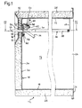
- the baking muffle 12 shown in Fig. 1 has an open to the front cuboid baking chamber 14, which is formed by a muffle wall 16 made of sheet metal is enclosed on five sides.
- the muffle wall 16 has a bottom wall 18, one Rear wall 20, a top wall 22 and side walls 24 and on the open front an edge flange 26 which cooperates with an oven door, not shown.
- the Bottom wall as well as the side walls 24 and the top wall 22 are of one Insulating mat 28 wrapped backwards by an insulating mat thickness over the rear wall 20 protrudes and extends forward to the rear of the edge flange 26 and by means of three wire loops around the whole muffle 12, not shown here is captured. Between the protruding edge areas of the insulating mat 28 an insulating mat 30 is fitted, which covers the entire rear wall 20 and only from There is glass wool that is exposed on both sides, i.e. is not covered with a film.
- the two parallel End sections 40 and 42 penetrate the rear wall 20 of the muffle wall 16 normally.
- the end portions 40 and 42 extend a little way over the rear Back plane of the insulating mat 30 the back and end with contact pins 44 and 46 for connecting electrical leads, not shown.
- the end portions 40 and 42 of the tubular heater 38 are adjacent the rear wall 20 passed through a connecting rectangular flat flange 48 made of sheet metal and soldered or welded to this flange 48.
- the flange 48 sits in one attached to the rear wall 20 bearing part 50.
- This has the shape of a horizontal extending profile strip that is slightly wider and slightly higher than the flange 48 and a vertical rear wall 52 has two on the back of it normally backwards extending bolts 54 and 56 are attached by suitable Grip through openings of the rear wall 20 of the muffle wall 18.
- a bearing extension 58 obliquely to the front angled above and forms together with the rear wall 52 a channel 60 in the the flange 48 is supported by the bearing shoulder 58 with its lower edge.
- the Flange by the weight of the radiator 36 from the inclined bearing shoulder 58 against the Back wall 52 pressed to fit as tightly as possible for a good seal.
- the front end of the radiator 36 is from an elastic hook 64 fastened to the top wall 22 which holds it engages below.
- the hook 64 is moved forward by the operator under the Radiator 36 pulled away.
- the tilted position of the radiator 36 is through broken lines indicated in Fig. 1.
- the upper area of the flange is effective 48 of the radiator 36 with a downward limiting limit Retaining lug 62 of the bearing part 50 together, which extends from the upper edge of the Back wall 52 of the bearing part first obliquely downwards and then in a hook-like manner Piece extends backwards downwards.
- the rear wall 20 of the muffle wall 18 has passage openings 66 and 68 and the Rear wall 52 of the bearing part 50 of the same size, so that aligned openings 70 and 72 each for an end section 40 or 42 of the tubular heater 38.
- This Through openings are about twice as wide as the end portions 40 and 42 of the Tubular heater 38 and have such a height that they in both folding positions of the radiator 36 still a distance of half a diameter of Have tubular radiator tube of this.
- the rear wall insulating mat 30 has a separating part in this area horizontal slot 74 in the form of a simple section through which the end portions 40 and 42 of the tubular heater 38 extend and at its average height in the operating position of the radiator 36 is.
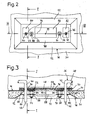
- the entire radiator leadthrough area is covered by a covering device 76 in Form of an embossed sheet metal part overlapped.
- This has a flat central area 78, the passage openings 80 and 82 for the end sections 40 and 42 of the radiator 36 owns. Seen horizontally, these are aligned with the lower areas Through openings 66 to 72 of the muffle wall 16 and the bearing part 50 are, however run slightly higher to the higher swivel deflections of the tubular heater 36 to consider this point.
- the middle area 78 of the covering device 76 has also suitable through openings for the bolts 54 and 56 of the bearing part 50.
- the bearing part 50 When assembling the device, the bearing part 50 is first together with the Radiator 36 placed on the rear wall 20 of the muffle wall 16 and on the other Screwed back by nuts 84 and 86, which are also spacers for the then represent cover device 76 placed on bolts 54 and 56.
- the cover device 76 is then fixed by nuts 88 and 90 against the nuts 84 and 86 screwed, the rear wall insulating mat 30 elastic in the lead-through area is compressed to a third of its original thickness.
- To damage to avoid the insulating mat 30 by making the transitions too sharp plate-like with an all around at an angle of about 30 ° to the rear extending peripheral edge 92.
- the radiator has another Tubular heating element, which is in the same plane as the tubular heating element 38 and within this is arranged and two lying between the end portions 40 and 42 Has end sections. These also penetrate the flange and are fixed with connected and can be next to each other, together by one central through openings 94 of the bearing part 50, a central through openings 96 of the Muffle wall 16, through the slot 74 of the rear wall insulating mat 30 and a central Extend passage openings 98 of the cover device 76. These central Through openings each have the same height as the ones next to them Passages for the tubular heater 38, but are three times as wide as this. On Earth contact pin 99 welded or soldered to the flange protrudes through the center of the central openings 94 to 98 and the slot 74 of the insulating mat 30 and is on its outer end connected to an earth connection line, not shown.
Landscapes
- Engineering & Computer Science (AREA)
- Chemical & Material Sciences (AREA)
- Combustion & Propulsion (AREA)
- Mechanical Engineering (AREA)
- General Engineering & Computer Science (AREA)
- Resistance Heating (AREA)
- Muffle Furnaces And Rotary Kilns (AREA)
- Electric Stoves And Ranges (AREA)
Abstract
Description
- Fig. 1
- zeigt einen vertikalen Schnitt durch die Backofenmuffel eines elektrischen Haushalts-Backofens im wesentlichen entlang den Linien I-I in den Figuren 2 und 3;
- Fig. 2
- ausschnittsweise eine Rückansicht der Backofenmuffel gemäß Fig. 1 im Bereich der Durchführung des Heizkörpers durch die Muffelwandung und
- Fig. 3
- ausschnittweise einen Schnitt im wesentlichen entlang den Linien III-III in den Figuren 1 und 2.
Claims (12)
- Backofenmuffel mit einem von einer Muffelwandung umschlossenen Backraum, in dem ein zu Reinigungszwecken verschwenkbar an der Muffel-wandung gehalterter Heizkörper angeordnet ist, der einen Durchlaß der Muffelwandung durchsetzt und außerhalb der Muffel Anschlüsse für die Energieversorgung aufweist, dadurch gekennzeichnet, dass eine an der Außenseite der Muffelwandung (16) angeordnete Isoliermatte (30) den Bereich des Durchlasses (66, 68, 96) übergreift und der Heizkörper einen engen Durchlaß (74) der Isoliermatte (30) durchsetzt und im Bereich des Durchlasses zwischen der Isoliermatte (30) und den Anschlüssen (44, 46) für die Energieversorgung des Heizkörpers (36) eine Abdeckeinrichtung (76) mit einem Durchlaß (80, 82, 98) für den Heizkörper (36) angeordnet ist.
- Backofenmuffel nach Anspruch 1, dadurch gekennzeichnet, dass die Isoliermatte (30) ein elastisches Material aufweist.
- Backofenmuffel nach Anspruch 2, dadurch gekennzeichnet, dass die Isoliermatte (30) einen sie durchsetzenden Abschnitt des Heizkörpers elastisch umschließt.
- Backofenmuffel nach Anspruch 3, dadurch gekennzeichnet, dass die Isoliermatte (30) als Durchlaß für den Heizkörper einen Schnitt (74) aufweist.
- Backofenmuffel nach einem der Ansprüche 2 bis 4, dadurch gekennzeichnet, dass die Isoliermatte (30) zwischen der Abdeckeinrichtung (76) und der Muffelwandung (16) elastisch zusammendrückt ist.
- Backofenmuffel nach Anspruch 5, dadurch gekennzeichnet, dass die Isoliermatte (30) etwa auf 20 bis 70 %, vorzugsweise 25 bis 55 % und insbesondere 33 % ihrer Dicke im entspannten Zustand zusammengedrückt ist.
- Backofenmuffel nach einem der Ansprüche 1 bis 6, dadurch gekennzeichnet, dass mit dem Heizkörper (36) ein im Backraum (14) angeordneter Flansch (48) fest verbunden ist, der in der Betriebsstellung des Heizkörpers (36) den Durchlaß (66, 68, 96) der Muffelwandung (16) verschließt.
- Backofenmuffel nach Anspruch 7, dadurch gekennzeichnet, dass zur Schwenkhalterung des Heizkörpers (36) an der Muffelwandung (16) nahe unterhalb der Durchlaßöffnung (66, 68, 96) eine Lagerinne (50, 60) angeordnet ist, in die der Flansch (48) als Lagerschneide eingreift.
- Backofenmuffel nach Anspruch 7 oder 8, dadurch gekennzeichnet, dass die Abdeckeinrichtung (76) die Isoliermatte (30) in der Betriebsstellung des Heizkörpers (36) gegen dessen Flansch (48) drückt.
- Backofenmuffel nach einem der Ansprüche 1 bis 9, dadurch gekennzeichnet, dass die Durchlässe (66, 68, 96, 80, 82, 98) der Muffelwandung (16) und der Abdeckeinrichtung (76) den Heizkörper (36) mit einem solchen Abstand umgeben, dass das Material der Isoliermatte (30) den durch Schwenkbewegungen des Heizkörpers (36) verursachten Relativbewegungen zwischen den Durchlässen und dem Heizkörper unter elastischer Verformung Stand hält.
- Backofenmuffel nach einem der Ansprüche 1 bis 10, dadurch gekennzeichnet, dass der Heizkörper (36) mindestens einen Rohrheizkörper (38) mit zwei Rohrendabschnitten (40, 42) umfasst und die Durchlässe (66, 68, 96, 80, 82, 98) der Muffelwandung (16) und der Abdeckeinrichtung (76) jeweils mindestens zwei Durchlaßöffnungen für die Rohrendabschnitte (40, 42) des Heizkörpers (36) aufweisen.
- Backofenmuffel nach einem der Ansprüche 1 bis 11, dadurch gekennzeichnet, dass die Abdeckeinrichtung (76) einen zur Muffelwandung (16) etwa parallelen mittleren Abschnitt (78) aufweist und abgewinkelte Randbereiche (92), die sich in einem spitzen Winkel von vorzugsweise weniger als etwa 50 Grad von dem benachbarten Bereich der Muffelwandung (16) wegerstrecken.
Applications Claiming Priority (2)
| Application Number | Priority Date | Filing Date | Title |
|---|---|---|---|
| DE10203615 | 2002-01-30 | ||
| DE10203615.2A DE10203615B4 (de) | 2002-01-30 | 2002-01-30 | Backofenmuffel |
Publications (2)
| Publication Number | Publication Date |
|---|---|
| EP1333229A2 true EP1333229A2 (de) | 2003-08-06 |
| EP1333229A3 EP1333229A3 (de) | 2004-11-10 |
Family
ID=7713407
Family Applications (1)
| Application Number | Title | Priority Date | Filing Date |
|---|---|---|---|
| EP03001732A Withdrawn EP1333229A3 (de) | 2002-01-30 | 2003-01-27 | Backofenmuffel |
Country Status (2)
| Country | Link |
|---|---|
| EP (1) | EP1333229A3 (de) |
| DE (1) | DE10203615B4 (de) |
Cited By (1)
| Publication number | Priority date | Publication date | Assignee | Title |
|---|---|---|---|---|
| ES2390022A1 (es) * | 2010-03-23 | 2012-11-06 | Bsh Electrodomésticos España, S.A. | Dispositivo de aparato de cocción. |
Citations (1)
| Publication number | Priority date | Publication date | Assignee | Title |
|---|---|---|---|---|
| US3899655A (en) | 1974-01-09 | 1975-08-12 | Electro Therm | Oven, heating element and socket assembly |
Family Cites Families (6)
| Publication number | Priority date | Publication date | Assignee | Title |
|---|---|---|---|---|
| GB636432A (en) * | 1948-01-03 | 1950-04-26 | Jackson Electric Stove Company | Improvements relating to electrically heated cooking ovens or the like |
| US3334215A (en) * | 1963-10-04 | 1967-08-01 | Gen Motors Corp | Domestic electrical appliance |
| US3296417A (en) * | 1964-07-31 | 1967-01-03 | Gen Electric | Hinging means for oven heating element |
| DE3723628A1 (de) * | 1987-07-17 | 1989-01-26 | Licentia Gmbh | Mikrowellenofen |
| DE4304099A1 (de) * | 1993-02-11 | 1994-08-18 | Bosch Siemens Hausgeraete | Backofenmuffel mit schwenkbar angeordnetem Heizkörper |
| DE19848874A1 (de) * | 1998-10-22 | 2000-04-27 | Bsh Bosch Siemens Hausgeraete | Backofen |
-
2002
- 2002-01-30 DE DE10203615.2A patent/DE10203615B4/de not_active Expired - Lifetime
-
2003
- 2003-01-27 EP EP03001732A patent/EP1333229A3/de not_active Withdrawn
Patent Citations (1)
| Publication number | Priority date | Publication date | Assignee | Title |
|---|---|---|---|---|
| US3899655A (en) | 1974-01-09 | 1975-08-12 | Electro Therm | Oven, heating element and socket assembly |
Cited By (1)
| Publication number | Priority date | Publication date | Assignee | Title |
|---|---|---|---|---|
| ES2390022A1 (es) * | 2010-03-23 | 2012-11-06 | Bsh Electrodomésticos España, S.A. | Dispositivo de aparato de cocción. |
Also Published As
| Publication number | Publication date |
|---|---|
| DE10203615B4 (de) | 2016-11-24 |
| DE10203615A1 (de) | 2003-07-31 |
| EP1333229A3 (de) | 2004-11-10 |
Similar Documents
| Publication | Publication Date | Title |
|---|---|---|
| DE2824628C2 (de) | Scheuerleistenheizkörper | |
| DE102009022608B4 (de) | Kraftstoffzufuhrvorrichtung | |
| EP0568755A1 (de) | Kontaktvorrichtung | |
| DE2825291A1 (de) | Klemme fuer elektrische leiter | |
| EP1376795B1 (de) | Vorrichtung zum Installieren von Energieleitungen | |
| DE2752194C2 (de) | ||
| CH686975A5 (de) | Fluidische Ventileinheit. | |
| DE3126013A1 (de) | Glaskeramik-kochfeld | |
| DE102011018962C5 (de) | Kochfeld mit zentraler Absaugung von Kochdünsten nach unten | |
| DE10203615B4 (de) | Backofenmuffel | |
| EP2876243B1 (de) | Schiebetor mit integrierter Flügeltür | |
| EP1308678B1 (de) | Lüftungseinrichtung | |
| DE102004012496B4 (de) | Kältegerät mit Türöffnungshilfe | |
| EP1681906B1 (de) | Abgedichteter Heizkörper | |
| DE3013489C2 (de) | Gehäuse für elektrische Geräte | |
| DE10225811A1 (de) | Mit einem verstellbaren Lamellengitter versehene Lüftungsdüse | |
| DE3128906A1 (de) | Lueftungsvorrichtung fuer raeume mit zwei getrennten stroemungswegen zur be- und entlueftung | |
| EP0436578B1 (de) | Behälter einer gasisolierten mittelspannungs-lastschaltanlage | |
| DE29804203U1 (de) | Schutzabdeckung für brandgefährdete elektrische Installationen | |
| DE112006000165T5 (de) | PTC-Stangenanordnung und Vorwärmer welcher eine solche umfasst | |
| DE3933972A1 (de) | Firstentlueftung | |
| CH658547A5 (de) | Batteriegehaeuse. | |
| DE4445625C2 (de) | Deckenluftauslaß mit einem Luftanschlußkasten | |
| CH719624B1 (de) | Heissluft-Gargerät mit Trennwand. | |
| DE3514707C2 (de) | Vorrichtung zur Dachentlüftung |
Legal Events
| Date | Code | Title | Description |
|---|---|---|---|
| PUAI | Public reference made under article 153(3) epc to a published international application that has entered the european phase |
Free format text: ORIGINAL CODE: 0009012 |
|
| AK | Designated contracting states |
Designated state(s): AT BE BG CH CY CZ DE DK EE ES FI FR GB GR HU IE IT LI LU MC NL PT SE SI SK TR |
|
| AX | Request for extension of the european patent |
Extension state: AL LT LV MK RO |
|
| RAP1 | Party data changed (applicant data changed or rights of an application transferred) |
Owner name: BSH BOSCH UND SIEMENS HAUSGERAETE GMBH |
|
| PUAL | Search report despatched |
Free format text: ORIGINAL CODE: 0009013 |
|
| AK | Designated contracting states |
Kind code of ref document: A3 Designated state(s): AT BE BG CH CY CZ DE DK EE ES FI FR GB GR HU IE IT LI LU MC NL PT SE SI SK TR |
|
| AX | Request for extension of the european patent |
Extension state: AL LT LV MK RO |
|
| 17P | Request for examination filed |
Effective date: 20050510 |
|
| AKX | Designation fees paid |
Designated state(s): AT BE BG CH CY CZ DE DK EE ES FI FR GB GR HU IE IT LI LU MC NL PT SE SI SK TR |
|
| 17Q | First examination report despatched |
Effective date: 20060116 |
|
| GRAP | Despatch of communication of intention to grant a patent |
Free format text: ORIGINAL CODE: EPIDOSNIGR1 |
|
| STAA | Information on the status of an ep patent application or granted ep patent |
Free format text: STATUS: THE APPLICATION IS DEEMED TO BE WITHDRAWN |
|
| 18D | Application deemed to be withdrawn |
Effective date: 20071130 |