EP1330659B1 - Method and device for dissolving hyperpolarised solid material for nmr analyses - Google Patents
Method and device for dissolving hyperpolarised solid material for nmr analyses Download PDFInfo
- Publication number
- EP1330659B1 EP1330659B1 EP01992900A EP01992900A EP1330659B1 EP 1330659 B1 EP1330659 B1 EP 1330659B1 EP 01992900 A EP01992900 A EP 01992900A EP 01992900 A EP01992900 A EP 01992900A EP 1330659 B1 EP1330659 B1 EP 1330659B1
- Authority
- EP
- European Patent Office
- Prior art keywords
- sample
- polarised
- dissolved
- dissolving
- accordance
- Prior art date
- Legal status (The legal status is an assumption and is not a legal conclusion. Google has not performed a legal analysis and makes no representation as to the accuracy of the status listed.)
- Expired - Lifetime
Links
- 238000000034 method Methods 0.000 title claims abstract description 37
- 239000011343 solid material Substances 0.000 title claims description 29
- 238000004458 analytical method Methods 0.000 title claims description 7
- 230000005291 magnetic effect Effects 0.000 claims abstract description 32
- 239000007787 solid Substances 0.000 claims abstract description 23
- 239000000463 material Substances 0.000 claims description 69
- 238000005481 NMR spectroscopy Methods 0.000 claims description 64
- 239000002904 solvent Substances 0.000 claims description 47
- 238000002156 mixing Methods 0.000 claims description 6
- 238000003756 stirring Methods 0.000 claims description 6
- 238000004519 manufacturing process Methods 0.000 claims description 5
- 238000002844 melting Methods 0.000 abstract 2
- 230000008018 melting Effects 0.000 abstract 2
- 239000013307 optical fiber Substances 0.000 abstract 1
- 239000000523 sample Substances 0.000 description 70
- 239000000243 solution Substances 0.000 description 25
- 239000001307 helium Substances 0.000 description 22
- 229910052734 helium Inorganic materials 0.000 description 22
- SWQJXJOGLNCZEY-UHFFFAOYSA-N helium atom Chemical compound [He] SWQJXJOGLNCZEY-UHFFFAOYSA-N 0.000 description 22
- 239000007788 liquid Substances 0.000 description 17
- 238000001514 detection method Methods 0.000 description 14
- 238000010438 heat treatment Methods 0.000 description 12
- 238000001816 cooling Methods 0.000 description 5
- 239000007789 gas Substances 0.000 description 5
- 239000007791 liquid phase Substances 0.000 description 5
- IJGRMHOSHXDMSA-UHFFFAOYSA-N Atomic nitrogen Chemical compound N#N IJGRMHOSHXDMSA-UHFFFAOYSA-N 0.000 description 4
- XLYOFNOQVPJJNP-ZSJDYOACSA-N Heavy water Chemical compound [2H]O[2H] XLYOFNOQVPJJNP-ZSJDYOACSA-N 0.000 description 4
- 239000011324 bead Substances 0.000 description 4
- 230000005540 biological transmission Effects 0.000 description 4
- 230000005284 excitation Effects 0.000 description 4
- 238000003384 imaging method Methods 0.000 description 4
- 238000011065 in-situ storage Methods 0.000 description 4
- XLYOFNOQVPJJNP-UHFFFAOYSA-N water Substances O XLYOFNOQVPJJNP-UHFFFAOYSA-N 0.000 description 4
- PEDCQBHIVMGVHV-UHFFFAOYSA-N Glycerine Chemical compound OCC(O)CO PEDCQBHIVMGVHV-UHFFFAOYSA-N 0.000 description 3
- 238000013019 agitation Methods 0.000 description 3
- 239000003990 capacitor Substances 0.000 description 3
- 230000001276 controlling effect Effects 0.000 description 3
- 238000013461 design Methods 0.000 description 3
- 238000001727 in vivo Methods 0.000 description 3
- 230000001678 irradiating effect Effects 0.000 description 3
- 238000002595 magnetic resonance imaging Methods 0.000 description 3
- 239000002245 particle Substances 0.000 description 3
- 239000000843 powder Substances 0.000 description 3
- 238000004611 spectroscopical analysis Methods 0.000 description 3
- 230000003068 static effect Effects 0.000 description 3
- 239000000126 substance Substances 0.000 description 3
- RYGMFSIKBFXOCR-UHFFFAOYSA-N Copper Chemical compound [Cu] RYGMFSIKBFXOCR-UHFFFAOYSA-N 0.000 description 2
- 229910052802 copper Inorganic materials 0.000 description 2
- 239000010949 copper Substances 0.000 description 2
- 238000013016 damping Methods 0.000 description 2
- 230000001419 dependent effect Effects 0.000 description 2
- 238000002059 diagnostic imaging Methods 0.000 description 2
- 239000006185 dispersion Substances 0.000 description 2
- 238000000338 in vitro Methods 0.000 description 2
- 238000005259 measurement Methods 0.000 description 2
- 229910052757 nitrogen Inorganic materials 0.000 description 2
- 238000013421 nuclear magnetic resonance imaging Methods 0.000 description 2
- 230000003287 optical effect Effects 0.000 description 2
- 239000012071 phase Substances 0.000 description 2
- 230000005855 radiation Effects 0.000 description 2
- 230000000717 retained effect Effects 0.000 description 2
- 230000035945 sensitivity Effects 0.000 description 2
- 239000007790 solid phase Substances 0.000 description 2
- 229910001220 stainless steel Inorganic materials 0.000 description 2
- 239000010935 stainless steel Substances 0.000 description 2
- 238000012546 transfer Methods 0.000 description 2
- QTBSBXVTEAMEQO-UHFFFAOYSA-M Acetate Chemical compound CC([O-])=O QTBSBXVTEAMEQO-UHFFFAOYSA-M 0.000 description 1
- 108010053481 Antifreeze Proteins Proteins 0.000 description 1
- 238000012935 Averaging Methods 0.000 description 1
- 229920002799 BoPET Polymers 0.000 description 1
- 229910001369 Brass Inorganic materials 0.000 description 1
- OKTJSMMVPCPJKN-UHFFFAOYSA-N Carbon Chemical compound [C] OKTJSMMVPCPJKN-UHFFFAOYSA-N 0.000 description 1
- 241000238366 Cephalopoda Species 0.000 description 1
- 239000005041 Mylar™ Substances 0.000 description 1
- 239000004696 Poly ether ether ketone Substances 0.000 description 1
- BQCADISMDOOEFD-UHFFFAOYSA-N Silver Chemical compound [Ag] BQCADISMDOOEFD-UHFFFAOYSA-N 0.000 description 1
- 239000004809 Teflon Substances 0.000 description 1
- YAINYZJQSQEGND-LBPDFUHNSA-N [1-(hydroxymethyl)cyclopropyl](113C)methanol Chemical compound O[13CH2]C1(CC1)CO YAINYZJQSQEGND-LBPDFUHNSA-N 0.000 description 1
- 238000010521 absorption reaction Methods 0.000 description 1
- 239000000654 additive Substances 0.000 description 1
- 239000004964 aerogel Substances 0.000 description 1
- 239000003570 air Substances 0.000 description 1
- 239000000538 analytical sample Substances 0.000 description 1
- 230000002528 anti-freeze Effects 0.000 description 1
- 238000013459 approach Methods 0.000 description 1
- JUPQTSLXMOCDHR-UHFFFAOYSA-N benzene-1,4-diol;bis(4-fluorophenyl)methanone Chemical compound OC1=CC=C(O)C=C1.C1=CC(F)=CC=C1C(=O)C1=CC=C(F)C=C1 JUPQTSLXMOCDHR-UHFFFAOYSA-N 0.000 description 1
- 239000006177 biological buffer Substances 0.000 description 1
- 238000009529 body temperature measurement Methods 0.000 description 1
- 238000009835 boiling Methods 0.000 description 1
- 239000010951 brass Substances 0.000 description 1
- 230000005587 bubbling Effects 0.000 description 1
- 229910052799 carbon Inorganic materials 0.000 description 1
- 239000000919 ceramic Substances 0.000 description 1
- 229910010293 ceramic material Inorganic materials 0.000 description 1
- 239000003795 chemical substances by application Substances 0.000 description 1
- 150000001875 compounds Chemical class 0.000 description 1
- 239000012611 container material Substances 0.000 description 1
- 239000002872 contrast media Substances 0.000 description 1
- 239000002826 coolant Substances 0.000 description 1
- 238000007405 data analysis Methods 0.000 description 1
- 238000012631 diagnostic technique Methods 0.000 description 1
- 238000005516 engineering process Methods 0.000 description 1
- 238000011049 filling Methods 0.000 description 1
- 239000012530 fluid Substances 0.000 description 1
- 238000007710 freezing Methods 0.000 description 1
- 230000008014 freezing Effects 0.000 description 1
- 239000012216 imaging agent Substances 0.000 description 1
- 238000010348 incorporation Methods 0.000 description 1
- 238000002347 injection Methods 0.000 description 1
- 239000007924 injection Substances 0.000 description 1
- 239000003562 lightweight material Substances 0.000 description 1
- 238000011068 loading method Methods 0.000 description 1
- 239000000696 magnetic material Substances 0.000 description 1
- 239000000203 mixture Substances 0.000 description 1
- 230000005298 paramagnetic effect Effects 0.000 description 1
- 239000010451 perlite Substances 0.000 description 1
- 239000004033 plastic Substances 0.000 description 1
- 229920003023 plastic Polymers 0.000 description 1
- 229920002530 polyetherether ketone Polymers 0.000 description 1
- 239000004810 polytetrafluoroethylene Substances 0.000 description 1
- 229920001343 polytetrafluoroethylene Polymers 0.000 description 1
- 229920002635 polyurethane Polymers 0.000 description 1
- 239000004814 polyurethane Substances 0.000 description 1
- 239000011148 porous material Substances 0.000 description 1
- 230000001105 regulatory effect Effects 0.000 description 1
- 229910052709 silver Inorganic materials 0.000 description 1
- 239000004332 silver Substances 0.000 description 1
- 238000007711 solidification Methods 0.000 description 1
- 230000008023 solidification Effects 0.000 description 1
- 238000000527 sonication Methods 0.000 description 1
- 241000894007 species Species 0.000 description 1
- 230000003595 spectral effect Effects 0.000 description 1
- 238000001228 spectrum Methods 0.000 description 1
- 238000004804 winding Methods 0.000 description 1
Images



Classifications
-
- A—HUMAN NECESSITIES
- A61—MEDICAL OR VETERINARY SCIENCE; HYGIENE
- A61B—DIAGNOSIS; SURGERY; IDENTIFICATION
- A61B5/00—Measuring for diagnostic purposes; Identification of persons
- A61B5/05—Detecting, measuring or recording for diagnosis by means of electric currents or magnetic fields; Measuring using microwaves or radio waves
- A61B5/055—Detecting, measuring or recording for diagnosis by means of electric currents or magnetic fields; Measuring using microwaves or radio waves involving electronic [EMR] or nuclear [NMR] magnetic resonance, e.g. magnetic resonance imaging
-
- G—PHYSICS
- G01—MEASURING; TESTING
- G01R—MEASURING ELECTRIC VARIABLES; MEASURING MAGNETIC VARIABLES
- G01R33/00—Arrangements or instruments for measuring magnetic variables
- G01R33/20—Arrangements or instruments for measuring magnetic variables involving magnetic resonance
- G01R33/28—Details of apparatus provided for in groups G01R33/44 - G01R33/64
- G01R33/282—Means specially adapted for hyperpolarisation or for hyperpolarised contrast agents, e.g. for the generation of hyperpolarised gases using optical pumping cells, for storing hyperpolarised contrast agents or for the determination of the polarisation of a hyperpolarised contrast agent
-
- G—PHYSICS
- G01—MEASURING; TESTING
- G01N—INVESTIGATING OR ANALYSING MATERIALS BY DETERMINING THEIR CHEMICAL OR PHYSICAL PROPERTIES
- G01N1/00—Sampling; Preparing specimens for investigation
- G01N1/28—Preparing specimens for investigation including physical details of (bio-)chemical methods covered elsewhere, e.g. G01N33/50, C12Q
- G01N1/44—Sample treatment involving radiation, e.g. heat
-
- G—PHYSICS
- G01—MEASURING; TESTING
- G01R—MEASURING ELECTRIC VARIABLES; MEASURING MAGNETIC VARIABLES
- G01R33/00—Arrangements or instruments for measuring magnetic variables
- G01R33/20—Arrangements or instruments for measuring magnetic variables involving magnetic resonance
- G01R33/28—Details of apparatus provided for in groups G01R33/44 - G01R33/64
- G01R33/30—Sample handling arrangements, e.g. sample cells, spinning mechanisms
- G01R33/307—Sample handling arrangements, e.g. sample cells, spinning mechanisms specially adapted for moving the sample relative to the MR system, e.g. spinning mechanisms, flow cells or means for positioning the sample inside a spectrometer
-
- G—PHYSICS
- G01—MEASURING; TESTING
- G01R—MEASURING ELECTRIC VARIABLES; MEASURING MAGNETIC VARIABLES
- G01R33/00—Arrangements or instruments for measuring magnetic variables
- G01R33/20—Arrangements or instruments for measuring magnetic variables involving magnetic resonance
- G01R33/44—Arrangements or instruments for measuring magnetic variables involving magnetic resonance using nuclear magnetic resonance [NMR]
- G01R33/48—NMR imaging systems
- G01R33/54—Signal processing systems, e.g. using pulse sequences ; Generation or control of pulse sequences; Operator console
- G01R33/56—Image enhancement or correction, e.g. subtraction or averaging techniques, e.g. improvement of signal-to-noise ratio and resolution
- G01R33/5601—Image enhancement or correction, e.g. subtraction or averaging techniques, e.g. improvement of signal-to-noise ratio and resolution involving use of a contrast agent for contrast manipulation, e.g. a paramagnetic, super-paramagnetic, ferromagnetic or hyperpolarised contrast agent
-
- G—PHYSICS
- G01—MEASURING; TESTING
- G01R—MEASURING ELECTRIC VARIABLES; MEASURING MAGNETIC VARIABLES
- G01R33/00—Arrangements or instruments for measuring magnetic variables
- G01R33/20—Arrangements or instruments for measuring magnetic variables involving magnetic resonance
- G01R33/62—Arrangements or instruments for measuring magnetic variables involving magnetic resonance using double resonance
Definitions
- the present invention relates to a device and method for dissolving solid polarised materials while retaining a high level of polarisation.
- the present invention relates to nuclear magnetic resonance (NMR) analysis, particularly to nuclear magnetic resonance imaging (MRI) and analytical high-resolution NMR spectroscopy.
- NMR nuclear magnetic resonance
- MRI nuclear magnetic resonance imaging
- X-rays potentially harmful radiation
- Analytical high resolution NMR spectroscopy is routinely used in the determination of molecular structure.
- MRI and NMR spectroscopy lack sensitivity due to the normally very low polarisation of the nuclear spins of the materials used.
- hyperpolarisation techniques in order to exploit the NMR signal for in vivo medical imaging the polarised material has to be brought into solution or liquid phase before being introduced into the imaging object.
- a problem exists in that the polarised solid material has to be brought into solution or liquid phase and transferred into the NMR magnet with a minimal loss of polarisation.
- WO9935508 (disclosing a device according to the preamble of claim 1) mentions a method for dissolving solid polarised material.
- the polarised material was manually lifted out of the cryostat and within about 1 second dissolved in deuterium oxide at 40°C while being subjected to a magnetic field of 0.4 T.
- This method enhanced the polarisation by a factor of up to 21 compared to other methods of producing a solution containing polarised material.
- This method has the disadvantage that as the sample is moved manually it is difficult to get reproducible results.
- the purpose of the present invention is to provide methods and devices for improving the prior art method for producing a solution containing polarised material.
- the present invention provides a method and means for bringing polarised solid material from a polarising unit into solution or liquid phase with a minimal loss of polarisation.
- Devices and methods for producing solutions of dissolved hyperpolarised materials e.g. contrast agents or analytical samples, are described.
- a polarising device and a dissolving device are combined in a single instrument, so that the transport time between being polarised and dissolved is minimised and the loss of polarisation of the sample is minimised.
- the polarising unit and the dissolving chamber is combined with a NMR spectrometer and/or NMR imager so that the time between the sample being dissolved and analysed is minimised and the loss of polarisation of the sample is minimised.
- polarisation may be achieved by use of a polarising agent, e.g. a compound comprising paramagnetic organic free radicals-
- the NMR data obtained by the use of devices and methods in accordance with the present invention may be NMR imaging data and/or NMR spectroscopy data.
- a solid sample of the material to be polarised is polarised while still in the solid phase by dynamic nuclear polarisation, while being maintained at a low temperature (e.g. under 100 K) in a strong magnetic field (e.g.1-25 T). After the solid material has been polarised, it is brought into solution with a minimum loss of polarisation.
- unit for dissolved polarised material will be considered to mean the following: a container in which dissolved polarised material can be stored.
- dissolved means that the molecules of a substance said to be dissolved in a solvent are homogeneously distributed in said solvent.
- the dissolving takes place in the same apparatus that contains the polarisation device.
- the solution of polarised material is made and used while retained in a combined polarisation, dissolving and NMR analysis device.
- material is polarised in a polarising apparatus in close proximity to a NMR spectrometer, the polarised material is dissolved in the polarising apparatus and then quickly transferred to the analysis region of the NMR spectrometer.
- the advantage of the described invention is that it provides means for bringing polarised solid material into solution with minimal loss ofpolarisation in a repeatable manner. This is crucial to the use of the solid state hyperpolarisation techniques in medical imaging and analytical in vitro high-resolution NMR spectroscopy. In solution, the NMR lines are narrow. This improves considerably the signal-to-noise ratio and spectral resolution, and also gives technical advantages since the sample does not have to be spun as for solid samples.
- the relaxation rate (loss of polarisation if hyperpolarised) increases rapidly as a function of inverse field strength. Therefore, for these polarised materials it is preferable that they are kept in a strong magnetic field (e.g. greater than 0.1 T) while being handled. Other reasons for the loss of polarisation are also known, e.g. sudden changes of magnetic field orientation, strong magnetic gradients, or radio frequency fields, and these should be avoided as much as possible.
- the dissolving of the polarised material can be promoted by several methods. When possible, the solid material should be provided as a finely divided powder in order to allow fast dispersion and intimate contact of the solid particles and the solvent.
- the solid particles (or beads) and solvent can be vigorously agitated by stirring, mixing, shaking, bubbling, crushing, sonication, microwave heating, laser irradiation or any other means that will provide agitation, and optionally, heating.
- the temperature of the solvent can be optimised for the particular material in order to provide the fastest possible dissolving without causing unnecessary relaxation.
- the relaxation rate as a function of temperature and field is unique to every solid material and solvent/solute system. It is therefore also advantageous when the temperature of the solvent is optimised for minimal relaxation of the actual material being dissolved.
- the magnetic field should be as strong as possible. This also applies to the liquid sample during the process of dissolving.
- the minimum T 1 during the process will generally increase with increasing magnetic field.
- a device for dissolving a solid polarised material is provided in a dynamic nuclear polarisation (DNP) system.
- This DNP system comprises a magnet with field strength of 0.1-25 T or more that is placed in a low loss cryostat in order to achieve optimal cryogenic hold times.
- the magnet may be superconducting.
- An especially preferred DNP system consists of a superconducting magnet designed for a field-strength of 2-25T. The magnet is placed in an ultra low loss cryostat to achieve optimal cryogenic hold time.
- the field homogeneity required is sample dependent, but will typically have to be +/-0.2mT over the sample volume.
- the magnet is designed to accommodate a low temperature space to cool the sample.
- the preferred superconducting magnet cryostat is preferably provided with a pumped helium bath or at least a cold space in the bore of the magnet.
- the helium bath may be contained in a tube that is thermally insulated (e.g. vacuum insulated) from the magnet helium reservoir but connected to it by a capillary to allow filling from the magnet reservoir.
- the low temperature space may simply be a cylinder (made from thin-walled stainless steel or copper or another non-magnetic material or combinations thereof) with the lower end closed.
- the low temperature space is preferably placed in vacuum inside the helium can of the superconducting magnet and the low temperature cylinder can preferably be thermally anchored at appropriate places in the bore, for example to the helium vapour-cooled shield and the liquid nitrogen-cooled shield or the like.
- the low temperature cylinder can preferably be connected to the helium can through a capillary at its base.
- the flow of helium may be controlled by a needle valve regulated from exterior, manually or automatically by computer control means or the like.
- the flow of helium into the helium bath may be controlled by a motorised needle valve.
- the level of the liquid can be monitored, e.g. by an Allen Bradley carbon resistor meter, and the needle valve controlled manually or automatically to maintain a fixed level.
- the bath can be pumped and the temperature of the bath can be ascertained through the helium vapour pressure measured, for example, by an absolute capacitance transducer or Pirani element. If cooled by gas then a temperature measurement can be used to control the needle valve.
- the cryogen e.g. helium or nitrogen, could also be supplied from an external reservoir.
- the sample is polarised by microwave irradiation at the proper frequency.
- a microwave arrangement is provided for irradiation.
- the microwave arrangement can be implemented in a number of ways. For lower frequencies (less than ca. 200 GHz) a wave-guide may be used to guide the waves to the sample space. At higher frequencies quasi-optical methods can be employed.
- the sample space is preferably constructed as a resonant microwave structure.
- the microwave structure is preferably configured to allow easy placement and exchange of samples and an efficient cooling of samples. Once polarised the sample is dissolved by means of a device and method in accordance with the present invention as described below.
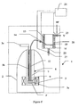
- dissolving of the hyperpolarised material in the sample-retaining cup 9 can be performed while the material is still inside the cryostat device 1.
- This can be achieved by providing a solvent introducing means.
- This can, for example, be achieved by supplying a suitable highpressure gas or fluid HP, e.g. air or helium or solvent, to valve 23 as shown by dotted lines in figure 1.
- a solvent can be added to the sample-retaining cup 9 by simply injecting the solvent into the open upper end of sample-transporting tube 7.
- the solution of solvent and dissolved polarised material can then be aspirated in any suitable manner, or the solution can be ejected through an outlet by injecting more solvent or a gas or the like.
- the polarised solid material When the polarised solid material is brought into solution phase inside the polarising unit by introducing the solvent into the polarising unit according to the present invention, the polarised solid material is dissolved while kept in the strong magnetic field of the polarising unit or close to the strong magnetic field area of the magnet. If the material is polarised in a helium (or nitrogen) bath, the material can be raised from the bath to drain the liquid coolant prior to dissolving. The sample would still experience a significant part of the magnetic field of the polarising unit.
- the solvent can then be introduced into the sample retaining cup and mixed with the solid material to rapidly dissolve the solid after which the solution could be extracted with a syringe (either manually or automatically) or by a flow system as described above and injected into the item being imaged or simply directly analysed by solution NMR.
- the amount of solvent added should have a mass and specific heat capacity such that it has enough thermal energy to prevent it from freezing when it is dissolving the solid material.
- Water is a good choice of solvent due to its high specific heat capacity and high latent energy of solidification. It is also the solvent of choice for biological reasons when the sample is to be used in vivo.
- Other suitable solvents are biological buffers such as Ringer's acetate.
- Tubes can also be silvered or coated with an insulating film (for example aluminised Mylar TM). It can also be advantageous to include a wrapping of resistive heating wire or film on the tubing to improve the means of controlling the temperature of the sample.
- insulating film for example aluminised Mylar TM.
- resistive heating wire or film is another factor to take into account. Another factor to take into account is the material used for manufacturing the sample-transporting tube and any sample holder used. The same criteria for choice of material as above applies here but ceramic materials can be especially suitable here.
- a ceramic or foamy plastic material that is porous to the extent that superfluid helium easily can circulate through the walls of the sample receiving tube and/or sample holder to cool the solid material while liquid water or other solvents cannot circulate through the walls.
- the analytical NMR instrument in the same instrument as the polarising unit and dissolving unit.
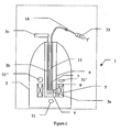
- FIG 2 where there is a plurality of analysis coils 31-31 ", i.e. nuclear magnetic resonance imaging coils and/or nuclear magnetic resonance spectroscopy coils. Coils which can be used for field shimming and NMR signal acquisition can be placed in positions that are known from high resolution analytical NMR
- the unit for dissolved polarised material is the same as the sample-retainer cup, and the transport time is zero seconds. This is advantageous, as in this case there is no need to move the sample out of the magnetic field of the superconducting magnet when performing the analysis i.e. imaging or spectroscopy.
- the low operating temperature of the coils immersed in liquid helium improves their signal to noise ratio by a significant factor (of more than 3).
- the requirements concerning field strength may not be identical for the polarisation and the NMR detection, and means may be provided for moving a sample from one part of the magnet to another.
- the NMR detection could advantageously be done at a lower or higher field than optimal for the DNP process.
- One implementation would therefore be that the DNP polarisation is done in cold helium gas at the lower edge of the magnet (i.e. in a lower field, e.g. 3.35 T). The field would then have to be shimmed in this area to the required homogeneity.
- the sample could then be lifted to the magnet centre (that has a higher field, e.g. 9.4 T, and homogeneity) for dissolving and NMR detection. Furthermore, the sample could be lifted to an intermediate place for dissolving and then moved to the magnet centre for NMR detection.
- the magnet centre that has a higher field, e.g. 9.4 T, and homogeneity
- a conceivable variation of the invention is the incorporation of a multiple sample holder into the device so that several samples can be polarised at once or sequentially and either ejected or dissolved one by one. It is also conceivable to use a system where several samples are dissolved and analysed simultaneously. As is obvious to the skilled person, a multiple sample holder system can be fashioned in many different ways e.g. using a carousel type holder or a grid-type holder.
- any ordinary NMR magnet that has a suitably wide bore size may be equipped with a flow cryostat and instrumentation as described below in order to enabling the production of solutions of molecules with DNP enhanced nuclear polarisation.
- a flow cryostat is a vacuum insulated chamber that may be inserted into the bore of a magnet normally designed to have a room temperature bore, thereby allowing the temperature of the bore to be lowered by a stream of a cold cryogen.
- the flow cryostat is usually connected to an external cryogen supply through a transfer line and the flow of cryogen into the flow cryostat cools the bore of the magnet and forms a low temperature space.
- the flow cryostat may be equipped with means, described below, to enable the polarisation of solid materials by DNP and it may be equipped with instrumentation, described below, for the detection of nuclear signals in the solid state and in solution. Note that in dedicated DNP systems for NMR analysis or production of hyperpolarised imaging agents the low temperature space is preferably integrated into the magnet cryostat.
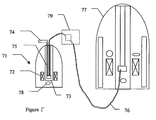
- a DNP device which performs the present invention in an in situ approach (i.e. the polarisation, dissolving and NMR detection are both performed in the same instrument). It has the disadvantage that existing NMR spectrometers cannot easily be reconfigured for DNP enhanced spectroscopy.
- a DNP device 71 comprising a magnetic field-generating unit 72, e.g.
- superconducting magnet, permanent magnet or electromagnet provided with an internal cold space 73 where a sample can be positioned and where a microwave-generating unit consisting of a microwave source 74 and a wave guide arrangement 75, can be present in order to polarise the sample, is arranged in proximity to and connectable by a polarised material transfer line 76 to a NMR spectrometer 77.
- Further NMR coils 78 may optionally be present in the DNP unit in order to quantify the magnetisation of the sample in the solid state and/or in solution).
- the polarised sample is dissolved in situ as described above (79 is a unit for polarised material).
- the advantage of this configuration is that it can be provided as an upgrade for existing NMR spectrometers.
- the reconfiguration of the NMR spectrometer for DNP hyperpolarisation is quick and easy.
- Existing NMR probes flow probes
- the polarised liquid sample should leave the DNP apparatus as quickly as possible and be positioned in the flow probe active region for immediate NMR analysis and therefore accurate timing of the entire polarisation, dissolving, transporting process and triggering of the NMR excitation/acquisition once the sample is in the NMR spectrometer is required.
- This may conveniently be computer controlled in order to ensure that the transit time for the liquid and the delay between its arrival in the NMR spectrometer and the triggering of the NMR excitation/acquisition is preferably shorter than the nuclear T 1 .
- FIG 3 shows schematically a cross-section through a solvent heating and injecting device 41 suitable for injecting heated solvent into a sample-retaining container, e.g. a sample-retaining cup in a cryostat.
- Solvent heating and injecting device 41 comprises a pressure container 43, capable of resisting pressures of at least 2 x 10 5 Pa (2 bar), and preferably 10 6 Pa (10 bar), which pressure container 43 can be heated by heating means such as heating coil 45 wrapped around pressure container 43 and connectable via a switch or relay 46 to a power supply 47.
- Pressure container 43 is preferably thermally insulated, for example by an insulating jacket 49 that surrounds it.
- Pressure container 43 is provided with an inlet 51, connectable via an inlet pipe 53 and inlet valve 55 to a supply of solvent 57, and an outlet 59 connectable via an outlet pipe 61 and outlet valve 63 to a sample-retaining container (not shown).
- a pressure sensing device such as a pressure transducer 65 is connectable to solvent heating and injecting device 41 in order to measure, and optionally display, the pressure in pressure container 43.
- the solvent heating and injecting device 41 works in the following way:
- a sample holder and a suitable microwave structure may be placed in the cold space in order to achieve microwave irradiation of the sample.
- the microwave structure can be a horn antenna or a chamber attached to the end of a wave-guide (as shown in figure 4) or a set of Fabry-Perot mirrors or any other suitable microwave irradiating structures.
- the microwave structure is preferably designed to act as a resonance chamber for microwaves in order to increase the strength of the microwave field in the microwave structure.
- wave-guides may conveniently be used to guide the waves to the irradiating structure.
- the geometry and dimensions of the wave-guide are chosen in order to reduce microwave losses.
- the wave-guide is designed to have as low a heat load to the low temperature space as possible, and can be made, for example, from silver plated thin-walled stainless steel. Corrugated wave-guides could also be used. At higher frequencies quasi-optical methods can be employed, and the microwave can be guided with lenses and mirrors.
- the microwave structure preferably has openings to allow an easy exchange of sample and efficient cooling of the sample.
- a suitable microwave oscillator generates the microwaves, e.g. an IMPATT diode oscillator, or an IMPATT amplified Gunn oscillator, or a BWO or the like.
- the microwave oscillator may be an integrated part of the resonant structure for irradiating the sample.
- the active device producing the microwaves may be physically placed in the magnet close to the sample whereby transmission losses would be reduced.
- FIG 4 shows a perspective view of part of an embodiment of a polarising means 3 intended to be placed inside the cryostat of a DNP system.
- This comprises a microwave chamber 3a connected by a wave-guide 3b to a source of microwave energy (not shown).
- Chamber 3a has a substantially cylindrical outer wall 3d, an upper end plate 3e and a lower end plate 3f.
- Chamber 3a is made of a microwave reflecting material such as brass.
- Upper end plate 3e has a central circular opening 3g with a diameter adapted to allow a sample-retaining cup 9 (not shown) to pass into the chamber 3a.
- Upper and lower end plates 3e, 3f have a plurality of cut-outs 3h which are covered by a microwave reflecting mesh 3i which allows liquid helium to enter the chamber 3a while preventing microwaves from leaving the chamber 3a through the cut-outs 3h.
- the chamber 3a is mounted on the lower end 3j of the wave-guide 3b and a slot 3k in the wall 3d of the chamber 3a is aligned with a similar slot 31 in the lower end 3j of the wave-guide 3b in order to allow microwaves to pass from the wave guide 3b into the chamber 3a.
- the dimensions of the slots 3k, 31 are adapted to optimise the flow of microwaves into the chamber 3 a.
- the slots can be 5-10 mm high and 2-7 mm wide.
- the lower end 3j of the wave-guide 3b is tapered towards the bottom in order to act as a microwave reflector for increasing the amount of microwave energy coupled into the chamber 3a. Suitable angles of taper depend on the dimensions of the wave-guide, the microwave frequency used and the dimensions of the slots 31, 31, but can be from about 5° to 60°, but preferably from 15° to 30°.
- the dimensions of the chamber 3a, wave-guide 3b, slots 3k, 31 are adapted so that chamber 3a acts as a resonance chamber for the microwave energy.
- the chamber can be optionally provided with a central NMR pick-up coil 51.
- a central NMR pick-up coil 51 This can be suitably made of a cylinder 53 made of PTFE provided with, depending on the static field orientation, helical or saddle shaped copper windings (not shown) and connected to suitable sensing means.
- a sample is placed in a sample-retaining cup 9 and the sample retaining container is lowered into the centre of the chamber 3a (inside the pickup coil if there is a pick up coil).
- the source of microwave radiation is activated and the sample irradiated. It can then be dissolved in situ in the cryostat and the dissolved polarised sample held in the unit for dissolved polarised material, or some other container (e.g. the sample retaining cup) in a strong magnetic field, until needed.
- the lower end plate 3f of the chamber may have a central hole 3m of the same diameter as a sample-retaining cup 9. This allows the sample-retaining cup 9 to be lowered through the chamber 3a and out the bottom of it.
- a sample-receiving container could be provided with a plurality of vertically separated sample-retaining cups. These cups could each be the height of the chamber 3a or a fraction thereof. If they are the same height as the chamber 3a then it would be possible to expose a first sample in one cup to microwaves in the chamber 3a while a second sample in a second cup is positioned outside the chamber, but still very close to the strong magnetic field.
- the sample receiving container can be moved vertically so that the second sample in the second cup is inside the chamber 3a and the polarised first sample in the first cup is maintained polarised in the magnetic field outside the chamber 3a. This can be repeated until all the samples have been polarised, then all the samples can be dissolved at once, using one device, or a plurality of devices, for extracting material from the sample-transporting tube.
- each polarised sample could be dissolved in turn and either stored in the liquid phase in its cup (which is therefore a unit for dissolved polarised material) in the strong magnetic field in the DNP unit or in another unit for dissolved polarised material in the magnetic field of an imaging or spectrometry device.
- NMR detection is particular desirable for analytical applications. For other applications NMR detection optionally provides a measure of the nuclear polarisation.
- the NMR detection coil could be of any known design, e.g. solenoid or saddle shaped. Usually the coil (inductance) is tuned to the NMR frequency with a capacitor and matched to the characteristic impedance of the cabling. The NMR coil could be tuned and matched at a number of frequencies in order to detect the nuclei of interest.
- the capacitors could be mounted close to the coil in the cold space. This would allow the highest Q-values to be obtained. In the event that it is impractical to have the capacitors close to the coil, then they may be put outside the cold space and connected to the low temperature space via a transmission line.
- the transmission line could be coaxial, twisted pair, stripline, or any other suitable cabling.
- the choice will be a compromise between heat load to the cold space and signal attenuation.
- Several coils could also be envisaged. They could be tuned for two NMR frequencies and would allow double resonance NMR (decoupling, cross polarisation, etc) to be performed in both solid state and liquid phase. This would also allow simultaneous detection of nuclei of more than one nuclear species. The spectrometer would then have to have multiple receivers.
- the NMR signal of the various nuclei could be acquired sequentially.
- a sample-carousal for moving samples may be provided.
- the dissolving of the solid material may be detected by optical means, as in order to perform reproducible NMR analysis it is important that the material to be examined is dissolved homogeneously. This may be checked by using optional optical photodetection means inside or outside the NMR analytical chamber. Since some of the nuclei of interest may have very short T 1 values it can be important to secure analysis as soon as the dissolving process is finished. It is therefore preferable to have means arranged for coincident excitation/detection of all nuclei of interest. If the NMR detection circuit is cooled then a better signal-to-noise ratio is obtained. Furthermore, cooling of the signal amplifier is often advantageous. Consequently the signal amplifier may be positioned close to the NMR detection circuit and preferably in the cold space. Superconducting coils and SQUID detectors are other devices that are available to improve the signal-to-noise ratio.
- the device is a simple radio frequency magnetic resonance spectrometer. Such a device can be used to determine the polarisation of the solid sample material before it is dissolved and uses any of the previous described detection coils.
- the RF circuit consists of a VCO (voltage controlled oscillator) 81, a directional coupler 83, a 180-degree hybrid 85, a mixer 87, a LNA (low noise amplifier) 89, a low pass filter 91, a PC data acquisition card 93, and tuned and matched MR (or excitation) coils 95 (giving magnetic field B 1 ) arranged to provide a nearly uniform field transverse to the direction of the static field B 0 from static field coils 97.
- the coils 95 are tuned to the MR frequency and matched to the characteristic impedance of the transmission line (e.g. 50 ⁇ ).
- the VCO 81 (or function generator) generates a continuous wave signal that is split by directional coupler 83 (divider) into two signals, which drives the local oscillator of the mixer 87 and the other to 180-degree hybrid 85 feeding the MR coil 95.
- Fixed attenuators (not shown) may be used to adjust the signal levels.
- the VCO 81 should be capable of being frequency modulated over a sufficient frequency range to cover the spectra range of interest.
- the modulation rate could be typically 5-50Hz, and the modulation signal is supplied synchronously with the signal acquisition (signal averaging).
- the modulation-signal and signal acquisition is generated from a PC data acquisition card 93, and the signal is conveniently available for further data analysis.
- a change of reflection coefficient is observed as the frequency is swept through the magnetic resonance.
- the reflection signal is amplified by the LNA 89 and fed to the mixer 87.
- an absorption or dispersion signal can be chosen.
- the bandwidth of the MR coils 95 in itself produces a parabolic baseline, which has to be subtracted from the signal.
- the baseline can be acquired before introducing the sample or it can be fitted with a polynomial function (or a spline function) outside the signal regions.
- the coil bandwidth can be adjusted for optimal performance in a number of ways, e.g. resistive damping, overcoupling which gives a better result, or, preferably, by actively loading the coils 95 with the LNA 89.
- the natural bandwidth of a tuned coil in this frequency regime is several hundred Hz, providing insufficient bandwidth for most applications. Resistive damping increases the useful bandwidth to an acceptable degree. However, this compromises the signal-to-noise ratio by the square root of the increase. This is acceptable to some extent since amplitude and phase-noise of the VCO often determine the signal-to-noise ratio.
- the magnetic field could be anything from a few mT to many T depending on the gyromagnetic ratio of the spin and the frequency of the VCO 81.
- the presence of a strong magnetic field, and, optionally, elevated/optimised solvent temperature, agitation, and a finely divided solid sample minimises the polarisation loss during dissolving.
- the amount of polarisation retained during the dissolving of any particular solid polarised material depends on, amongst others, the following factors: the composition of the polarised material, the form and size of the material (e.g. whether it is in the form of beads, powder, particles, or is present as a solid mass) the solvent used to dissolve it, the solvent temperature, the speed of dissolving, the magnetic field the dissolving takes place in.
Landscapes
- Physics & Mathematics (AREA)
- Health & Medical Sciences (AREA)
- Life Sciences & Earth Sciences (AREA)
- Condensed Matter Physics & Semiconductors (AREA)
- General Physics & Mathematics (AREA)
- Nuclear Medicine, Radiotherapy & Molecular Imaging (AREA)
- Animal Behavior & Ethology (AREA)
- Veterinary Medicine (AREA)
- Biophysics (AREA)
- Pathology (AREA)
- Engineering & Computer Science (AREA)
- Biomedical Technology (AREA)
- Heart & Thoracic Surgery (AREA)
- Medical Informatics (AREA)
- Molecular Biology (AREA)
- Surgery (AREA)
- High Energy & Nuclear Physics (AREA)
- General Health & Medical Sciences (AREA)
- Public Health (AREA)
- Radiology & Medical Imaging (AREA)
- Magnetic Resonance Imaging Apparatus (AREA)
- Sampling And Sample Adjustment (AREA)
- Investigating Or Analyzing Materials By The Use Of Magnetic Means (AREA)
- Inorganic Compounds Of Heavy Metals (AREA)
- Soft Magnetic Materials (AREA)
- Saccharide Compounds (AREA)
- Medicines Containing Antibodies Or Antigens For Use As Internal Diagnostic Agents (AREA)
- Analysing Materials By The Use Of Radiation (AREA)
- Spectrometry And Color Measurement (AREA)
- Investigating Or Analysing Materials By Optical Means (AREA)
- Measurement And Recording Of Electrical Phenomena And Electrical Characteristics Of The Living Body (AREA)
- Complex Calculations (AREA)
- Physical Or Chemical Processes And Apparatus (AREA)
- Polarising Elements (AREA)
Applications Claiming Priority (5)
| Application Number | Priority Date | Filing Date | Title |
|---|---|---|---|
| SE0004034 | 2000-11-03 | ||
| SE0004034A SE0004034D0 (sv) | 2000-11-03 | 2000-11-03 | Methods and devices for polarized material |
| US25697401P | 2001-01-05 | 2001-01-05 | |
| US256974P | 2001-01-05 | ||
| PCT/EP2001/012736 WO2002037132A1 (en) | 2000-11-03 | 2001-11-02 | Methods and devices for dissolving hyperpolarised solid material for nmr analyses |
Publications (2)
| Publication Number | Publication Date |
|---|---|
| EP1330659A1 EP1330659A1 (en) | 2003-07-30 |
| EP1330659B1 true EP1330659B1 (en) | 2006-08-16 |
Family
ID=26655292
Family Applications (3)
| Application Number | Title | Priority Date | Filing Date |
|---|---|---|---|
| EP01992900A Expired - Lifetime EP1330659B1 (en) | 2000-11-03 | 2001-11-02 | Method and device for dissolving hyperpolarised solid material for nmr analyses |
| EP01982459.8A Expired - Lifetime EP1330182B1 (en) | 2000-11-03 | 2001-11-02 | Device and method for producing a hyperpolarised nmr sample |
| EP09009604A Withdrawn EP2204662A1 (en) | 2000-11-03 | 2001-11-02 | Device for hyperpolarising and dissolving solid material for NMR analyses |
Family Applications After (2)
| Application Number | Title | Priority Date | Filing Date |
|---|---|---|---|
| EP01982459.8A Expired - Lifetime EP1330182B1 (en) | 2000-11-03 | 2001-11-02 | Device and method for producing a hyperpolarised nmr sample |
| EP09009604A Withdrawn EP2204662A1 (en) | 2000-11-03 | 2001-11-02 | Device for hyperpolarising and dissolving solid material for NMR analyses |
Country Status (17)
| Country | Link |
|---|---|
| US (1) | US7372274B2 (enExample) |
| EP (3) | EP1330659B1 (enExample) |
| JP (2) | JP4061192B2 (enExample) |
| KR (2) | KR100656313B1 (enExample) |
| CN (1) | CN100392422C (enExample) |
| AT (1) | ATE336727T1 (enExample) |
| AU (3) | AU2002216004B2 (enExample) |
| BR (1) | BR0115126B1 (enExample) |
| CA (1) | CA2427732C (enExample) |
| DE (1) | DE60122361T2 (enExample) |
| DK (1) | DK1330659T3 (enExample) |
| ES (1) | ES2269507T3 (enExample) |
| HU (2) | HU227603B1 (enExample) |
| IL (3) | IL155476A0 (enExample) |
| PT (1) | PT1330659E (enExample) |
| RU (2) | RU2281526C2 (enExample) |
| WO (1) | WO2002037132A1 (enExample) |
Families Citing this family (86)
| Publication number | Priority date | Publication date | Assignee | Title |
|---|---|---|---|---|
| JP4061192B2 (ja) * | 2000-11-03 | 2008-03-12 | ジーイー・ヘルスケア・アクスイェ・セルスカプ | 分極nmr試料用のデバイス及び方法 |
| NO20031736D0 (no) * | 2003-04-15 | 2003-04-15 | Amersham Health As | Forbindelser |
| NO20035626D0 (no) * | 2003-12-17 | 2003-12-17 | Amersham Health As | Metode |
| US20050254998A1 (en) * | 2004-03-01 | 2005-11-17 | Ebara Corporation | Reactive detection chip and spotter suitable for manufacturing the chip |
| GB0411072D0 (en) * | 2004-05-18 | 2004-06-23 | Oxford Instr Superconductivity | Apparatus and method for performing in-vitro dnp-nmr measurements |
| DE102004029632B4 (de) * | 2004-06-18 | 2011-06-09 | Bruker Biospin Gmbh | Verfahren und Vorrichtung zum Zuführen einer flüssigen Probe in ein NMR-Spektrometer |
| KR20070063504A (ko) | 2004-07-30 | 2007-06-19 | 지이 헬스케어 에이에스 | 조성물의 제조 방법, 조성물 및 그의 용도 |
| GB0424725D0 (en) * | 2004-11-09 | 2004-12-08 | Oxford Instr Superconductivity | Cryostat assembly |
| GB0507174D0 (en) | 2005-04-08 | 2005-05-18 | Oxford Instr Molecular Biotool | Method of operating a dynamic nuclear polarization system |
| GB0514303D0 (en) | 2005-07-12 | 2005-08-17 | Oxford Instr Molecular Biotool | Magnet assembly |
| JP2007021008A (ja) * | 2005-07-20 | 2007-02-01 | Hitachi Ltd | Dnp過分極手段を備えた磁気共鳴イメージング装置 |
| ES2654520T3 (es) * | 2005-10-11 | 2018-02-14 | Huntington Medical Research Institutes | Agentes de formación de imágenes y métodos de uso de los mismos |
| CA2628539C (en) | 2005-12-01 | 2014-04-29 | Ge Healthcare As | Method of dynamic nuclear polarisation (dnp) using a trityl radical and a paramagnetic metal ion |
| EP1968426B1 (en) * | 2005-12-19 | 2013-09-25 | Techmin Pty Ltd | Induction coil sensing |
| US8703102B2 (en) | 2008-04-04 | 2014-04-22 | Millikelvin Technologies Llc | Systems and methods for producing hyperpolarized materials and mixtures thereof |
| KR101321862B1 (ko) | 2006-02-21 | 2013-10-28 | 밀리켈빈 테크놀로지스 엘엘씨 | 과분극화 방법, 시스템 및 조성물 |
| US9207298B2 (en) | 2011-03-23 | 2015-12-08 | Millikelvin Technologies Llc | Techniques, systems and machine readable programs for magnetic resonance |
| US7573268B2 (en) * | 2006-02-22 | 2009-08-11 | Los Alamos National Security, Llc | Direct imaging of neural currents using ultra-low field magnetic resonance techniques |
| JP5269791B2 (ja) | 2006-08-30 | 2013-08-21 | ジーイー・ヘルスケア・アクスイェ・セルスカプ | 動的核分極(dnp)方法並びに該方法で使用するための化合物及び組成物 |
| US7631507B2 (en) * | 2006-11-02 | 2009-12-15 | General Electric Company | Methods and devices for polarized samples for use in MRI |
| EP2117607A4 (en) | 2007-01-11 | 2012-08-08 | Huntington Medical Res Inst | PICTURES AND METHOD FOR THEIR USE |
| US20080229928A1 (en) * | 2007-03-20 | 2008-09-25 | Urbahn John A | Sorption pump with integrated thermal switch |
| US8731640B2 (en) | 2007-03-28 | 2014-05-20 | General Electric Company | Fluid path system for dissolution and transport of a hyperpolarized material |
| US20080240998A1 (en) * | 2007-03-28 | 2008-10-02 | Urbahn John A | Fluid path system for dissolution and transport of a hyperpolarized material |
| US20080242974A1 (en) | 2007-04-02 | 2008-10-02 | Urbahn John A | Method and apparatus to hyperpolarize materials for enhanced mr techniques |
| US7519492B2 (en) * | 2007-05-02 | 2009-04-14 | General Electric Company | Apparatus and method for fully automated closed system quality control of a substance |
| WO2009027645A2 (en) * | 2007-08-24 | 2009-03-05 | The Universtiy Of Nottingham | Improvements in the preparation of a sample (e.g. involving dynamic nuclear polarisation) for analysis (e.g. by nmr or mri) |
| EP2028505A3 (en) | 2007-08-24 | 2010-03-17 | Oxford Instruments Molecular Biotools Ltd. | Coolant assembly of a DNP apparatus |
| DK2183610T3 (en) * | 2007-08-28 | 2016-06-27 | Ge Healthcare Ltd | Nozzle for Dynamic Core Spin Polarization (DNP) Polarizer |
| DE102007044016B4 (de) * | 2007-09-14 | 2010-12-16 | Bruker Biospin Gmbh | Probenwechseleinrichtung mit auf mäanderförmiger Bahn geführten Probenaufnahmen, insbesondere für ein NMR-Spektrometer, und Kernspinresonanz-Spektrometer |
| WO2009046457A2 (en) * | 2007-10-05 | 2009-04-09 | Huntington Medical Research Institutes | Imaging of genetic material with magnetic resonance |
| EP2902041A1 (en) | 2007-12-19 | 2015-08-05 | GE Healthcare Limited | Composition and method for generating a metabolic profile using 13C-MR detection |
| WO2009089007A2 (en) * | 2008-01-08 | 2009-07-16 | The University Of Georgia Research Foundation, Inc. | Upper stack for a nuclear magnetic resonance spectrometer apparatus and associated method of operating a nuclear magnetic resonance spectrometer apparatus |
| JP4871311B2 (ja) * | 2008-02-26 | 2012-02-08 | 株式会社日立製作所 | 核磁気共鳴装置、磁気共鳴イメージング装置および磁気共鳴分析装置 |
| US8763410B2 (en) * | 2008-04-21 | 2014-07-01 | General Electric Company | Method and apparatus for the dissolution and filtration of a hyperpolarized agent with a neutral dissolution media |
| WO2009133169A1 (en) | 2008-05-02 | 2009-11-05 | General Electric Company | Method of determining alanine transaminase (alt) activity by 13c-mr detection using hyperpolarised 13c-pyruvate |
| DE102008033886B4 (de) * | 2008-07-18 | 2012-03-08 | Bruker Biospin Ag | Apparatur zur Durchführung von DNP-NMR Messungen mit Kompensationsanordnung |
| WO2010020776A2 (en) * | 2008-08-19 | 2010-02-25 | Oxford Instruments Molecular Biotools Limited | Dynamic nuclear polarisation system |
| US7633290B1 (en) * | 2008-09-09 | 2009-12-15 | General Electric Company | Apparatus and method for a fully automated preparation of a hyperpolarizing imaging agent |
| WO2010061191A1 (en) * | 2008-11-27 | 2010-06-03 | Oxford Instruments Molecular Biotools Limited | Apparatus for dynamic nuclear polarisation |
| DE102008063703B3 (de) * | 2008-12-19 | 2010-06-17 | Bruker Biospin Ag | Automatische Transportvorrichtung für NMR-Messproben, Kryomagnetsystem mit automatischer Transportvorrichtung, Transportbehälter für automatische Transportvorrichtung und Verfahren zum Befördern einer NMR-Messprobe |
| BRPI1013677A2 (pt) | 2009-04-02 | 2016-04-26 | Ge Healthcare Ltd | método para detectar inflamação ou infecção, e, usos de um 13c-piruvato hiperpolarizado, e de um meio de formação de imagem. |
| US20100251732A1 (en) * | 2009-04-06 | 2010-10-07 | General Electric Company | Apparatus and method for introduction of a material into a cryogenic system |
| JP2012529960A (ja) * | 2009-06-19 | 2012-11-29 | コーニンクレッカ フィリップス エレクトロニクス エヌ ヴィ | 軌道角運動量を持つ光子を使用した過分極装置と組み合わせたmri温度測定 |
| US20120086453A1 (en) * | 2009-06-19 | 2012-04-12 | Koninklijke Philips Electronics N.V. | Mri with hyperpolarisation device using photons with orbital angular momentum |
| KR20120101339A (ko) * | 2009-08-31 | 2012-09-13 | 밀리켈빈 테크놀로지스 엘엘씨 | 과분극 물질 및 그 혼합물의 제조용 시스템 및 제조방법 |
| EP2476009A1 (en) | 2009-09-10 | 2012-07-18 | GE Healthcare UK Limited | 13c-mr detection using hyperpolarised 13c-fructose |
| US8427161B2 (en) * | 2009-12-18 | 2013-04-23 | General Electric Company | Method and apparatus for generating hyperpolarized materials |
| EP2348327B1 (en) * | 2010-01-18 | 2013-11-27 | Bruker BioSpin AG | Method for NMR measurements using dissolution dynamic nuclear polarization (DNP) with elimination of free radicals |
| RU2565337C2 (ru) * | 2010-02-16 | 2015-10-20 | Конинклейке Филипс Электроникс Н.В. | Оптическая гиперполяризация на основе света, обладающего оптическим угловым моментом |
| EP2555803B1 (en) | 2010-04-08 | 2018-09-12 | Bracco Imaging S.p.A | Process for preparing hyperpolarized substrates and method for mri |
| JP5879333B2 (ja) | 2010-05-03 | 2016-03-08 | ジーイー・ヘルスケア・リミテッド | Ldh活性を決定するための過分極乳酸塩造影剤 |
| KR101206727B1 (ko) * | 2011-01-03 | 2012-11-30 | 한국표준과학연구원 | 저자기장 핵자기공명 장치 및 저자기장 핵자기공명 방법 |
| US8786284B2 (en) * | 2011-01-11 | 2014-07-22 | Bridge12 Technologies, Inc. | Integrated high-frequency generator system utilizing the magnetic field of the target application |
| US9714995B2 (en) | 2011-03-23 | 2017-07-25 | Millikelvin Technologies Llc | Techniques, systems and machine readable programs for magnetic resonance |
| MX2013010754A (es) * | 2011-03-23 | 2014-03-26 | Millikelvin Technologies Llc | Tecnicas, sistemas y programas legibles por maquina mejorados para resonancia magnetica. |
| US9110132B2 (en) * | 2011-08-05 | 2015-08-18 | Chris Chiodo | Electrical and fluid connection system for magnetic imaging |
| EP2766050B1 (en) | 2011-10-12 | 2018-09-05 | Bracco Imaging S.p.A | Process for the preparation of hyperpolarized derivatives for use in mri analysis |
| EP2788035B1 (en) | 2011-12-05 | 2016-03-09 | Bracco Imaging S.p.A | Composition comprising acetic anhydride and a gadolinium complex, and method for the use in hyperpolarisation mri analysis |
| GB2498181A (en) | 2011-12-29 | 2013-07-10 | Bruker Biospin Gmbh | Device and method for rapid dynamic nuclear polarisation |
| US9925280B2 (en) | 2012-04-02 | 2018-03-27 | Bracco Imaging S.P.A. | Hyperpolarized amino acids |
| US9329245B2 (en) * | 2012-04-11 | 2016-05-03 | Bruker Biospin Ag | MRI compatible method and device for rapid DNP on a solid state hyperpolarized sample material |
| WO2013167587A1 (en) | 2012-05-07 | 2013-11-14 | Albeda Innovation Aps | Intra-operative cancer diagnosis based on a hyperpolarized marker |
| KR101887736B1 (ko) * | 2012-07-02 | 2018-09-11 | 밀리켈빈 테크놀로지스 엘엘씨 | 자기 공명을 위한 기술들, 시스템들 및 기계 판독가능 프로그램들 |
| US9329246B2 (en) | 2012-10-03 | 2016-05-03 | Bruker Biospin Ag | Method for hyperpolarization transfer in the liquid state |
| US9404984B2 (en) | 2012-11-06 | 2016-08-02 | Bruker Uk Limited | Method of hyperpolarization applying brute force using particulate acceleration agents |
| US9874622B2 (en) | 2013-09-27 | 2018-01-23 | General Electric Company | Hyperpolarized media transport vessel |
| DE102013219453B8 (de) | 2013-09-26 | 2014-10-02 | Bruker Biospin Ag | DNP-Vorrichtung |
| US20150198681A1 (en) * | 2014-01-15 | 2015-07-16 | Prudhvi Raju Chintalapati | Method for transporting an NMR sample spaced horizontally and vertically from a cryo-magnetic system using a vibration isolated motorized curvilinear Transport Carrier with dual end-effector and method for telescoping the Carrier to different cryo-magnetic systems at different heights |
| GB2540729B (en) * | 2015-05-01 | 2018-03-21 | Oxford Instruments Nanotechnology Tools Ltd | Superconducting magnet |
| DE102016203891B4 (de) * | 2016-03-09 | 2019-07-11 | Numares Ag | Verfahren zur Durchführung einer NMR-Messung und NMR-Spektrometer-Anordnung |
| US10481222B2 (en) * | 2017-07-24 | 2019-11-19 | General Electric Company | Fluid path insert for a cryogenic cooling system |
| WO2019039477A1 (ja) | 2017-08-23 | 2019-02-28 | 国立大学法人大阪大学 | 原子核スピンの高偏極化方法及び高偏極化装置 |
| US10520561B2 (en) | 2017-09-27 | 2019-12-31 | General Electric Company | System and method for hyperpolarizing a substance and quenching radicals therein |
| CN111971569B (zh) * | 2018-02-19 | 2023-04-25 | 布鲁克法国股份公司 | 多孔基质中的核自旋超极化 |
| US10677874B2 (en) * | 2018-02-20 | 2020-06-09 | Wisconsin Alumni Research Foundation | System and method for control of hyperpolarized gas-phase contamination in spectroscopic magnetic resonance imaging |
| US11035807B2 (en) * | 2018-03-07 | 2021-06-15 | General Electric Company | Thermal interposer for a cryogenic cooling system |
| DE102019201071B4 (de) * | 2019-01-29 | 2020-11-05 | Bruker Biospin Gmbh | Vorrichtung zum schnellen Probenwechsel in einem NMR-Spektrometer mit Durchflusszelle |
| US10942237B2 (en) | 2019-05-07 | 2021-03-09 | GE Precision Healthcare LLC | System and method for hyperpolarizing a substance |
| US11925786B2 (en) | 2019-05-15 | 2024-03-12 | GE Precision Healthcare LLC | System and method for drawing a solution |
| EP3832333A1 (en) | 2019-12-02 | 2021-06-09 | Universität Wien | Method and device for delivering a liquid sample material to a spectrometer setup |
| JPWO2022092322A1 (enExample) * | 2020-11-02 | 2022-05-05 | ||
| DE102020214887B4 (de) | 2020-11-26 | 2022-08-04 | Bruker Switzerland Ag | Magnetsystem zur Durchführung von 2-Feld-NMR-Experimenten und zugehöriges Nachrüstverfahren |
| DE102021206392A1 (de) | 2021-06-22 | 2022-12-22 | Bruker Biospin Gmbh | Autonomes Herunterkühlen eines supraleitfähigen, trocken-gekühlten MR-Magnetspulensystems |
| GB202111734D0 (en) | 2021-08-16 | 2021-09-29 | Cambridge Entpr Ltd | Hyperpolarisation method and product |
| CN121656929A (zh) * | 2026-02-09 | 2026-03-13 | 中国科学院精密测量科学与技术创新研究院 | 用于稳定dDNP融溶转移路径磁场的分布式补偿装置及方法 |
Citations (1)
| Publication number | Priority date | Publication date | Assignee | Title |
|---|---|---|---|---|
| WO1999017304A1 (en) * | 1997-09-26 | 1999-04-08 | Helispin Polarisierte Gase Gmbh | Magnetically shielded container |
Family Cites Families (16)
| Publication number | Priority date | Publication date | Assignee | Title |
|---|---|---|---|---|
| GB1196820A (en) * | 1967-11-25 | 1970-07-01 | Jeol Ltd | Sample Holder for a Nuclear Magnetic Resonance Instrument. |
| US4642206A (en) * | 1983-06-27 | 1987-02-10 | Syracuse University | Production of spin polarized fusion fuels |
| US5258710A (en) * | 1992-03-27 | 1993-11-02 | General Electric Company | Cryogenic probe for NMR microscopy |
| US5408181A (en) * | 1993-08-30 | 1995-04-18 | Auburn International, Inc. | NMR system for measuring polymer properties |
| US5617859A (en) * | 1995-10-02 | 1997-04-08 | General Electric Company | Apparatus and methods for magnetic resonance (MR) imaging of cavities using fluids polarized at low temperatures |
| CA2250401A1 (en) * | 1996-03-29 | 1997-10-09 | Thomas Budinger | Enhancement of nmr and mri in the presence of hyperpolarized noble gases |
| CN1224502A (zh) * | 1996-03-29 | 1999-07-28 | 劳伦斯·伯克利国家实验室 | 利用超极化惰性气体对于核磁共振和磁共振成象质量的提高 |
| CN1269015A (zh) * | 1997-06-19 | 2000-10-04 | 耐克麦德英梅金公司 | 使用体外极化磁共振成像剂的奥氏磁共振成像方法 |
| US6278893B1 (en) | 1998-01-05 | 2001-08-21 | Nycomed Imaging As | Method of magnetic resonance imaging of a sample with ex vivo polarization of an MR imaging agent |
| US6125654A (en) * | 1998-10-16 | 2000-10-03 | Syracuse University | Bulk production and usage of hyperpolarized 129 Xenon |
| DE19937566C2 (de) * | 1999-08-09 | 2001-06-28 | Forschungszentrum Juelich Gmbh | Hochdruckpolarisator für Edelgase und Verfahren zum Betreiben des Polarisators |
| GB0014463D0 (en) | 2000-06-14 | 2000-08-09 | Nycomed Amersham Plc | NMR Method |
| WO2002036005A1 (en) * | 2000-11-03 | 2002-05-10 | Amersham Health As | Methods and devices for polarised nmr samples |
| US20040049108A1 (en) * | 2000-11-03 | 2004-03-11 | Ardenkjaer-Larsen Jan Henrik | Methods and devices for polarised nmr samples |
| JP4061192B2 (ja) * | 2000-11-03 | 2008-03-12 | ジーイー・ヘルスケア・アクスイェ・セルスカプ | 分極nmr試料用のデバイス及び方法 |
| US6515260B1 (en) * | 2001-11-07 | 2003-02-04 | Varian, Inc. | Method and apparatus for rapid heating of NMR samples |
-
2001
- 2001-11-02 JP JP2002538821A patent/JP4061192B2/ja not_active Expired - Fee Related
- 2001-11-02 PT PT01992900T patent/PT1330659E/pt unknown
- 2001-11-02 BR BRPI0115126-6A patent/BR0115126B1/pt not_active IP Right Cessation
- 2001-11-02 EP EP01992900A patent/EP1330659B1/en not_active Expired - Lifetime
- 2001-11-02 DE DE60122361T patent/DE60122361T2/de not_active Expired - Lifetime
- 2001-11-02 JP JP2002539834A patent/JP3682044B2/ja not_active Expired - Lifetime
- 2001-11-02 HU HU0303091A patent/HU227603B1/hu not_active IP Right Cessation
- 2001-11-02 US US10/415,968 patent/US7372274B2/en not_active Expired - Lifetime
- 2001-11-02 EP EP01982459.8A patent/EP1330182B1/en not_active Expired - Lifetime
- 2001-11-02 ES ES01992900T patent/ES2269507T3/es not_active Expired - Lifetime
- 2001-11-02 KR KR1020037006098A patent/KR100656313B1/ko not_active Expired - Fee Related
- 2001-11-02 DK DK01992900T patent/DK1330659T3/da active
- 2001-11-02 KR KR1020037006099A patent/KR100794898B1/ko not_active Expired - Fee Related
- 2001-11-02 AU AU2002216004A patent/AU2002216004B2/en not_active Expired
- 2001-11-02 AU AU2002214039A patent/AU2002214039B2/en not_active Ceased
- 2001-11-02 RU RU2003112008/28A patent/RU2281526C2/ru active
- 2001-11-02 CN CNB018217435A patent/CN100392422C/zh not_active Expired - Lifetime
- 2001-11-02 AU AU1600402A patent/AU1600402A/xx active Pending
- 2001-11-02 AT AT01992900T patent/ATE336727T1/de active
- 2001-11-02 IL IL15547601A patent/IL155476A0/xx unknown
- 2001-11-02 EP EP09009604A patent/EP2204662A1/en not_active Withdrawn
- 2001-11-02 WO PCT/EP2001/012736 patent/WO2002037132A1/en not_active Ceased
- 2001-11-02 HU HU0302425A patent/HUP0302425A3/hu unknown
- 2001-11-02 CA CA002427732A patent/CA2427732C/en not_active Expired - Lifetime
-
2003
- 2003-04-15 IL IL155475A patent/IL155475A/en not_active IP Right Cessation
- 2003-04-15 IL IL155476A patent/IL155476A/en active IP Right Grant
-
2006
- 2006-04-11 RU RU2006111607/28A patent/RU2386140C2/ru active
Patent Citations (1)
| Publication number | Priority date | Publication date | Assignee | Title |
|---|---|---|---|---|
| WO1999017304A1 (en) * | 1997-09-26 | 1999-04-08 | Helispin Polarisierte Gase Gmbh | Magnetically shielded container |
Also Published As
Similar Documents
| Publication | Publication Date | Title |
|---|---|---|
| AU2002216004B2 (en) | Methods and devices for dissolving hyperpolarised solid material for NMR analyses | |
| US7102354B2 (en) | Methods and devices for hyperpolarising and melting NMR samples in a cryostat | |
| AU2002216004A1 (en) | Methods and devices for dissolving hyperpolarised solid material for NMR analyses | |
| AU2002214039A1 (en) | Methods and devices for polarised NMR samples | |
| JP5302893B2 (ja) | Mriで使用される分極試料ための方法およびデバイス | |
| US20040049108A1 (en) | Methods and devices for polarised nmr samples | |
| JP2007538244A (ja) | インビトロdnp−nmr測定を行うための装置及び方法 | |
| EP1902327B1 (en) | Magnet assembly for dnp and/or nmr applications | |
| Lumata et al. | Development and performance of a 129-GHz dynamic nuclear polarizer in an ultra-wide bore superconducting magnet | |
| EP2795355B1 (en) | Rapid cycle dynamic nuclear polarization magnetic resonance apparatus | |
| JP2007017392A (ja) | Nmr・esrアンテナ及びそれを用いた分析装置 | |
| RU2281527C2 (ru) | Способ и устройство для плавления поляризованных ямр-образцов |
Legal Events
| Date | Code | Title | Description |
|---|---|---|---|
| PUAI | Public reference made under article 153(3) epc to a published international application that has entered the european phase |
Free format text: ORIGINAL CODE: 0009012 |
|
| 17P | Request for examination filed |
Effective date: 20030422 |
|
| AK | Designated contracting states |
Designated state(s): AT BE CH CY DE DK ES FI FR GB GR IE IT LI LU MC NL PT SE TR |
|
| AX | Request for extension of the european patent |
Extension state: AL LT LV MK RO SI |
|
| 17Q | First examination report despatched |
Effective date: 20050228 |
|
| GRAP | Despatch of communication of intention to grant a patent |
Free format text: ORIGINAL CODE: EPIDOSNIGR1 |
|
| RTI1 | Title (correction) |
Free format text: METHOD AND DEVICE FOR DISSOLVING HYPERPOLARISED SOLID MATERIAL FOR NMR ANALYSES |
|
| RIN1 | Information on inventor provided before grant (corrected) |
Inventor name: AXELSSON, OSKAR, H.E.,NYCOMED INNOVATION AB Inventor name: HANSSON, LENNART,NYCOMED INNOVATION AB Inventor name: GOLMAN, KLAES, KOPPEL,NYCOMED INNOVATION AB Inventor name: THANING, MIKKEL,NYCOMED INNOVATION AB Inventor name: HANSSON, GEORGNYCOMED INNOVATION AB Inventor name: ARDENKJAER-LARSEN, J.H.,NYCOMED INNOVATION AB Inventor name: SERVIN, R,NYCOMED INNOVATION AB Inventor name: JOHANNESSON, H,NYCOMED INNOVATION AB |
|
| GRAS | Grant fee paid |
Free format text: ORIGINAL CODE: EPIDOSNIGR3 |
|
| GRAA | (expected) grant |
Free format text: ORIGINAL CODE: 0009210 |
|
| AK | Designated contracting states |
Kind code of ref document: B1 Designated state(s): AT BE CH CY DE DK ES FI FR GB GR IE IT LI LU MC NL PT SE TR |
|
| PG25 | Lapsed in a contracting state [announced via postgrant information from national office to epo] |
Ref country code: IT Free format text: LAPSE BECAUSE OF FAILURE TO SUBMIT A TRANSLATION OF THE DESCRIPTION OR TO PAY THE FEE WITHIN THE PRESCRIBED TIME-LIMIT;WARNING: LAPSES OF ITALIAN PATENTS WITH EFFECTIVE DATE BEFORE 2007 MAY HAVE OCCURRED AT ANY TIME BEFORE 2007. THE CORRECT EFFECTIVE DATE MAY BE DIFFERENT FROM THE ONE RECORDED. Effective date: 20060816 |
|
| REG | Reference to a national code |
Ref country code: GB Ref legal event code: FG4D |
|
| REG | Reference to a national code |
Ref country code: CH Ref legal event code: EP |
|
| REG | Reference to a national code |
Ref country code: IE Ref legal event code: FG4D |
|
| REF | Corresponds to: |
Ref document number: 60122361 Country of ref document: DE Date of ref document: 20060928 Kind code of ref document: P |
|
| REG | Reference to a national code |
Ref country code: CH Ref legal event code: PLI Owner name: OXFORD INSTRUMENTS MOLECULAR BIOTOOLS LIMITED Free format text: AMERSHAM HEALTH AS#NYCOVEIEN 2, POSTBOKS 4220, TORSHOV#0401 OSLO (NO) -TRANSFER TO- OXFORD INSTRUMENTS MOLECULAR BIOTOOLS LIMITED#OLD STATION WAY, EYNSHAM#WITNEY, OXFORDSHIRE OX29 4TL (GB) Ref country code: GB Ref legal event code: 732E |
|
| REG | Reference to a national code |
Ref country code: SE Ref legal event code: TRGR |
|
| PG25 | Lapsed in a contracting state [announced via postgrant information from national office to epo] |
Ref country code: MC Free format text: LAPSE BECAUSE OF NON-PAYMENT OF DUE FEES Effective date: 20061130 |
|
| REG | Reference to a national code |
Ref country code: CH Ref legal event code: PFA Owner name: GE HEALTHCARE AS Free format text: AMERSHAM HEALTH AS#NYCOVEIEN 2, POSTBOKS 4220, TORSHOV#0401 OSLO (NO) -TRANSFER TO- GE HEALTHCARE AS#NYCOVEIEN 2 P.O. BOX 4220, NYDALEN#0401 OSLO (NO) Ref country code: CH Ref legal event code: NV Representative=s name: ISLER & PEDRAZZINI AG |
|
| REG | Reference to a national code |
Ref country code: PT Ref legal event code: SC4A Free format text: AVAILABILITY OF NATIONAL TRANSLATION Effective date: 20061106 |
|
| NLT1 | Nl: modifications of names registered in virtue of documents presented to the patent office pursuant to art. 16 a, paragraph 1 |
Owner name: GE HEALTHCARE AS |
|
| ET | Fr: translation filed | ||
| REG | Reference to a national code |
Ref country code: ES Ref legal event code: FG2A Ref document number: 2269507 Country of ref document: ES Kind code of ref document: T3 |
|
| REG | Reference to a national code |
Ref country code: FR Ref legal event code: CD |
|
| PLBE | No opposition filed within time limit |
Free format text: ORIGINAL CODE: 0009261 |
|
| STAA | Information on the status of an ep patent application or granted ep patent |
Free format text: STATUS: NO OPPOSITION FILED WITHIN TIME LIMIT |
|
| 26N | No opposition filed |
Effective date: 20070518 |
|
| REG | Reference to a national code |
Ref country code: CH Ref legal event code: PCAR Free format text: ISLER & PEDRAZZINI AG;POSTFACH 1772;8027 ZUERICH (CH) |
|
| REG | Reference to a national code |
Ref country code: FR Ref legal event code: CL |
|
| BECN | Be: change of holder's name |
Owner name: *GE HEALTHCARE A/S Effective date: 20060816 |
|
| PG25 | Lapsed in a contracting state [announced via postgrant information from national office to epo] |
Ref country code: GR Free format text: LAPSE BECAUSE OF FAILURE TO SUBMIT A TRANSLATION OF THE DESCRIPTION OR TO PAY THE FEE WITHIN THE PRESCRIBED TIME-LIMIT Effective date: 20061117 |
|
| PG25 | Lapsed in a contracting state [announced via postgrant information from national office to epo] |
Ref country code: TR Free format text: LAPSE BECAUSE OF FAILURE TO SUBMIT A TRANSLATION OF THE DESCRIPTION OR TO PAY THE FEE WITHIN THE PRESCRIBED TIME-LIMIT Effective date: 20060816 Ref country code: LU Free format text: LAPSE BECAUSE OF NON-PAYMENT OF DUE FEES Effective date: 20061102 |
|
| PG25 | Lapsed in a contracting state [announced via postgrant information from national office to epo] |
Ref country code: CY Free format text: LAPSE BECAUSE OF FAILURE TO SUBMIT A TRANSLATION OF THE DESCRIPTION OR TO PAY THE FEE WITHIN THE PRESCRIBED TIME-LIMIT Effective date: 20060816 |
|
| REG | Reference to a national code |
Ref country code: DE Ref legal event code: R082 Ref document number: 60122361 Country of ref document: DE Ref country code: DE Ref legal event code: R082 Ref document number: 60122361 Country of ref document: DE Representative=s name: J D REYNOLDS & CO., GB |
|
| PGFP | Annual fee paid to national office [announced via postgrant information from national office to epo] |
Ref country code: FI Payment date: 20141128 Year of fee payment: 14 Ref country code: IE Payment date: 20141126 Year of fee payment: 14 Ref country code: SE Payment date: 20141128 Year of fee payment: 14 |
|
| PGFP | Annual fee paid to national office [announced via postgrant information from national office to epo] |
Ref country code: PT Payment date: 20141021 Year of fee payment: 14 Ref country code: NL Payment date: 20141126 Year of fee payment: 14 |
|
| PGFP | Annual fee paid to national office [announced via postgrant information from national office to epo] |
Ref country code: IT Payment date: 20141127 Year of fee payment: 14 |
|
| PGFP | Annual fee paid to national office [announced via postgrant information from national office to epo] |
Ref country code: BE Payment date: 20141128 Year of fee payment: 14 |
|
| REG | Reference to a national code |
Ref country code: FR Ref legal event code: PLFP Year of fee payment: 15 |
|
| REG | Reference to a national code |
Ref country code: PT Ref legal event code: MM4A Free format text: LAPSE DUE TO NON-PAYMENT OF FEES Effective date: 20160502 |
|
| PG25 | Lapsed in a contracting state [announced via postgrant information from national office to epo] |
Ref country code: IT Free format text: LAPSE BECAUSE OF NON-PAYMENT OF DUE FEES Effective date: 20151102 |
|
| REG | Reference to a national code |
Ref country code: NL Ref legal event code: MM Effective date: 20151201 |
|
| REG | Reference to a national code |
Ref country code: IE Ref legal event code: MM4A |
|
| PG25 | Lapsed in a contracting state [announced via postgrant information from national office to epo] |
Ref country code: PT Free format text: LAPSE BECAUSE OF NON-PAYMENT OF DUE FEES Effective date: 20160502 Ref country code: SE Free format text: LAPSE BECAUSE OF NON-PAYMENT OF DUE FEES Effective date: 20151103 |
|
| PG25 | Lapsed in a contracting state [announced via postgrant information from national office to epo] |
Ref country code: NL Free format text: LAPSE BECAUSE OF NON-PAYMENT OF DUE FEES Effective date: 20151201 |
|
| PG25 | Lapsed in a contracting state [announced via postgrant information from national office to epo] |
Ref country code: IE Free format text: LAPSE BECAUSE OF NON-PAYMENT OF DUE FEES Effective date: 20151102 |
|
| REG | Reference to a national code |
Ref country code: FR Ref legal event code: PLFP Year of fee payment: 16 |
|
| REG | Reference to a national code |
Ref country code: DE Ref legal event code: R082 Ref document number: 60122361 Country of ref document: DE |
|
| PG25 | Lapsed in a contracting state [announced via postgrant information from national office to epo] |
Ref country code: FI Free format text: LAPSE BECAUSE OF NON-PAYMENT OF DUE FEES Effective date: 20151102 |
|
| PG25 | Lapsed in a contracting state [announced via postgrant information from national office to epo] |
Ref country code: BE Free format text: LAPSE BECAUSE OF NON-PAYMENT OF DUE FEES Effective date: 20151130 |
|
| REG | Reference to a national code |
Ref country code: FR Ref legal event code: PLFP Year of fee payment: 17 |
|
| REG | Reference to a national code |
Ref country code: FR Ref legal event code: PLFP Year of fee payment: 18 |
|
| PGFP | Annual fee paid to national office [announced via postgrant information from national office to epo] |
Ref country code: CH Payment date: 20201022 Year of fee payment: 20 Ref country code: AT Payment date: 20201022 Year of fee payment: 20 Ref country code: ES Payment date: 20201201 Year of fee payment: 20 Ref country code: DE Payment date: 20201020 Year of fee payment: 20 Ref country code: DK Payment date: 20201022 Year of fee payment: 20 Ref country code: GB Payment date: 20201021 Year of fee payment: 20 Ref country code: FR Payment date: 20201021 Year of fee payment: 20 |
|
| REG | Reference to a national code |
Ref country code: DE Ref legal event code: R071 Ref document number: 60122361 Country of ref document: DE |
|
| REG | Reference to a national code |
Ref country code: DK Ref legal event code: EUP Expiry date: 20211102 |
|
| REG | Reference to a national code |
Ref country code: CH Ref legal event code: PL |
|
| REG | Reference to a national code |
Ref country code: GB Ref legal event code: PE20 Expiry date: 20211101 |
|
| REG | Reference to a national code |
Ref country code: AT Ref legal event code: MK07 Ref document number: 336727 Country of ref document: AT Kind code of ref document: T Effective date: 20211102 |
|
| PG25 | Lapsed in a contracting state [announced via postgrant information from national office to epo] |
Ref country code: GB Free format text: LAPSE BECAUSE OF EXPIRATION OF PROTECTION Effective date: 20211101 |
|
| REG | Reference to a national code |
Ref country code: ES Ref legal event code: FD2A Effective date: 20220225 |
|
| PG25 | Lapsed in a contracting state [announced via postgrant information from national office to epo] |
Ref country code: ES Free format text: LAPSE BECAUSE OF EXPIRATION OF PROTECTION Effective date: 20211103 |