EP1329263B2 - Rotor mit Behälteraufnahmen für zu zentrifugierende Produkte und entsprechende Zentrifuge - Google Patents
Rotor mit Behälteraufnahmen für zu zentrifugierende Produkte und entsprechende Zentrifuge Download PDFInfo
- Publication number
- EP1329263B2 EP1329263B2 EP03290034.2A EP03290034A EP1329263B2 EP 1329263 B2 EP1329263 B2 EP 1329263B2 EP 03290034 A EP03290034 A EP 03290034A EP 1329263 B2 EP1329263 B2 EP 1329263B2
- Authority
- EP
- European Patent Office
- Prior art keywords
- rotation
- axis
- geometrical
- rotor
- image
- Prior art date
- Legal status (The legal status is an assumption and is not a legal conclusion. Google has not performed a legal analysis and makes no representation as to the accuracy of the status listed.)
- Expired - Lifetime
Links
- 238000013519 translation Methods 0.000 claims description 18
- 230000009466 transformation Effects 0.000 claims description 9
- 230000014616 translation Effects 0.000 description 15
- 239000000047 product Substances 0.000 description 8
- 238000005119 centrifugation Methods 0.000 description 7
- 239000006227 byproduct Substances 0.000 description 3
- 238000005057 refrigeration Methods 0.000 description 2
- 230000001419 dependent effect Effects 0.000 description 1
- 230000000694 effects Effects 0.000 description 1
- 230000001788 irregular Effects 0.000 description 1
- 238000002955 isolation Methods 0.000 description 1
- 239000002184 metal Substances 0.000 description 1
Images


Classifications
-
- B—PERFORMING OPERATIONS; TRANSPORTING
- B04—CENTRIFUGAL APPARATUS OR MACHINES FOR CARRYING-OUT PHYSICAL OR CHEMICAL PROCESSES
- B04B—CENTRIFUGES
- B04B5/00—Other centrifuges
- B04B5/04—Radial chamber apparatus for separating predominantly liquid mixtures, e.g. butyrometers
- B04B5/0407—Radial chamber apparatus for separating predominantly liquid mixtures, e.g. butyrometers for liquids contained in receptacles
- B04B5/0414—Radial chamber apparatus for separating predominantly liquid mixtures, e.g. butyrometers for liquids contained in receptacles comprising test tubes
Definitions
- the present invention relates to a centrifuge according to the preamble of claim 1. Such centrifuges are known from the state of the art.
- the invention applies, for example, to the centrifugation of biological products.
- rotors For the centrifugation of such products, generally frustoconical shaped rotors in which the housings have been formed in the form of recesses. These housings have elongated shapes and are, for each rotor, regularly distributed around its axis of rotation. These housings are intended to receive, for example, tubes containing the products to be centrifuged and closed by plugs.
- the document JP-A-09262503 , US 6,045,494 and JP-A-0926 2503 describe rotors with a particular housing arrangement.
- a centrifuge using such a rotor generally comprises a vessel, provided with refrigeration means and wherein the rotor is mounted on a rotating drive head.
- An object of the invention is to solve this problem by limiting the noise caused by the rotational drive of rotors of the aforementioned type.
- the subject of the invention is a centrifuge according to claim 1.
- the centrifuge may comprise one or more of the features of the dependent claims.
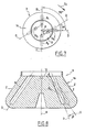
- FIGS. 1 and 2 schematically illustrate a centrifuge 1 which comprises a vessel 2, a rotor 3 disposed in the vessel 2, and means 4 for driving the rotor 3 in rotation about a substantially vertical axis of rotation A.
- the tank 2 comprises a mobile access door 6 and means of refrigerating its interior atmosphere, which refrigeration means are not shown in the figures.
- the rotor 3 is a generally frustoconical rotor of central axis A. It is equipped with a removable closure cover 7. The lid 7 has not been shown on the figure 2 .
- the rotor 3 is for example made of metal and four eccentric housings with respect to the axis A are formed, namely a first pair of housing 8 1 and 8 2 and a second pair of housing 10 1 and 10 2 . It will be noted that the housings 10 1 and 10 2 are not represented on the figure 1 .
- the housings 8 1 and 8 2 of the first pair are symmetrical to each other with respect to the axis A.
- the housings 10 1 and 10 2 of the second pair are symmetrical to each other relative to each other. to axis A.
- the housings 8 1 , 8 2 , 10 1 and 10 2 have an elongated similar shape along a respective longitudinal direction D.
- each direction D is inclined with respect to the axis of rotation A and the section at a geometrical point situated above the rotor 3 and its cover 7.
- the housings 8 1 , 8 2 , 10 1 and 10 2 open into the upper surface 12 of the rotor to allow, when the lid 7 is removed, to introduce into the housing containers containing the product or products to be centrifuged, for example tubes closed by plugs.
- the rotor 3 would be invariant by a geometric rotation of axis A and angle equal to 90 ° ⁇ 2 ⁇ r ⁇ at ⁇ d .
- the geometric image I dashed line of the housing 8 1 by such a rotation in a first direction S 1 would be merged with the housing 10 1 , housing directly following the housing 8 1 in this direction S 1 .
- the housing 10 1 is not confused with this image I but is, in plan view, angularly offset from this image I by a non-zero angle ⁇ centered on the axis A and negative with respect to the direction S 1 .
- the housing 10 1 is the image, by a geometric rotation of axis A and angle ⁇ , of the image I.
- the longitudinal directions D of the housings 10 1 and of the image I form in plan view an angle ⁇ centered on the axis A and negative considering the direction S 1 .
- the angle ⁇ is for example 4 ° and may be more generally between 2 ° and 10 °.
- the housing 10 2 is angularly offset, in top view, of the not shown frame of the housing 8 2 with the aforementioned rotation.
- the housings 8 1 , 8 2 , 10 1 and 10 2 are invariant by a geometric rotation of axis A and angle equal to 180 ° ⁇ rad) but not by a rotation of axis A and angle of 90 ° ⁇ 2 ⁇ r ⁇ at ⁇ d as in the state of the art.
- the reason for this decrease or removal of noise may be as follows.
- the zones Z ( figure 1 ) of the outer lateral surface 14 of the rotor 3 situated radially facing the housings 8 1 , 8 2 , 10 1 and 10 2 are deformed, under the effect of the centrifugal force, radially outwards more strongly than the zones of the outer lateral surface 14 located between the housing.
- the reliefs thus created on the surface 14 are, like the housings 8 1 , 8 2 , 10 1 and 10 2 , invariant by a geometric rotation of axis A and angle equal to 180 ° ( ⁇ rad), and not by a geometric rotation of axis A and angle equal to 90 ° as in the state of the art.
- the frequencies and intensities of the acoustic waves created during the rotational drive of the rotor are modified and the noise is reduced or eliminated.
- the unbalance caused by the irregularity of disposition of the dwellings is relatively weak and acceptable because ⁇ is relatively small.
- the angle ⁇ can be positive with respect to the direction S 1 .
- housings 8 1 , 8 2 , 10 1 and 10 2 are conceivable.
- the housing 10 1 is in top view translated laterally, with respect to the image I of the housing 8 1 , opposite to the direction S 1 of a non-zero distance d .
- the longitudinal directions D of the housing 10 1 and the image I of the housing 8 1 are substantially parallel and spaced laterally from one another.
- the distance d is for example 2mm and may be more generally between 1 and 5mm.
- the housing 10 1 may be, in top view, laterally offset from the image I of the housing 8 1 in the direction S 1 .
- the housing 10 1 may be, in top view, derived from a geometric translation of the image I, the direction of this translation not being necessarily orthogonal to the direction D of the image I.
- the housing 10 1 can be deduced from the image I of the housing 8 1 by a geometric transformation in a radial plane containing the axis of rotation A and the longitudinal direction D of the image I.
- figures 4 and 5 illustrate a third embodiment in which the longitudinal direction D of the housing 10 1 is angularly offset by a non-zero angle ⁇ with respect to the longitudinal direction D of the image I in the abovementioned plane P ( figure 4 ).
- This plane P also contains the direction D of the housing 10 1 and corresponds to the right half-plane of the figure 5 .
- the housing 10 1 is the image, by a geometric rotation of angle ⁇ in the plane P, of the image I.
- angle ⁇ can be positive or negative.
- This angle ⁇ has for example a value of 4 ° and may be more generally between 2 ° and 10 °.
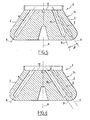
- the figure 6 illustrates another embodiment in which the housing 10 1 is obtained from the image I by geometric translation of a substantially constant distance ⁇ nonzero in the radial plane P.
- the directions D of the housing 10 1 and the I image are substantially parallel and spaced from each other.
- the aforementioned translation may be such that the housing 10 1 is closer to or further from the outer lateral surface 14 than the image I.
- the angle ⁇ or the distance ⁇ are sufficiently small so that, on the one hand, the homogeneity of the centrifugation treatment experienced by products received in the housings 8 1 , 8 2 , 10 1 and 10 2 is satisfactory and on the other hand the unbalances are reduced.
- the figure 7 illustrates yet another embodiment where the housing 10 1 is the image by a geometric transformation of the image I, this geometric transformation comprising a geometric rotation and a geometric translation in the plane of the figure 7 which is orthogonal to the axis of rotation A.
- the rotation is a rotation of axis A and angle ⁇ .
- Translation is a translation in the plane of the figure 7 a non-zero distance d in a direction that is not orthogonal to the direction D of the image I.
- the figure 8 illustrates another embodiment where the housing 10 1 is obtained from the image I by a geometric transformation comprising a geometric rotation and a geometric translation in the radial plane P which comprises the axis of rotation A and the longitudinal direction D of the image I.
- the rotation is a non-zero rotation of angle ⁇ and the translation a translation of a non-zero distance ⁇ in a direction orthogonal to the axis A.
- the combination of a translation and a rotation makes it possible to increase the homogeneity of the centrifugation treatment undergone by products received in the housings 8 1 , 8 2 , 10 1 and 10 2 , to limit unbalance and to reduce aesthetic discomfort.
- the geometric transformation between the image I and the housing 1 may comprise a translation and / or a rotation in a plane orthogonal to the axis of rotation A, and a translation and / or rotation in a radial plane containing axis A.
- translations and rotations described above can be applied, for example separately each to a respective pair of housing when the number of housing is even and strictly greater than 4.
- the housings are symmetrical in pairs with respect to the axis A.
- the rotor 3 when the rotor 3 is provided with an even number n of housings, the rotor 3 will be invariant by a geometric rotation of axis A and of angle 180 ° which limits the unbalance. More generally, an invariance by a geometric rotation of axis A and angle strictly greater than 360 ⁇ ° not will limit the unbalance.
- first housing whose geometric image, by a geometric rotation around the axis of rotation A and angle 360 / n ° in a direction of rotation, is distinct from a second housing of the rotor, this second housing directly following the first housing in the direction of rotation chosen.
Landscapes
- Centrifugal Separators (AREA)
Claims (3)
- Zentrifuge mit einer Schale (2), einem Rotor (3), der in der Schale (2) angeordnet werden soll, und Mitteln (4) zum Rotationsantrieb des Rotors (3) um eine zentrale Rotationsachse (A) bei Geschwindigkeiten über 10.000 U/min, wobei in dem Rotor eine Anzahl n von Aufnahmen (81, 82, 101, 102) zur Aufnahme eines zu zentrifugierenden Produkts vorgesehen sind, wobei die Aufnahmen bezüglich der Rotationsachse exzentrisch sind, dadurch gekennzeichnet, dass das geometrische Bild (I) mindestens einer ersten Aufnahme (81) bezüglich einer geometrischen Rotation um die Rotationsachse (A) in einer ersten Rotationsrichtung (S1) und um einen Winkel von
 - eine geometrische Rotation um einen von Null verschiedenen Winkel (α) in einer zur Rotationsachse (A) senkrechten Ebene, und/oder- eine geometrische Parallelverschiebung um einen von Null verschiedenen Abstand (d) in einer zur Rotationsachse (A) senkrechten Ebene, wobei die Richtung dieser Parallelverschiebung bezüglich der Längsrichtung (D) des geometrischen Bildes (I) der ersten Aufnahme geneigt ist,und dass die geometrische Transformation ferner umfasst:- eine geometrische Rotation um einen von Null verschiedenen Winkel (β) in einer Ebene, die die Rotationsachse (A) und die Längsrichtung des geometrischen Bildes (I) der ersten Aufnahme (81) enthält, und/oder- eine geometrische Parallelverschiebung um einen von Null verschiedenen Abstand (δ) in einer Ebene, die die Rotationsachse (A) und die Längsrichtung (D) des geometrischen Bildes (I) der ersten Aufnahme (81) enthält.
 - Zentrifuge nach Anspruch 1, dadurch gekennzeichnet, dass die Aufnahmen (81, 82, 101, 102) bezüglich einer geometrischen Rotation um die Rotationsachse und um einen Winkel streng oberhalb

- Zentrifuge nach Anspruch 2, dadurch gekennzeichnet, dass n eine gerade Zahl ist, die größer oder gleich 4 ist, und die Aufnahmen (81, 82, 101, 102) bezüglich der Rotationsachse (A) paarweise symmetrisch sind.
Priority Applications (1)
| Application Number | Priority Date | Filing Date | Title |
|---|---|---|---|
| DE60301735.5T DE60301735T3 (de) | 2002-01-09 | 2003-01-07 | Rotor mit Behälteraufnahmen für zu zentrifugierende Produkte und entsprechende Zentrifuge |
Applications Claiming Priority (2)
| Application Number | Priority Date | Filing Date | Title |
|---|---|---|---|
| FR0200219A FR2834479B1 (fr) | 2002-01-09 | 2002-01-09 | Rotor a disposition amelioree de logements de reception de produits a centrifuger et centrifugeuse correspondante |
| FR0200219 | 2002-01-09 |
Publications (3)
| Publication Number | Publication Date |
|---|---|
| EP1329263A1 EP1329263A1 (de) | 2003-07-23 |
| EP1329263B1 EP1329263B1 (de) | 2005-10-05 |
| EP1329263B2 true EP1329263B2 (de) | 2014-07-30 |
Family
ID=8871212
Family Applications (1)
| Application Number | Title | Priority Date | Filing Date |
|---|---|---|---|
| EP03290034.2A Expired - Lifetime EP1329263B2 (de) | 2002-01-09 | 2003-01-07 | Rotor mit Behälteraufnahmen für zu zentrifugierende Produkte und entsprechende Zentrifuge |
Country Status (4)
| Country | Link |
|---|---|
| US (1) | US6986731B2 (de) |
| EP (1) | EP1329263B2 (de) |
| DE (1) | DE60301735T3 (de) |
| FR (1) | FR2834479B1 (de) |
Families Citing this family (2)
| Publication number | Priority date | Publication date | Assignee | Title |
|---|---|---|---|---|
| DE102008032073B4 (de) * | 2008-07-08 | 2015-02-05 | Thermo Electron Led Gmbh | Ausschwingeinheit für eine Zentrifuge |
| CN104056731B (zh) * | 2014-06-10 | 2017-03-29 | 苏州培英实验设备有限公司 | 离心振荡混匀一体机 |
Citations (1)
| Publication number | Priority date | Publication date | Assignee | Title |
|---|---|---|---|---|
| JPH1133436A (ja) † | 1997-07-23 | 1999-02-09 | Hitachi Koki Co Ltd | 遠心分離機用アングルロータ |
Family Cites Families (11)
| Publication number | Priority date | Publication date | Assignee | Title |
|---|---|---|---|---|
| US3339836A (en) * | 1965-02-02 | 1967-09-05 | Internat Equipment Company | Centrifuges |
| DE3341323C2 (de) * | 1983-11-15 | 1987-02-19 | Heraeus Separationstechnik GmbH, 3360 Osterode | Laboratoriumszentrifuge |
| US4553955A (en) * | 1984-06-01 | 1985-11-19 | Beckman Instruments, Inc. | Multi-angle adapter for fixed angle centrifuge rotor |
| US4820257A (en) * | 1988-05-10 | 1989-04-11 | Beckman Instruments, Inc. | Rotor noise suppression |
| JPH05138072A (ja) * | 1991-11-25 | 1993-06-01 | Hitachi Koki Co Ltd | 遠心分離機用ロータ |
| JP3456552B2 (ja) * | 1994-10-05 | 2003-10-14 | 株式会社久保田製作所 | 遠心分離機のアングルロータ |
| US5605529A (en) * | 1996-01-17 | 1997-02-25 | Norfolk Scientific, Inc. | High efficiency centrifuge rotor |
| JP3617172B2 (ja) * | 1996-03-29 | 2005-02-02 | 日立工機株式会社 | 遠心分離機用ロータおよび遠心機 |
| JPH1015436A (ja) * | 1996-07-09 | 1998-01-20 | Tomy Seiko:Kk | 遠心分離方法および遠心分離機 |
| JPH10328582A (ja) * | 1997-05-29 | 1998-12-15 | Tomy Seiko:Kk | 遠心分離機のロータ |
| JP3967849B2 (ja) * | 1998-07-01 | 2007-08-29 | 株式会社トミー精工 | 遠心分離機 |
-
2002
- 2002-01-09 FR FR0200219A patent/FR2834479B1/fr not_active Expired - Fee Related
-
2003
- 2003-01-07 EP EP03290034.2A patent/EP1329263B2/de not_active Expired - Lifetime
- 2003-01-07 DE DE60301735.5T patent/DE60301735T3/de not_active Expired - Lifetime
- 2003-01-09 US US10/338,710 patent/US6986731B2/en not_active Expired - Lifetime
Patent Citations (1)
| Publication number | Priority date | Publication date | Assignee | Title |
|---|---|---|---|---|
| JPH1133436A (ja) † | 1997-07-23 | 1999-02-09 | Hitachi Koki Co Ltd | 遠心分離機用アングルロータ |
Also Published As
| Publication number | Publication date |
|---|---|
| US6986731B2 (en) | 2006-01-17 |
| FR2834479B1 (fr) | 2004-11-19 |
| FR2834479A1 (fr) | 2003-07-11 |
| DE60301735T3 (de) | 2015-02-19 |
| DE60301735D1 (de) | 2005-11-10 |
| EP1329263A1 (de) | 2003-07-23 |
| US20030158026A1 (en) | 2003-08-21 |
| EP1329263B1 (de) | 2005-10-05 |
| DE60301735T2 (de) | 2006-03-16 |
Similar Documents
| Publication | Publication Date | Title |
|---|---|---|
| EP0911080B1 (de) | Zentrifuge mit abnehmbarem Rotor und einer Einrichtung zur axialen Verriegelung des Rotors auf der Antriebswelle, sowie Rotor für eine solche Zentrifuge | |
| JP6406033B2 (ja) | 遠心機及び遠心機用スイングロータ | |
| FR2526105A1 (fr) | Embrayage, notamment pour vehicule automobile, avec un assemblage ameliore du couvercle sur le plateau de reaction | |
| EP2399675A2 (de) | Zentrifugenprobenbehälter und Zentrifuge | |
| EP2313958B1 (de) | Interner rotor für eine elektrische drehmaschine mit t-förmigen magnetischen keilen | |
| EP1329263B2 (de) | Rotor mit Behälteraufnahmen für zu zentrifugierende Produkte und entsprechende Zentrifuge | |
| WO2010020333A2 (fr) | Rotor interieur a arbre rainure pour machine electrique tournante | |
| FR2844877A1 (fr) | Procede pour l'equilibrage rotatif d'un rotor de turbocompresseur avec machine electrique rotative | |
| FR2750924A1 (fr) | Roue acoustiquement amortissante | |
| FR2594191A1 (fr) | Embrayage a friction | |
| US7214177B2 (en) | Culture tube and angle rotor receiving the tube in centrifuge | |
| EP0720701B1 (de) | Kupplungsdeckel und kupplung mit einem solchen deckel | |
| EP0014138B1 (de) | Vorrichtung zum Fixieren der Fahrzeugräder auf einer Auswuchtmaschine | |
| FR3087481A1 (fr) | Ensemble d’equilibrage modulaire pour turbomachine | |
| CH683753A5 (fr) | Centrifugeur comportant un rotor à carénage. | |
| JP5224151B2 (ja) | 遠心分離用ロータ及び遠心機 | |
| JP3326764B2 (ja) | 遠心分離機用アングルロータ | |
| EP1646797B1 (de) | Verfahren zum ausgleich eines kupplungsmechanismus und abdeckung dafür | |
| JP2007152209A (ja) | 遠心分離機用ロータおよび遠心分離機 | |
| US6866622B2 (en) | Centrifugal rotor having buckets swingably supported on a hinge shaft | |
| JP3677840B2 (ja) | 遠心分離機用ロータ | |
| EP3386360A1 (de) | Lebensmittelzubereitungsvorrichtung | |
| JP2605179Y2 (ja) | 遠心分離機用アングルロータとチューブ保持板 | |
| CA3259731A1 (en) | Rotor de machine electrique tournante et ensemble ralentisseur electromagnetique et generatrice | |
| EP3971657B1 (de) | Verfahren zum trennen eines bodens und einer mit diesem gemeinsam ein uhrengehäuse begrenzenden mittelteils, und uhr mit einem boden, der eine aussparung zum aufnehmen eines werkzeugs aufweist |
Legal Events
| Date | Code | Title | Description |
|---|---|---|---|
| PUAI | Public reference made under article 153(3) epc to a published international application that has entered the european phase |
Free format text: ORIGINAL CODE: 0009012 |
|
| 17P | Request for examination filed |
Effective date: 20030524 |
|
| AK | Designated contracting states |
Designated state(s): DE ES FR GB IT TR |
|
| AX | Request for extension of the european patent |
Extension state: AL LT LV MK RO |
|
| AKX | Designation fees paid |
Designated state(s): DE ES FR GB IT TR |
|
| GRAP | Despatch of communication of intention to grant a patent |
Free format text: ORIGINAL CODE: EPIDOSNIGR1 |
|
| GRAS | Grant fee paid |
Free format text: ORIGINAL CODE: EPIDOSNIGR3 |
|
| GRAA | (expected) grant |
Free format text: ORIGINAL CODE: 0009210 |
|
| AK | Designated contracting states |
Kind code of ref document: B1 Designated state(s): DE ES FR GB IT TR |
|
| PG25 | Lapsed in a contracting state [announced via postgrant information from national office to epo] |
Ref country code: IT Free format text: LAPSE BECAUSE OF FAILURE TO SUBMIT A TRANSLATION OF THE DESCRIPTION OR TO PAY THE FEE WITHIN THE PRESCRIBED TIME-LIMIT;WARNING: LAPSES OF ITALIAN PATENTS WITH EFFECTIVE DATE BEFORE 2007 MAY HAVE OCCURRED AT ANY TIME BEFORE 2007. THE CORRECT EFFECTIVE DATE MAY BE DIFFERENT FROM THE ONE RECORDED. Effective date: 20051005 |
|
| REG | Reference to a national code |
Ref country code: GB Ref legal event code: FG4D Free format text: NOT ENGLISH |
|
| REF | Corresponds to: |
Ref document number: 60301735 Country of ref document: DE Date of ref document: 20051110 Kind code of ref document: P |
|
| PG25 | Lapsed in a contracting state [announced via postgrant information from national office to epo] |
Ref country code: ES Free format text: LAPSE BECAUSE OF FAILURE TO SUBMIT A TRANSLATION OF THE DESCRIPTION OR TO PAY THE FEE WITHIN THE PRESCRIBED TIME-LIMIT Effective date: 20060116 |
|
| GBT | Gb: translation of ep patent filed (gb section 77(6)(a)/1977) |
Effective date: 20060116 |
|
| PLBI | Opposition filed |
Free format text: ORIGINAL CODE: 0009260 |
|
| 26 | Opposition filed |
Opponent name: SIGMA LABORZENTRIFUGEN GMBH Effective date: 20060201 |
|
| PLAX | Notice of opposition and request to file observation + time limit sent |
Free format text: ORIGINAL CODE: EPIDOSNOBS2 |
|
| PLBB | Reply of patent proprietor to notice(s) of opposition received |
Free format text: ORIGINAL CODE: EPIDOSNOBS3 |
|
| APBP | Date of receipt of notice of appeal recorded |
Free format text: ORIGINAL CODE: EPIDOSNNOA2O |
|
| APAH | Appeal reference modified |
Free format text: ORIGINAL CODE: EPIDOSCREFNO |
|
| APBQ | Date of receipt of statement of grounds of appeal recorded |
Free format text: ORIGINAL CODE: EPIDOSNNOA3O |
|
| PG25 | Lapsed in a contracting state [announced via postgrant information from national office to epo] |
Ref country code: TR Free format text: LAPSE BECAUSE OF FAILURE TO SUBMIT A TRANSLATION OF THE DESCRIPTION OR TO PAY THE FEE WITHIN THE PRESCRIBED TIME-LIMIT Effective date: 20051005 |
|
| PGFP | Annual fee paid to national office [announced via postgrant information from national office to epo] |
Ref country code: FR Payment date: 20100208 Year of fee payment: 8 |
|
| APBU | Appeal procedure closed |
Free format text: ORIGINAL CODE: EPIDOSNNOA9O |
|
| PGFP | Annual fee paid to national office [announced via postgrant information from national office to epo] |
Ref country code: GB Payment date: 20110105 Year of fee payment: 9 |
|
| REG | Reference to a national code |
Ref country code: FR Ref legal event code: ST Effective date: 20110930 |
|
| PG25 | Lapsed in a contracting state [announced via postgrant information from national office to epo] |
Ref country code: FR Free format text: LAPSE BECAUSE OF NON-PAYMENT OF DUE FEES Effective date: 20110131 |
|
| GBPC | Gb: european patent ceased through non-payment of renewal fee |
Effective date: 20120107 |
|
| PG25 | Lapsed in a contracting state [announced via postgrant information from national office to epo] |
Ref country code: GB Free format text: LAPSE BECAUSE OF NON-PAYMENT OF DUE FEES Effective date: 20120107 |
|
| PLAB | Opposition data, opponent's data or that of the opponent's representative modified |
Free format text: ORIGINAL CODE: 0009299OPPO |
|
| R26 | Opposition filed (corrected) |
Opponent name: SIGMA LABORZENTRIFUGEN GMBH Effective date: 20060201 |
|
| PUAH | Patent maintained in amended form |
Free format text: ORIGINAL CODE: 0009272 |
|
| STAA | Information on the status of an ep patent application or granted ep patent |
Free format text: STATUS: PATENT MAINTAINED AS AMENDED |
|
| 27A | Patent maintained in amended form |
Effective date: 20140730 |
|
| AK | Designated contracting states |
Kind code of ref document: B2 Designated state(s): DE ES FR GB IT TR |
|
| REG | Reference to a national code |
Ref country code: DE Ref legal event code: R102 Ref document number: 60301735 Country of ref document: DE |
|
| REG | Reference to a national code |
Ref country code: DE Ref legal event code: R102 Ref document number: 60301735 Country of ref document: DE Effective date: 20140730 |
|
| REG | Reference to a national code |
Ref country code: DE Ref legal event code: R135 Ref document number: 60301735 Country of ref document: DE |
|
| REG | Reference to a national code |
Ref country code: DE Ref legal event code: R073 Ref document number: 60301735 Country of ref document: DE |
|
| REG | Reference to a national code |
Ref country code: DE Ref legal event code: R074 Ref document number: 60301735 Country of ref document: DE |
|
| REG | Reference to a national code |
Ref country code: DE Ref legal event code: R135 Ref document number: 60301735 Country of ref document: DE Effective date: 20141031 |
|
| REG | Reference to a national code |
Ref country code: DE Ref legal event code: R074 Ref document number: 60301735 Country of ref document: DE Effective date: 20141218 |
|
| PGFP | Annual fee paid to national office [announced via postgrant information from national office to epo] |
Ref country code: DE Payment date: 20181228 Year of fee payment: 17 |
|
| REG | Reference to a national code |
Ref country code: DE Ref legal event code: R119 Ref document number: 60301735 Country of ref document: DE |
|
| PG25 | Lapsed in a contracting state [announced via postgrant information from national office to epo] |
Ref country code: DE Free format text: LAPSE BECAUSE OF NON-PAYMENT OF DUE FEES Effective date: 20200801 |