EP1329263B2 - Rotor with cavities for receiving a product for centrifuging and corresponding centrifuge - Google Patents
Rotor with cavities for receiving a product for centrifuging and corresponding centrifuge Download PDFInfo
- Publication number
- EP1329263B2 EP1329263B2 EP03290034.2A EP03290034A EP1329263B2 EP 1329263 B2 EP1329263 B2 EP 1329263B2 EP 03290034 A EP03290034 A EP 03290034A EP 1329263 B2 EP1329263 B2 EP 1329263B2
- Authority
- EP
- European Patent Office
- Prior art keywords
- rotation
- axis
- geometrical
- rotor
- image
- Prior art date
- Legal status (The legal status is an assumption and is not a legal conclusion. Google has not performed a legal analysis and makes no representation as to the accuracy of the status listed.)
- Expired - Lifetime
Links
Images


Classifications
-
- B—PERFORMING OPERATIONS; TRANSPORTING
- B04—CENTRIFUGAL APPARATUS OR MACHINES FOR CARRYING-OUT PHYSICAL OR CHEMICAL PROCESSES
- B04B—CENTRIFUGES
- B04B5/00—Other centrifuges
- B04B5/04—Radial chamber apparatus for separating predominantly liquid mixtures, e.g. butyrometers
- B04B5/0407—Radial chamber apparatus for separating predominantly liquid mixtures, e.g. butyrometers for liquids contained in receptacles
- B04B5/0414—Radial chamber apparatus for separating predominantly liquid mixtures, e.g. butyrometers for liquids contained in receptacles comprising test tubes
Definitions
- the present invention relates to a centrifuge according to the preamble of claim 1. Such centrifuges are known from the state of the art.
- the invention applies, for example, to the centrifugation of biological products.
- rotors For the centrifugation of such products, generally frustoconical shaped rotors in which the housings have been formed in the form of recesses. These housings have elongated shapes and are, for each rotor, regularly distributed around its axis of rotation. These housings are intended to receive, for example, tubes containing the products to be centrifuged and closed by plugs.
- the document JP-A-09262503 , US 6,045,494 and JP-A-0926 2503 describe rotors with a particular housing arrangement.
- a centrifuge using such a rotor generally comprises a vessel, provided with refrigeration means and wherein the rotor is mounted on a rotating drive head.
- An object of the invention is to solve this problem by limiting the noise caused by the rotational drive of rotors of the aforementioned type.
- the subject of the invention is a centrifuge according to claim 1.
- the centrifuge may comprise one or more of the features of the dependent claims.
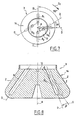
- FIGS. 1 and 2 schematically illustrate a centrifuge 1 which comprises a vessel 2, a rotor 3 disposed in the vessel 2, and means 4 for driving the rotor 3 in rotation about a substantially vertical axis of rotation A.
- the tank 2 comprises a mobile access door 6 and means of refrigerating its interior atmosphere, which refrigeration means are not shown in the figures.
- the rotor 3 is a generally frustoconical rotor of central axis A. It is equipped with a removable closure cover 7. The lid 7 has not been shown on the figure 2 .
- the rotor 3 is for example made of metal and four eccentric housings with respect to the axis A are formed, namely a first pair of housing 8 1 and 8 2 and a second pair of housing 10 1 and 10 2 . It will be noted that the housings 10 1 and 10 2 are not represented on the figure 1 .
- the housings 8 1 and 8 2 of the first pair are symmetrical to each other with respect to the axis A.
- the housings 10 1 and 10 2 of the second pair are symmetrical to each other relative to each other. to axis A.
- the housings 8 1 , 8 2 , 10 1 and 10 2 have an elongated similar shape along a respective longitudinal direction D.
- each direction D is inclined with respect to the axis of rotation A and the section at a geometrical point situated above the rotor 3 and its cover 7.
- the housings 8 1 , 8 2 , 10 1 and 10 2 open into the upper surface 12 of the rotor to allow, when the lid 7 is removed, to introduce into the housing containers containing the product or products to be centrifuged, for example tubes closed by plugs.
- the rotor 3 would be invariant by a geometric rotation of axis A and angle equal to 90 ° ⁇ 2 ⁇ r ⁇ at ⁇ d .
- the geometric image I dashed line of the housing 8 1 by such a rotation in a first direction S 1 would be merged with the housing 10 1 , housing directly following the housing 8 1 in this direction S 1 .
- the housing 10 1 is not confused with this image I but is, in plan view, angularly offset from this image I by a non-zero angle ⁇ centered on the axis A and negative with respect to the direction S 1 .
- the housing 10 1 is the image, by a geometric rotation of axis A and angle ⁇ , of the image I.
- the longitudinal directions D of the housings 10 1 and of the image I form in plan view an angle ⁇ centered on the axis A and negative considering the direction S 1 .
- the angle ⁇ is for example 4 ° and may be more generally between 2 ° and 10 °.
- the housing 10 2 is angularly offset, in top view, of the not shown frame of the housing 8 2 with the aforementioned rotation.
- the housings 8 1 , 8 2 , 10 1 and 10 2 are invariant by a geometric rotation of axis A and angle equal to 180 ° ⁇ rad) but not by a rotation of axis A and angle of 90 ° ⁇ 2 ⁇ r ⁇ at ⁇ d as in the state of the art.
- the reason for this decrease or removal of noise may be as follows.
- the zones Z ( figure 1 ) of the outer lateral surface 14 of the rotor 3 situated radially facing the housings 8 1 , 8 2 , 10 1 and 10 2 are deformed, under the effect of the centrifugal force, radially outwards more strongly than the zones of the outer lateral surface 14 located between the housing.
- the reliefs thus created on the surface 14 are, like the housings 8 1 , 8 2 , 10 1 and 10 2 , invariant by a geometric rotation of axis A and angle equal to 180 ° ( ⁇ rad), and not by a geometric rotation of axis A and angle equal to 90 ° as in the state of the art.
- the frequencies and intensities of the acoustic waves created during the rotational drive of the rotor are modified and the noise is reduced or eliminated.
- the unbalance caused by the irregularity of disposition of the dwellings is relatively weak and acceptable because ⁇ is relatively small.
- the angle ⁇ can be positive with respect to the direction S 1 .
- housings 8 1 , 8 2 , 10 1 and 10 2 are conceivable.
- the housing 10 1 is in top view translated laterally, with respect to the image I of the housing 8 1 , opposite to the direction S 1 of a non-zero distance d .
- the longitudinal directions D of the housing 10 1 and the image I of the housing 8 1 are substantially parallel and spaced laterally from one another.
- the distance d is for example 2mm and may be more generally between 1 and 5mm.
- the housing 10 1 may be, in top view, laterally offset from the image I of the housing 8 1 in the direction S 1 .
- the housing 10 1 may be, in top view, derived from a geometric translation of the image I, the direction of this translation not being necessarily orthogonal to the direction D of the image I.
- the housing 10 1 can be deduced from the image I of the housing 8 1 by a geometric transformation in a radial plane containing the axis of rotation A and the longitudinal direction D of the image I.
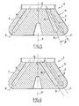
- figures 4 and 5 illustrate a third embodiment in which the longitudinal direction D of the housing 10 1 is angularly offset by a non-zero angle ⁇ with respect to the longitudinal direction D of the image I in the abovementioned plane P ( figure 4 ).
- This plane P also contains the direction D of the housing 10 1 and corresponds to the right half-plane of the figure 5 .
- the housing 10 1 is the image, by a geometric rotation of angle ⁇ in the plane P, of the image I.
- angle ⁇ can be positive or negative.
- This angle ⁇ has for example a value of 4 ° and may be more generally between 2 ° and 10 °.
- the figure 6 illustrates another embodiment in which the housing 10 1 is obtained from the image I by geometric translation of a substantially constant distance ⁇ nonzero in the radial plane P.
- the directions D of the housing 10 1 and the I image are substantially parallel and spaced from each other.
- the aforementioned translation may be such that the housing 10 1 is closer to or further from the outer lateral surface 14 than the image I.
- the angle ⁇ or the distance ⁇ are sufficiently small so that, on the one hand, the homogeneity of the centrifugation treatment experienced by products received in the housings 8 1 , 8 2 , 10 1 and 10 2 is satisfactory and on the other hand the unbalances are reduced.
- the figure 7 illustrates yet another embodiment where the housing 10 1 is the image by a geometric transformation of the image I, this geometric transformation comprising a geometric rotation and a geometric translation in the plane of the figure 7 which is orthogonal to the axis of rotation A.
- the rotation is a rotation of axis A and angle ⁇ .
- Translation is a translation in the plane of the figure 7 a non-zero distance d in a direction that is not orthogonal to the direction D of the image I.
- the figure 8 illustrates another embodiment where the housing 10 1 is obtained from the image I by a geometric transformation comprising a geometric rotation and a geometric translation in the radial plane P which comprises the axis of rotation A and the longitudinal direction D of the image I.
- the rotation is a non-zero rotation of angle ⁇ and the translation a translation of a non-zero distance ⁇ in a direction orthogonal to the axis A.
- the combination of a translation and a rotation makes it possible to increase the homogeneity of the centrifugation treatment undergone by products received in the housings 8 1 , 8 2 , 10 1 and 10 2 , to limit unbalance and to reduce aesthetic discomfort.
- the geometric transformation between the image I and the housing 1 may comprise a translation and / or a rotation in a plane orthogonal to the axis of rotation A, and a translation and / or rotation in a radial plane containing axis A.
- translations and rotations described above can be applied, for example separately each to a respective pair of housing when the number of housing is even and strictly greater than 4.
- the housings are symmetrical in pairs with respect to the axis A.
- the rotor 3 when the rotor 3 is provided with an even number n of housings, the rotor 3 will be invariant by a geometric rotation of axis A and of angle 180 ° which limits the unbalance. More generally, an invariance by a geometric rotation of axis A and angle strictly greater than 360 ⁇ ° not will limit the unbalance.
- first housing whose geometric image, by a geometric rotation around the axis of rotation A and angle 360 / n ° in a direction of rotation, is distinct from a second housing of the rotor, this second housing directly following the first housing in the direction of rotation chosen.
Description
La présente invention concerne une centrifugeuse selon le préambule de la revendication 1. De telles centrifugeuses sont connues de l'état de la technique.The present invention relates to a centrifuge according to the preamble of
L'invention s'applique, par exemple, à la centrifugation de produits biologiques.The invention applies, for example, to the centrifugation of biological products.
Pour la centrifugation de tels produits, on utilise généralement des rotors de formes tronconiques dans lesquels les logements ont été ménagés sous forme d'évidements. Ces logements ont des formes allongées et sont, pour chaque rotor, régulièrement répartis autour de son axe de rotation. Ces logements sont destinés à recevoir, par exemple, des tubes contenant les produits à centrifuger et fermés par des bouchons. Le document
Une centrifugeuse utilisant un tel rotor comprend généralement une cuve, munie de moyens de réfrigération et dans laquelle le rotor est monté sur une tête d'entraînement en rotation.A centrifuge using such a rotor generally comprises a vessel, provided with refrigeration means and wherein the rotor is mounted on a rotating drive head.
On a constaté dans les ultracentrifugeuses, c'est à dire les centrifugeuses entraînant les rotors à des vitesses de l'ordre de 20000tr/mn, l'apparition de nuisances sonores telles que des sifflements.It has been found in the ultracentrifuges, ie the centrifuges driving the rotors at speeds of the order of 20000rpm, the appearance of noise such as hissing.
Un but de l'invention est de résoudre ce problème en limitant les nuisances sonores provoquées par l'entraînement en rotation de rotors du type précité.An object of the invention is to solve this problem by limiting the noise caused by the rotational drive of rotors of the aforementioned type.
A cet effet, l'invention a pour objet une centrifugeuse selon la revendication 1.For this purpose, the subject of the invention is a centrifuge according to
Selon des modes particuliers de réalisation, la centrifugeuse peut comprendre l'une ou plusieurs des caractéristiques des revendications dépendantes.According to particular embodiments, the centrifuge may comprise one or more of the features of the dependent claims.
L'invention sera mieux comprise à la lecture de la description qui va suivre, donnée uniquement à titre d'exemple, et faite en se référant aux dessins annexés, sur lesquels :
- la
figure 1 est une vue schématique latérale d'une centrifugeuse, - la
figure 2 est une vue schématique du dessus du rotor de lafigure 1 , - les
figures 3 et 4 sont des vues analogues à lafigure 2 illustrant respectivement un deuxième et un troisième modes de réalisation du rotor, - la
figure 5 est une vue schématique, agrandie et en coupe du rotor de lafigure 4 , prise suivant la ligne brisée V-V, - la
figure 6 est une vue analogue à lafigure 5 illustrant un quatrième mode de réalisation du rotor, - la
figure 7 est une vue analogue à lafigure 2 illustrant un cinquième mode de réalisation du rotor, et - la
figure 8 est une vue analogue à lafigure 5 illustrant un sixième mode de réalisation du rotor.
- the
figure 1 is a schematic side view of a centrifuge, - the
figure 2 is a schematic view of the top of the rotor of thefigure 1 , - the
Figures 3 and 4 are similar views to thefigure 2 respectively illustrating second and third embodiments of the rotor, - the
figure 5 is a schematic view, enlarged and in section of the rotor of thefigure 4 , taken along the broken line VV, - the
figure 6 is a view similar to thefigure 5 illustrating a fourth embodiment of the rotor, - the
figure 7 is a view similar to thefigure 2 illustrating a fifth embodiment of the rotor, and - the
figure 8 is a view similar to thefigure 5 illustrating a sixth embodiment of the rotor.
Les
De manière classique, la cuve 2 comprend une porte mobile d'accès 6 et des moyens de réfrigération de son atmosphère intérieure, lesquels moyens de réfrigération ne sont pas représentés sur les figures.In a conventional manner, the
Le rotor 3 est un rotor de forme générale tronconique d'axe central A. Il est équipé d'un couvercle de fermeture 7 amovible. Le couvercle 7 n'a pas été représenté sur la
Le rotor 3 est par exemple réalisé en métal et quatre logements excentrés par rapport à l'axe A y sont ménagés, à savoir une première paire de logements 81 et 82 et une seconde paire de logements 101 et 102. On notera que les logements 101 et 102 ne sont pas représentés sur la
Les logements 81 et 82 de la première paire sont symétriques l'un de l'autre par rapport à l'axe A. Les logements 101 et 102 de la seconde paire sont symétriques l'un de l'autre par rapport à l'axe A.The housings 8 1 and 8 2 of the first pair are symmetrical to each other with respect to the axis A. The housings 10 1 and 10 2 of the second pair are symmetrical to each other relative to each other. to axis A.
Les logements 81, 82, 101 et 102 ont une forme analogue allongée le long d'une direction longitudinale respective D.The housings 8 1 , 8 2 , 10 1 and 10 2 have an elongated similar shape along a respective longitudinal direction D.
Comme on le voit sur la
Les logements 81, 82, 101 et 102 débouchent dans la surface supérieure 12 du rotor pour permettre, lorsque le couvercle 7 est retiré, d'introduire dans les logements des récipients contenant le ou les produits à centrifuger, par exemple des tubes fermés par des bouchons.The housings 8 1 , 8 2 , 10 1 and 10 2 open into the
Sur la
Comme on le voit sur la
Si une telle répartition était régulière, le rotor 3 serait invariant par une rotation géométrique d'axe A et d'angle valant 90° ![]()
![]()
Dans le rotor des
En d'autres termes, le logement 101 est l'image, par une rotation géométrique d'axe A et d'angle α, de l'image I.In other words, the housing 10 1 is the image, by a geometric rotation of axis A and angle α, of the image I.
Ainsi, les directions longitudinales D des logements 101 et de l'image I forment en vue de dessus un angle α centré sur l'axe A et négatif en considérant le sens S1.Thus, the longitudinal directions D of the housings 10 1 and of the image I form in plan view an angle α centered on the axis A and negative considering the direction S 1 .
L'angle α vaut par exemple 4° et peut être compris plus généralement entre 2° et 10°.The angle α is for example 4 ° and may be more generally between 2 ° and 10 °.
On notera que sur la
De même, le logement 102 est décalé angulairement, en vue de dessus, de l'image non représentée du logement 82 par la rotation précitée.Similarly, the housing 10 2 is angularly offset, in top view, of the not shown frame of the housing 8 2 with the aforementioned rotation.
Ainsi, les logement 81, 82, 101 et 102 sont invariants par une rotation géométrique d'axe A et d'angle valant 180° π rad) mais pas par une rotation d'axe A et d'angle valant 90° ![]()
![]()
On a constaté, lorsque l'on entraîne en rotation le rotor 3 à des vitesses relativement importantes, typiquement supérieures à 10000tr/min, que les nuisances sonores telles que les sifflements sont fortement diminuées, voire supprimées.It has been found, when rotating the
On estime à l'heure actuelle que la raison de cette diminution ou suppression des nuisances sonores peut être la suivante. Lorsque le rotor 3 est entraîné en rotation, les zones Z (
Par ailleurs, les balourds engendrés par l'irrégularité de disposition des logements sont relativement faibles et acceptables grâce au fait que α est relativement faible.In addition, the unbalance caused by the irregularity of disposition of the dwellings is relatively weak and acceptable because α is relatively small.
Selon une variante du mode de réalisation des
De manière plus générale, d'autres dispositions des logements 81, 82, 101 et 102 sont envisageables.More generally, other arrangements of the housings 8 1 , 8 2 , 10 1 and 10 2 are conceivable.
Ainsi, dans le mode de réalisation de la
La distance d vaut par exemple 2mm et peut être plus généralement comprise entre 1 et 5mm.The distance d is for example 2mm and may be more generally between 1 and 5mm.
On notera que sur la
Cette distance étant relativement faible, la différence entre les forces de centrifugation auxquelles les produits reçus dans les logements 81, 82, 101 et 102 seront soumis restera suffisamment faible et acceptable pour l'homogénéité du traitement de centrifugation. De même, les balourds provoqués par l'irrégularité de disposition restent acceptables.As this distance is relatively small, the difference between the centrifugal forces at which the products received in the housings 8 1 , 8 2 , 10 1 and 10 2 will be subjected will remain sufficiently small and acceptable for the homogeneity of the centrifugation treatment. Similarly, the unbalance caused by the irregularity of disposition remain acceptable.
Selon une variante non représentée, le logement 101 peut être, en vue de dessus, décalé latéralement de l'image I du logement 81 dans le sens S1.According to a variant not shown, the housing 10 1 may be, in top view, laterally offset from the image I of the housing 8 1 in the direction S 1 .
De manière plus générale, le logement 101 peut être, en vue de dessus, issu d'une translation géométrique de l'image I, la direction de cette translation n'étant pas nécessairement orthogonale à la direction D de l'image I.More generally, the housing 10 1 may be, in top view, derived from a geometric translation of the image I, the direction of this translation not being necessarily orthogonal to the direction D of the image I.
De manière plus générale encore, le logement 101 peut être déduit de l'image I du logement 81 par une transformation géométrique dans un plan radial contenant l'axe de rotation A et la direction longitudinale D de l'image I.More generally, the housing 10 1 can be deduced from the image I of the housing 8 1 by a geometric transformation in a radial plane containing the axis of rotation A and the longitudinal direction D of the image I.
Ainsi, les
On notera que l'angle β peut être positif ou négatif. Cet angle β a par exemple une valeur de 4° et peut être plus généralement compris entre 2° et 10°.It will be noted that the angle β can be positive or negative. This angle β has for example a value of 4 ° and may be more generally between 2 ° and 10 °.
La
On notera que sur les
On notera également que l'angle β ou la distance δ sont suffisamment faibles pour que d'une part l'homogénéité du traitement de centrifugation subi par des produits reçus dans les logements 81, 82, 101 et 102 soit satisfaisante et d'autre part les balourds soient réduits.It will also be noted that the angle β or the distance δ are sufficiently small so that, on the one hand, the homogeneity of the centrifugation treatment experienced by products received in the housings 8 1 , 8 2 , 10 1 and 10 2 is satisfactory and on the other hand the unbalances are reduced.
De manière plus générale les principes ci-dessus peuvent être appliqués à des rotors comprenant un nombre quelconque de logements.More generally, the above principles can be applied to rotors comprising any number of housings.
Ils peuvent également être combinés entre eux pour un même logement.They can also be combined with each other for the same dwelling.
Ainsi, la
Plus précisément, la rotation est une rotation d'axe A et d'angle α.More precisely, the rotation is a rotation of axis A and angle α.
La translation est une translation dans le plan de la
La combinaison d'une rotation et d'une translation au sein de la transformation géométrique permet au logement 101 de rester suffisamment proche de l'image I pour limiter les différences entre la force de centrifugation subie par un produit contenu dans le logement 101 et la force de centrifugation d'un produit reçu dans le logement 81.Combining a rotation and a translation in the geometric transformation allows the housing 10 1 remain sufficiently close to the I picture to limit the differences between the centrifugal force experienced by a product contained in the housing 10 1 and the centrifugation force of a product received in the housing 8 1 .
Ainsi, l'homogénéité du traitement de centrifugation subi par des produits reçus dans les logements 81, 82, 101 et 102 est accrue. En outre, cette combinaison permet de réduire les balourds ainsi que la différence d'aspect entre un rotor incorporant les principes de l'invention et un rotor classique.Thus, the homogeneity of the centrifugation treatment undergone by products received in the housings 8 1 , 8 2 , 10 1 and 10 2 is increased. In addition, this combination reduces unbalance and the difference in appearance between a rotor incorporating the principles of the invention and a conventional rotor.
De manière analogue, la
Plus précisément, la rotation est une rotation d'angle β non nul et la translation une translation d'une distance δ non nulle dans une direction orthogonale à l'axe A.More precisely, the rotation is a non-zero rotation of angle β and the translation a translation of a non-zero distance δ in a direction orthogonal to the axis A.
Ici encore, la combinaison d'une translation et d'une rotation permet d'augmenter l'homogénéité du traitement de centrifugation subi par des produits reçus dans les logements 81, 82, 101 et 102, de limiter les balourds et de réduire les désagréments esthétiques.Here again, the combination of a translation and a rotation makes it possible to increase the homogeneity of the centrifugation treatment undergone by products received in the housings 8 1 , 8 2 , 10 1 and 10 2 , to limit unbalance and to reduce aesthetic discomfort.
Plus généralement, la transformation géométrique entre l'image I et le logement 101 peut comprendre une translation et/ou une rotation dans un plan orthogonal à l'axe de rotation A, et une translation et/ou une rotation dans un plan radial contenant l'axe A.More generally, the geometric transformation between the image I and the housing 1 may comprise a translation and / or a rotation in a plane orthogonal to the axis of rotation A, and a translation and / or rotation in a radial plane containing axis A.
De manière générale également, les translations et rotations décrites précédemment peuvent être appliquées, par exemple séparément chacune à une paire respective de logements lorsque le nombre de logements est pair et strictement supérieur à 4.Also generally, translations and rotations described above can be applied, for example separately each to a respective pair of housing when the number of housing is even and strictly greater than 4.
De préférence, les logements sont symétriques par paires par rapport à l'axe A. Ainsi, lorsque le rotor 3 est muni d'un nombre n pair de logements, le rotor 3 sera invariant par une rotation géométrique d'axe A et d'angle 180° ce qui permet de limiter les balourds. De manière plus générale, une invariance par une rotation géométrique d'axe A et d'angle strictement supérieur à ![]()
![]()
Pour éviter l'apparition de nuisances sonores, il existera toujours au moins un premier logement dont l'image géométrique, par une rotation géométrique autour de l'axe de rotation A et d'angle 360/n° dans un sens de rotation, est distincte d'un deuxième logement du rotor, ce deuxième logement suivant directement le premier logement dans le sens de rotation choisi.To avoid the appearance of noise, there will always be at least one first housing whose geometric image, by a geometric rotation around the axis of rotation A and angle 360 / n ° in a direction of rotation, is distinct from a second housing of the rotor, this second housing directly following the first housing in the direction of rotation chosen.
Claims (3)
- A centrifuge comprising a tank (2), a rotor (3) intended to be disposed in the tank (2) and means (4) for imparting rotating motion to the rotor (3) about a central axis of rotation (A) at speeds above 10,000 rpm, a number n of compartments (81, 82, 101, 102) being provided inside the rotor for receiving a product to be centrifuged, the compartments being offset in relation to the axis of rotation, characterized in that the geometrical image (I) of at least one first compartment (81), by geometrical rotation about the axis of rotation (A) in a first direction of rotation (S1) and by an angle
 - a geometrical rotation by an angle (α) which is not zero in a plane perpendicular to the axis of rotation (A), and/or- a geometrical translation by a distance (d) which is not zero in a plane perpendicular to the axis of rotation (A), the direction of this translation being inclined in relation to the longitudinal direction (D) of the geometrical image (I) of the first compartment,and that the geometrical transformation further comprises:- a geometrical rotation by an angle (β) which is not zero in a plane containing the axis of rotation (A) and the longitudinal direction of the geometrical image (I) of the first compartment (81), and/or- a geometrical translation by a distance (δ) which is not zero in a plane containing the axis of rotation (A) and the longitudinal direction (D) of the geometrical image (I) of the first compartment (81).
 - A centrifuge according to claim 1, characterized in that the compartments (81, 82, 101, 102) are invariant by a geometrical rotation about the axis of rotation and by an angle strictly greater than

- A centrifuge according to claim 2, characterized in that n is an even number higher than or equal to 4 and the compartments (81, 82, 101, 102) are symmetrical in pairs in relation to the axis of rotation (A).
Priority Applications (1)
| Application Number | Priority Date | Filing Date | Title |
|---|---|---|---|
| DE60301735.5T DE60301735T3 (en) | 2002-01-09 | 2003-01-07 | Rotor with container receptacles for products to be centrifuged and corresponding centrifuge |
Applications Claiming Priority (2)
| Application Number | Priority Date | Filing Date | Title |
|---|---|---|---|
| FR0200219A FR2834479B1 (en) | 2002-01-09 | 2002-01-09 | ROTOR HAVING IMPROVED PROVISION OF RECEIVING HOUSES FOR CENTRIFUGAL PRODUCTS AND CORRESPONDING CENTRIFUGES |
| FR0200219 | 2002-01-09 |
Publications (3)
| Publication Number | Publication Date |
|---|---|
| EP1329263A1 EP1329263A1 (en) | 2003-07-23 |
| EP1329263B1 EP1329263B1 (en) | 2005-10-05 |
| EP1329263B2 true EP1329263B2 (en) | 2014-07-30 |
Family
ID=8871212
Family Applications (1)
| Application Number | Title | Priority Date | Filing Date |
|---|---|---|---|
| EP03290034.2A Expired - Lifetime EP1329263B2 (en) | 2002-01-09 | 2003-01-07 | Rotor with cavities for receiving a product for centrifuging and corresponding centrifuge |
Country Status (4)
| Country | Link |
|---|---|
| US (1) | US6986731B2 (en) |
| EP (1) | EP1329263B2 (en) |
| DE (1) | DE60301735T3 (en) |
| FR (1) | FR2834479B1 (en) |
Families Citing this family (2)
| Publication number | Priority date | Publication date | Assignee | Title |
|---|---|---|---|---|
| DE102008032073B4 (en) * | 2008-07-08 | 2015-02-05 | Thermo Electron Led Gmbh | Swing-out unit for a centrifuge |
| CN104056731B (en) * | 2014-06-10 | 2017-03-29 | 苏州培英实验设备有限公司 | Centrifugation vibration mixes all-in-one |
Citations (1)
| Publication number | Priority date | Publication date | Assignee | Title |
|---|---|---|---|---|
| JPH1133436A (en) † | 1997-07-23 | 1999-02-09 | Hitachi Koki Co Ltd | Angle rotor for centrifugal separator |
Family Cites Families (11)
| Publication number | Priority date | Publication date | Assignee | Title |
|---|---|---|---|---|
| US3339836A (en) * | 1965-02-02 | 1967-09-05 | Internat Equipment Company | Centrifuges |
| DE3341323A1 (en) * | 1983-11-15 | 1985-05-30 | Heraeus-Christ Gmbh, 3360 Osterode | Laboratory centrifuge |
| US4553955A (en) * | 1984-06-01 | 1985-11-19 | Beckman Instruments, Inc. | Multi-angle adapter for fixed angle centrifuge rotor |
| US4820257A (en) * | 1988-05-10 | 1989-04-11 | Beckman Instruments, Inc. | Rotor noise suppression |
| JPH05138072A (en) * | 1991-11-25 | 1993-06-01 | Hitachi Koki Co Ltd | Rotor for centrifuge |
| JP3456552B2 (en) * | 1994-10-05 | 2003-10-14 | 株式会社久保田製作所 | Angle rotor of centrifuge |
| US5605529A (en) * | 1996-01-17 | 1997-02-25 | Norfolk Scientific, Inc. | High efficiency centrifuge rotor |
| JP3617172B2 (en) * | 1996-03-29 | 2005-02-02 | 日立工機株式会社 | Centrifuge rotor and centrifuge |
| JPH1015436A (en) * | 1996-07-09 | 1998-01-20 | Tomy Seiko:Kk | Centrifugal separation method and centrifugal separator |
| JPH10328582A (en) * | 1997-05-29 | 1998-12-15 | Tomy Seiko:Kk | Rotor of centrifuge |
| JP3967849B2 (en) * | 1998-07-01 | 2007-08-29 | 株式会社トミー精工 | centrifuge |
-
2002
- 2002-01-09 FR FR0200219A patent/FR2834479B1/en not_active Expired - Fee Related
-
2003
- 2003-01-07 EP EP03290034.2A patent/EP1329263B2/en not_active Expired - Lifetime
- 2003-01-07 DE DE60301735.5T patent/DE60301735T3/en not_active Expired - Lifetime
- 2003-01-09 US US10/338,710 patent/US6986731B2/en not_active Expired - Lifetime
Patent Citations (1)
| Publication number | Priority date | Publication date | Assignee | Title |
|---|---|---|---|---|
| JPH1133436A (en) † | 1997-07-23 | 1999-02-09 | Hitachi Koki Co Ltd | Angle rotor for centrifugal separator |
Also Published As
| Publication number | Publication date |
|---|---|
| EP1329263A1 (en) | 2003-07-23 |
| EP1329263B1 (en) | 2005-10-05 |
| DE60301735T3 (en) | 2015-02-19 |
| FR2834479B1 (en) | 2004-11-19 |
| FR2834479A1 (en) | 2003-07-11 |
| DE60301735T2 (en) | 2006-03-16 |
| DE60301735D1 (en) | 2005-11-10 |
| US6986731B2 (en) | 2006-01-17 |
| US20030158026A1 (en) | 2003-08-21 |
Similar Documents
| Publication | Publication Date | Title |
|---|---|---|
| EP0911080B1 (en) | Centrifuge with dismountable rotor and a device for the axial locking of the rotor on the drive shaft and rotor for such a centrifuge | |
| JP6406033B2 (en) | Centrifuge and swing rotor for centrifuge | |
| FR2828162A1 (en) | METHOD FOR MOUNTING A CLUTCH SYSTEM | |
| FR2526105A1 (en) | CLUTCH, PARTICULARLY FOR MOTOR VEHICLES, WITH IMPROVED ASSEMBLY OF THE COVER ON THE REACTION TRAY | |
| EP3005910B1 (en) | Press with screw pressing | |
| EP1329263B2 (en) | Rotor with cavities for receiving a product for centrifuging and corresponding centrifuge | |
| EP2316156A2 (en) | Internal rotor including a grooved shaft, intended for a rotary electric machine | |
| FR2844877A1 (en) | Turbocompressor rotor balancing method in which both primary and secondary resonance effects are balanced simultaneously | |
| EP2850982B1 (en) | Device for driving a rotary tool for food processing apparatus, and food processing apparatus provided with such a drive device | |
| FR3087481A1 (en) | MODULAR BALANCING ASSEMBLY FOR TURBOMACHINE | |
| JP4329207B2 (en) | Centrifuge rotor and centrifuge | |
| EP3184379A1 (en) | Cap and driving arm for a wiping device for a motor vehicle | |
| FR2558527A1 (en) | AUTOMATIC DECOMPRESSION SYSTEM FOR STARTING AN ENGINE | |
| US7214177B2 (en) | Culture tube and angle rotor receiving the tube in centrifuge | |
| FR2839396A1 (en) | Electric motor with improved support for shaft, uses a packing ring made of an elastic material between bearing and bearing housing to avoid vibration and compensate misalignment | |
| JP5224151B2 (en) | Centrifuge rotor and centrifuge | |
| JP2004049970A (en) | Centrifuge and adapter for centrifuge | |
| FR3017432A1 (en) | ASSEMBLY METHOD FOR BALANCING A CLUTCH, AND CLUTCH | |
| JP3326764B2 (en) | Angle rotor for centrifuge | |
| FR2635123A1 (en) | SUPPORT DISC FOR WHEEL ROTOR SUPPORT DISC TERMINALS WITH OPEN END (OE) | |
| EP1182138A1 (en) | Device for assembling products like compact disc cases | |
| US6866622B2 (en) | Centrifugal rotor having buckets swingably supported on a hinge shaft | |
| EP1646797B1 (en) | Method for balancing a clutch mechanism and a cover therefor | |
| JP2567557Y2 (en) | Protective cover for sample container for centrifuge | |
| EP2160584B1 (en) | Transmission shaft attachment tooling and balancing stand comprising such tooling |
Legal Events
| Date | Code | Title | Description |
|---|---|---|---|
| PUAI | Public reference made under article 153(3) epc to a published international application that has entered the european phase |
Free format text: ORIGINAL CODE: 0009012 |
|
| 17P | Request for examination filed |
Effective date: 20030524 |
|
| AK | Designated contracting states |
Designated state(s): DE ES FR GB IT TR |
|
| AX | Request for extension of the european patent |
Extension state: AL LT LV MK RO |
|
| AKX | Designation fees paid |
Designated state(s): DE ES FR GB IT TR |
|
| GRAP | Despatch of communication of intention to grant a patent |
Free format text: ORIGINAL CODE: EPIDOSNIGR1 |
|
| GRAS | Grant fee paid |
Free format text: ORIGINAL CODE: EPIDOSNIGR3 |
|
| GRAA | (expected) grant |
Free format text: ORIGINAL CODE: 0009210 |
|
| AK | Designated contracting states |
Kind code of ref document: B1 Designated state(s): DE ES FR GB IT TR |
|
| PG25 | Lapsed in a contracting state [announced via postgrant information from national office to epo] |
Ref country code: IT Free format text: LAPSE BECAUSE OF FAILURE TO SUBMIT A TRANSLATION OF THE DESCRIPTION OR TO PAY THE FEE WITHIN THE PRESCRIBED TIME-LIMIT;WARNING: LAPSES OF ITALIAN PATENTS WITH EFFECTIVE DATE BEFORE 2007 MAY HAVE OCCURRED AT ANY TIME BEFORE 2007. THE CORRECT EFFECTIVE DATE MAY BE DIFFERENT FROM THE ONE RECORDED. Effective date: 20051005 |
|
| REG | Reference to a national code |
Ref country code: GB Ref legal event code: FG4D Free format text: NOT ENGLISH |
|
| REF | Corresponds to: |
Ref document number: 60301735 Country of ref document: DE Date of ref document: 20051110 Kind code of ref document: P |
|
| PG25 | Lapsed in a contracting state [announced via postgrant information from national office to epo] |
Ref country code: ES Free format text: LAPSE BECAUSE OF FAILURE TO SUBMIT A TRANSLATION OF THE DESCRIPTION OR TO PAY THE FEE WITHIN THE PRESCRIBED TIME-LIMIT Effective date: 20060116 |
|
| GBT | Gb: translation of ep patent filed (gb section 77(6)(a)/1977) |
Effective date: 20060116 |
|
| PLBI | Opposition filed |
Free format text: ORIGINAL CODE: 0009260 |
|
| 26 | Opposition filed |
Opponent name: SIGMA LABORZENTRIFUGEN GMBH Effective date: 20060201 |
|
| PLAX | Notice of opposition and request to file observation + time limit sent |
Free format text: ORIGINAL CODE: EPIDOSNOBS2 |
|
| PLBB | Reply of patent proprietor to notice(s) of opposition received |
Free format text: ORIGINAL CODE: EPIDOSNOBS3 |
|
| APBP | Date of receipt of notice of appeal recorded |
Free format text: ORIGINAL CODE: EPIDOSNNOA2O |
|
| APAH | Appeal reference modified |
Free format text: ORIGINAL CODE: EPIDOSCREFNO |
|
| APBQ | Date of receipt of statement of grounds of appeal recorded |
Free format text: ORIGINAL CODE: EPIDOSNNOA3O |
|
| PG25 | Lapsed in a contracting state [announced via postgrant information from national office to epo] |
Ref country code: TR Free format text: LAPSE BECAUSE OF FAILURE TO SUBMIT A TRANSLATION OF THE DESCRIPTION OR TO PAY THE FEE WITHIN THE PRESCRIBED TIME-LIMIT Effective date: 20051005 |
|
| PGFP | Annual fee paid to national office [announced via postgrant information from national office to epo] |
Ref country code: FR Payment date: 20100208 Year of fee payment: 8 |
|
| APBU | Appeal procedure closed |
Free format text: ORIGINAL CODE: EPIDOSNNOA9O |
|
| PGFP | Annual fee paid to national office [announced via postgrant information from national office to epo] |
Ref country code: GB Payment date: 20110105 Year of fee payment: 9 |
|
| REG | Reference to a national code |
Ref country code: FR Ref legal event code: ST Effective date: 20110930 |
|
| PG25 | Lapsed in a contracting state [announced via postgrant information from national office to epo] |
Ref country code: FR Free format text: LAPSE BECAUSE OF NON-PAYMENT OF DUE FEES Effective date: 20110131 |
|
| GBPC | Gb: european patent ceased through non-payment of renewal fee |
Effective date: 20120107 |
|
| PG25 | Lapsed in a contracting state [announced via postgrant information from national office to epo] |
Ref country code: GB Free format text: LAPSE BECAUSE OF NON-PAYMENT OF DUE FEES Effective date: 20120107 |
|
| PLAB | Opposition data, opponent's data or that of the opponent's representative modified |
Free format text: ORIGINAL CODE: 0009299OPPO |
|
| R26 | Opposition filed (corrected) |
Opponent name: SIGMA LABORZENTRIFUGEN GMBH Effective date: 20060201 |
|
| PUAH | Patent maintained in amended form |
Free format text: ORIGINAL CODE: 0009272 |
|
| STAA | Information on the status of an ep patent application or granted ep patent |
Free format text: STATUS: PATENT MAINTAINED AS AMENDED |
|
| 27A | Patent maintained in amended form |
Effective date: 20140730 |
|
| AK | Designated contracting states |
Kind code of ref document: B2 Designated state(s): DE ES FR GB IT TR |
|
| REG | Reference to a national code |
Ref country code: DE Ref legal event code: R102 Ref document number: 60301735 Country of ref document: DE |
|
| REG | Reference to a national code |
Ref country code: DE Ref legal event code: R102 Ref document number: 60301735 Country of ref document: DE Effective date: 20140730 |
|
| REG | Reference to a national code |
Ref country code: DE Ref legal event code: R135 Ref document number: 60301735 Country of ref document: DE |
|
| REG | Reference to a national code |
Ref country code: DE Ref legal event code: R073 Ref document number: 60301735 Country of ref document: DE |
|
| REG | Reference to a national code |
Ref country code: DE Ref legal event code: R074 Ref document number: 60301735 Country of ref document: DE |
|
| REG | Reference to a national code |
Ref country code: DE Ref legal event code: R135 Ref document number: 60301735 Country of ref document: DE Effective date: 20141031 |
|
| REG | Reference to a national code |
Ref country code: DE Ref legal event code: R074 Ref document number: 60301735 Country of ref document: DE Effective date: 20141218 |
|
| PGFP | Annual fee paid to national office [announced via postgrant information from national office to epo] |
Ref country code: DE Payment date: 20181228 Year of fee payment: 17 |
|
| REG | Reference to a national code |
Ref country code: DE Ref legal event code: R119 Ref document number: 60301735 Country of ref document: DE |
|
| PG25 | Lapsed in a contracting state [announced via postgrant information from national office to epo] |
Ref country code: DE Free format text: LAPSE BECAUSE OF NON-PAYMENT OF DUE FEES Effective date: 20200801 |