EP2850982B1 - Device for driving a rotary tool for food processing apparatus, and food processing apparatus provided with such a drive device - Google Patents
Device for driving a rotary tool for food processing apparatus, and food processing apparatus provided with such a drive device Download PDFInfo
- Publication number
- EP2850982B1 EP2850982B1 EP14185427.3A EP14185427A EP2850982B1 EP 2850982 B1 EP2850982 B1 EP 2850982B1 EP 14185427 A EP14185427 A EP 14185427A EP 2850982 B1 EP2850982 B1 EP 2850982B1
- Authority
- EP
- European Patent Office
- Prior art keywords
- driving
- hub
- driven
- central axis
- branches
- Prior art date
- Legal status (The legal status is an assumption and is not a legal conclusion. Google has not performed a legal analysis and makes no representation as to the accuracy of the status listed.)
- Active
Links
- 235000013305 food Nutrition 0.000 title claims description 24
- 230000000694 effects Effects 0.000 claims description 9
- 230000002093 peripheral effect Effects 0.000 claims description 8
- 235000012055 fruits and vegetables Nutrition 0.000 claims description 4
- 210000001331 nose Anatomy 0.000 description 8
- 230000000295 complement effect Effects 0.000 description 4
- 210000003128 head Anatomy 0.000 description 4
- 230000005540 biological transmission Effects 0.000 description 2
- 238000004140 cleaning Methods 0.000 description 2
- 235000013311 vegetables Nutrition 0.000 description 2
- 241000251468 Actinopterygii Species 0.000 description 1
- 241000207199 Citrus Species 0.000 description 1
- 241001415961 Gaviidae Species 0.000 description 1
- 235000020971 citrus fruits Nutrition 0.000 description 1
- 230000007423 decrease Effects 0.000 description 1
- 235000013399 edible fruits Nutrition 0.000 description 1
- 210000000887 face Anatomy 0.000 description 1
- 235000019688 fish Nutrition 0.000 description 1
- 235000011389 fruit/vegetable juice Nutrition 0.000 description 1
- 230000005484 gravity Effects 0.000 description 1
- 230000001939 inductive effect Effects 0.000 description 1
- 235000013372 meat Nutrition 0.000 description 1
- 238000009987 spinning Methods 0.000 description 1
Images


Classifications
-
- F—MECHANICAL ENGINEERING; LIGHTING; HEATING; WEAPONS; BLASTING
- F16—ENGINEERING ELEMENTS AND UNITS; GENERAL MEASURES FOR PRODUCING AND MAINTAINING EFFECTIVE FUNCTIONING OF MACHINES OR INSTALLATIONS; THERMAL INSULATION IN GENERAL
- F16D—COUPLINGS FOR TRANSMITTING ROTATION; CLUTCHES; BRAKES
- F16D1/00—Couplings for rigidly connecting two coaxial shafts or other movable machine elements
- F16D1/10—Quick-acting couplings in which the parts are connected by simply bringing them together axially
- F16D1/108—Quick-acting couplings in which the parts are connected by simply bringing them together axially having retaining means rotating with the coupling and acting by interengaging parts, i.e. positive coupling
-
- A—HUMAN NECESSITIES
- A47—FURNITURE; DOMESTIC ARTICLES OR APPLIANCES; COFFEE MILLS; SPICE MILLS; SUCTION CLEANERS IN GENERAL
- A47J—KITCHEN EQUIPMENT; COFFEE MILLS; SPICE MILLS; APPARATUS FOR MAKING BEVERAGES
- A47J43/00—Implements for preparing or holding food, not provided for in other groups of this subclass
- A47J43/04—Machines for domestic use not covered elsewhere, e.g. for grinding, mixing, stirring, kneading, emulsifying, whipping or beating foodstuffs, e.g. power-driven
- A47J43/046—Machines for domestic use not covered elsewhere, e.g. for grinding, mixing, stirring, kneading, emulsifying, whipping or beating foodstuffs, e.g. power-driven with tools driven from the bottom side
-
- A—HUMAN NECESSITIES
- A47—FURNITURE; DOMESTIC ARTICLES OR APPLIANCES; COFFEE MILLS; SPICE MILLS; SUCTION CLEANERS IN GENERAL
- A47J—KITCHEN EQUIPMENT; COFFEE MILLS; SPICE MILLS; APPARATUS FOR MAKING BEVERAGES
- A47J43/00—Implements for preparing or holding food, not provided for in other groups of this subclass
- A47J43/04—Machines for domestic use not covered elsewhere, e.g. for grinding, mixing, stirring, kneading, emulsifying, whipping or beating foodstuffs, e.g. power-driven
- A47J43/07—Parts or details, e.g. mixing tools, whipping tools
- A47J43/08—Driving mechanisms
- A47J43/085—Driving mechanisms for machines with tools driven from the lower side
-
- F—MECHANICAL ENGINEERING; LIGHTING; HEATING; WEAPONS; BLASTING
- F16—ENGINEERING ELEMENTS AND UNITS; GENERAL MEASURES FOR PRODUCING AND MAINTAINING EFFECTIVE FUNCTIONING OF MACHINES OR INSTALLATIONS; THERMAL INSULATION IN GENERAL
- F16D—COUPLINGS FOR TRANSMITTING ROTATION; CLUTCHES; BRAKES
- F16D43/00—Automatic clutches
- F16D43/02—Automatic clutches actuated entirely mechanically
- F16D43/04—Automatic clutches actuated entirely mechanically controlled by angular speed
- F16D43/14—Automatic clutches actuated entirely mechanically controlled by angular speed with centrifugal masses actuating the clutching members directly in a direction which has at least a radial component; with centrifugal masses themselves being the clutching members
- F16D43/16—Automatic clutches actuated entirely mechanically controlled by angular speed with centrifugal masses actuating the clutching members directly in a direction which has at least a radial component; with centrifugal masses themselves being the clutching members with clutching members having interengaging parts
-
- F—MECHANICAL ENGINEERING; LIGHTING; HEATING; WEAPONS; BLASTING
- F16—ENGINEERING ELEMENTS AND UNITS; GENERAL MEASURES FOR PRODUCING AND MAINTAINING EFFECTIVE FUNCTIONING OF MACHINES OR INSTALLATIONS; THERMAL INSULATION IN GENERAL
- F16D—COUPLINGS FOR TRANSMITTING ROTATION; CLUTCHES; BRAKES
- F16D43/00—Automatic clutches
- F16D43/02—Automatic clutches actuated entirely mechanically
- F16D43/04—Automatic clutches actuated entirely mechanically controlled by angular speed
- F16D43/14—Automatic clutches actuated entirely mechanically controlled by angular speed with centrifugal masses actuating the clutching members directly in a direction which has at least a radial component; with centrifugal masses themselves being the clutching members
- F16D2043/145—Automatic clutches actuated entirely mechanically controlled by angular speed with centrifugal masses actuating the clutching members directly in a direction which has at least a radial component; with centrifugal masses themselves being the clutching members the centrifugal masses being pivoting
Definitions
- the present invention relates to a device for rotating a rotary tool for a food processing apparatus.
- the invention also relates to a food processing apparatus comprising such a training device.
- such an apparatus ensures a treatment of the foods that are admitted to it, in particular by pressing, cutting, grating and / or slicing.
- Such a device finds application to any type of food, whether fruit or vegetables, fish or meat.
- This treatment device is likely to be used in the professions of the hotel industry or catering.
- it may be a juicer for fruit and vegetables, a citrus juicer, a grater disk, or a disc vegetable cutter.
- such a food processing apparatus comprises a tool, which is, in use, rotated by a head integral with a rotary motor shaft on itself, for the purpose of processing food admitted into the apparatus , and which is removable relative to this drive head, in particular for cleaning the tool.
- a centrifuge it conventionally comprises a fixed base, on which is removably attached, a rotary basket, this basket comprising a bottom forming a rasp and side walls extending from this bottom, which is a sieve retaining the pulp formed by grating while allowing the juice to flow.
- An example of such a centrifuge is provided by FR-A-2,829,679 .
- An example of an apparatus, as defined by the preamble of appended claim 1, is provided by WO-2011/001729 .
- the object of the present invention is to provide a food processing apparatus of the type described above, the locking of the removable tool on the rotating drive head is particularly effective, especially to meet the requirements of reliability , durability, stability and silence, relating to professional equipment.
- the subject of the invention is a device for rotating a rotary tool for a food processing apparatus, as defined in claim 1.
- One of the ideas underlying the invention is to seek to lock with each other of the central parts, ie hubs respectively belonging to the rotary tool of the food processing apparatus and to the head of the rotational drive of this tool, acting externally around the driven hub, to allow to transmit a large torque and stably around the central axis defined by the motor shaft of the device.
- the locking of the driving and driven hubs is achieved by flyweights, that is to say mechanical parts using the force centrifugal to create a work, which are arranged externally around the hubs.
- the invention provides that, under the effect of the centrifugal force resulting from the rotation of the drive head by the drive shaft, several flyweights are moved so that a part of each of them approaching the central axis to interfere, typically in support, with the outer face of the hub driven so as to lock the driven and driving hubs with each other, while, in the absence of this force centrifugal, that is to say when the motor shaft is stopped, the flyweights occupy a position that leaves the free hub to be clear of the driving hub in order to easily disconnect the tool vis-à-vis the head of training, especially for cleaning the tool.
- the drive device according to the invention is thus particularly effective, even when the tool is subjected to high transverse stresses to the axis, resulting from its shape, for example in a basket, and / or the presence poorly distributed food around the axis, as explained in more detail later.
- the invention also relates to a food processing apparatus as defined in claim 11. Additional advantageous features of this apparatus are specified in claims 12 and 13.
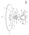
- FIG. 1 to 5 there is shown a device 1 for rotating a tool 2 around a geometric axis XX.
- the device 1 and the tool 2 belong to a food processing apparatus, which is not shown in full in the figures and which, as an example, is one of the devices listed in the introductory part of this document.
- the tool 2 includes a main body 4, which is substantially centered on the axis XX and which, in the figures, has a generally discoidal shape, it being understood that this geometry is not limiting of the present invention with regard to the multitude of embodiments for the tool 2 according to the food processing apparatus to which this tool belongs.
- the main body 4 constitutes the bottom wall of a basket belonging to a centrifuge for fruits and vegetables, the face 4A of this bottom wall, which is turned away from the device of 1, being provided with grating points, not shown in the figures, and a peripheral screen, also not shown.
- the tool 2 can take various forms, such as a basket, a drum, a cylinder, a disk, etc., in order to ensure the various functions resulting from its rotation. on itself about the axis XX, such as functions of grating, cutting, spinning, pressing, slicing, etc., in the field of food processing.
- the following description is oriented relative to the axis XX, considering that the terms “top” and “upper” correspond to an axial direction towards which is turned the face 4A of the main body 4 of the tool 2, the aforementioned axial direction being thus turned towards the upper part of the Figures 1 to 5 , while the terms “lower” and “lower” correspond to an axial direction of opposite direction.
- the face 4A of the main body 4 constitutes the upper face of this body, while its axially opposite face 4B constitutes its lower face.
- the tool 2 includes a hub 6, which is centered on the axis XX and which extends axially downwards from the face 4B of the main body 4 of the tool 2.
- the hub 6 is integral with the main body 4, for example, by being material with him.
- the hub 6 has a tubular overall shape, which is centered on the axis XX and whose cylindrical internal bore 8 is open downwards, as well as open upwards. opening into a central through bore 10 of the main body 4.
- the hub 6 includes an upper ring 12, which is centered on the axis XX, which connects the rest of the hub 6 to the face 4B of the main body 4. It will be noted that the aforementioned ring 12 can, by way of variant not shown, have a larger axial dimension than that illustrated in the figures.
- the outer face of the ring 12 is provided with a hollow recess 14.
- This recess 14 runs over the entire outer periphery of the ring 12 and is delimited, downwards, by a frustoconical surface 14A, centered on the axis XX and diverging downwards.
- the hub 6 further includes three elongated legs 16, which extend in length parallel to the axis XX, projecting downwardly from the ring 12.
- These branches 16 constitute, so to speak, extensions to the bottom of the ring 12, in the sense that the outer and inner faces of each of these branches 16 respectively belong to cylindrical geometric envelopes respectively defined by the inner and outer faces of the ring 12, more generally defined by the faces outer and inner tubular hub 6.
- the legs 16 are arranged regularly about the axis XX, being separated two by two by a slot 20. Each of the slots 20 is open, both downward and in the two directions of a direction radial to the axis XX.
- each of the crenellations 20 is closed at the same time upwards by a peripheral portion of the lower end of the ring 12 and, in a direction peripheral to the axis XX, by two of the branches 16 , succeeding each other around the XX axis.
- each of the branches 16 has a lower axial end 18, which is free and which is tapering downwards, delimiting two edges 18A, opposing each other in a direction peripheral to the axis XX, which converge towards each other downwards.
- each of the opposite edges 18A of the free end 18 is connected, upward, to the lower end of the ring 12 by a straight edge 16A, which is delimited by the corresponding branch 16 and which extends substantially parallel to the axis XX.
- the drive device 1 comprises a shaft 22, which is centered on the axis XX and which is qualified motor in the sense that the shaft 22 is designed to be rotated on itself about the axis XX by a motor, not shown, including an electric motor.
- a motor not shown, including an electric motor.
- the drive device 1 further comprises a hub 24, which is integral with the drive shaft 22.
- the hub 24 has, in the exemplary embodiment considered in the figures, a tubular overall shape, which is centered on the axis XX and whose inner bore 26 coaxially and substantially complementary receives the drive shaft 22.
- the hub 24 and the hub 6 are designed to be engaged with each other to transmit a rotary movement about the axis XX, the tree motor 22 to the main body 4, via, successively, the hub 24 and the hub 6.
- the hub 24 can be qualified as the driving hub while the hub 6 can be called driven hub.
- the hub 24 includes three elongated legs 28, which extend in length parallel to the axis XX and which project upwardly from a lower ring 30 of the hub 24.
- the legs 28 are arranged in a regular manner around the axis XX, being separated two by two by a slot 32.
- the three-branch structure with three slots of the hub 24 is similar to the three-branched structure with three slots of the hub 6: when the tool 2 is assembled to the training device 1, as on the Figures 3 to 5 each of the branches 16 of the hub 6 is received in one of the slots 32 of the hub 24 while each of the legs 28 of the hub 24 is received in one of the slots 20 of the hub 6, thereby engaging one with the other the hubs 6 and 24.
- each of the slots 32 of the hub 24 is hollowed down so that the bottom of the crenel 32 forms walls 32A, arranged facing one another in a direction peripheral to the axis XX, which converge towards each other downwards and which receive between them the tapered free end 18 of the corresponding branch 16 of the hub 6.
- Each of these walls 32A is connected, upwards, to the free end 34 of one of the branches 28 by a straight edge 28A which is delimited by the corresponding branch 28, extending parallel to the axis XX .
- the free end 34 of each branch 28 does not have the same conformation as the free ends 18 of the branches 16 of the hub 6.
- this free end 34 is simply blunted.
- the drive device 1 also comprises weights 36 which, in the embodiment considered here, are carried by a common support 38 integral with the drive shaft 22.
- this support 38 has, here, a tubular overall shape, which is centered on the axis XX and which externally surrounds the hub 24, which arranges the weights externally around the hub 24, and the hub 6 in the presence of the tool 2.
- the support 38 includes a transverse wall 40, a central bore of which is mounted coaxially and complementary around the drive shaft 22 and which is axially interposed between the lower ring 30 of the hub 24 and a shoulder 22A of the motor shaft 22, this transverse wall 40 can thus advantageously participate in the bonding between the hub 24 and the motor shaft 22.
- this transverse wall 40 can be envisaged as regards the arrangement of the drive shaft 22, the hub 24 and the support 38, provided that these three components are, in use, integral with each other, and by any suitable means, not shown in the figures.
- the driving hub 24, the weights 36 and the support 38 belong to a head 42 of driving the tool 2 in rotation around the axis XX, which is integral with the motor shaft 22 and on which the tool 2 is provided to be removably attached.
- the flyweights 36 are three in number, being distributed regularly around the axis X-X, which is to say that they are arranged at 120 ° from each other around this axis.
- Each of the flyweights 36 is mounted to tilt free, relative to the support 38, about an axis Z-Z which is orthoradial to the axis X-X.
- the body 44 of each weight 36 delimits a through-hole 44A, which is centered on the axis ZZ and which receives, in a coaxial and complementary manner, a pin 46, around which the flyweight 36 is freely tilting and which is secured to the support 38.
- each weight 36 includes, projecting from its side facing the axis XX, an upper nose 48 and a lower foot 50, this nose 48 and the foot 50 being located on either side of a geometric plane, containing the axis ZZ and perpendicular to the axis XX.
- the weights 36 each occupy a rest position, which is shown on the figure 3 and wherein, under the gravitational effect of the weight of their body 44, their foot 50 is radially supported, in the direction of the axis XX, against the lower ring 30 of the hub 24, while their nose 48 is radially distant the axis XX of a value strictly greater than the radius of the outer cylindrical face of the hub 6.
- each of the weights 36 tilts around the axis ZZ, under the effect of a centrifugal force resulting from the rotation of the shaft, from its rest position of the figure 3 to a position of use, which is shown on the figure 4 and wherein the foot 50 is further radially away from the axis XX than in the rest position of the weight, while the nose 48 is close to the axis XX, that is to say, it occupies a position radially closer to the axis XX than that occupied in the rest position of the weight.
- this mounting operation of the tool 2 on the drive head 42 is particularly simple, insofar as it is not hampered by the weights 36, in particular by the noses 48 of these weights since these are in their rest position of the figure 3 . In other words, in this configuration, the weights 36 do not interfere with the driven hub 6.
- each of the flyweights 36 axially holds the driven hub 6 in engagement with the driving hub 24, in the sense that, on the one hand , if necessary, the tool 2 is found fully mounted on the drive head 42 and, secondly, any inadvertent release of the tool 2 upwards vis-à-vis the drive device 1 is prevented. And, under the effect of the radial component FR of this bearing force F, the flyweights 36, taken together, ensure the centering of the hub 6 on the axis XX, radially aligning the hub 6 with this axis XX.
- the weights 36 lock, at least axially and, advantageously, coaxially, the drive head 42 with the hub 6 and therefore with the tool 2.
- This lock is particularly effective because it results from an action of the nose 48 of the flyweights 36 on the outer face of the driven hub 6, this action inducing both high efficiency and high stability for driving the tool 2 42.
- the rotary tool 2 is capable of processing a large quantity of food simultaneously, which may be poorly distributed around the axis XX, which induce considerable centrifugal forces, in particular when the tool includes a peripheral basket or the like, and / or which can even induce upward stresses according to the interacti you enter the tool and the food, for example when slicing food.
- the axial component FA of the bearing force F of the flyweights 36 in use position on the hub 6 acts on the branches 16 of the hub 6 so that the opposite edges 18A of each of their free end 18 rest on the walls 32A formed in the bottom of each of the crenellations 32 of the hub 24, forming support components between these edges 18A and these walls 32A, which are, at the same time, parallel to each other.
- XX axis and directed downwards, as indicated by the reference F'A on the figure 5 and orthoradial to this axis XX, as indicated by the reference F'O on the figure 5 .
Description
La présente invention concerne un dispositif d'entrainement en rotation d'un outil rotatif pour un appareil de traitement alimentaire. L'invention concerne également un appareil de traitement alimentaire comportant un tel dispositif d'entrainement.The present invention relates to a device for rotating a rotary tool for a food processing apparatus. The invention also relates to a food processing apparatus comprising such a training device.
Au sens de l'invention, un tel appareil assure un traitement des aliments qui y sont admis, notamment par pressage, découpage, râpage et/ou tranchage. Un tel appareil trouve son application à tout type d'aliment, que ce soit des fruits ou légumes, des poissons ou encore de la viande.Within the meaning of the invention, such an apparatus ensures a treatment of the foods that are admitted to it, in particular by pressing, cutting, grating and / or slicing. Such a device finds application to any type of food, whether fruit or vegetables, fish or meat.
Cet appareil de traitement est susceptible d'utilisation dans les professions de l'hôtellerie ou encore de la restauration. A titre d'exemple non limitatif, il peut s'agir d'une centrifugeuse pour fruits et légumes, d'une ogive presse-agrume, d'un disque de râpe, ou encore d'un disque de coupe-légumes.This treatment device is likely to be used in the professions of the hotel industry or catering. By way of non-limiting example, it may be a juicer for fruit and vegetables, a citrus juicer, a grater disk, or a disc vegetable cutter.
Dans tous les cas, un tel appareil de traitement alimentaire comporte un outil, qui est, en service, entrainé en rotation par une tête solidaire d'un arbre moteur rotatif sur lui-même, aux fins du traitement des aliments admis dans l'appareil, et qui est amovible par rapport à cette tête d'entrainement, notamment aux fins du nettoyage de l'outil. Ainsi, dans le cas d'une centrifugeuse, celle-ci comporte classiquement un socle fixe, sur lequel est rapporté, de façon amovible, un panier rotatif, ce panier comprenant un fond formant râpe ainsi que des parois latérales s'étendant à partir de ce fond, qui constitue un tamis retenant la pulpe formée par râpage tout en laissant s'écouler le jus. Un exemple d'une telle centrifugeuse est fourni par
Le but de la présente invention est de proposer un appareil de traitement alimentaire du type décrit ci-dessus, dont le verrouillage de l'outil amovible sur la tête d'entrainement en rotation est particulièrement performant, notamment en vue de satisfaire les exigences de fiabilité, de durabilité, de stabilité et de silence, relatives aux équipements professionnels.The object of the present invention is to provide a food processing apparatus of the type described above, the locking of the removable tool on the rotating drive head is particularly effective, especially to meet the requirements of reliability , durability, stability and silence, relating to professional equipment.
A cet effet, l'invention a pour objet un dispositif d'entrainement en rotation d'un outil rotatif pour un appareil de traitement alimentaire, tel que défini à la revendication 1.For this purpose, the subject of the invention is a device for rotating a rotary tool for a food processing apparatus, as defined in claim 1.
Une des idées à la base de l'invention est de chercher à verrouiller l'une avec l'autre des parties centrales, autrement dit des moyeux, appartenant respectivement à l'outil rotatif de l'appareil de traitement alimentaire et à la tête d'entrainement en rotation de cet outil, en agissant extérieurement autour du moyeu mené, afin de permettre de transmettre un couple important et de façon stable autour de l'axe central défini par l'arbre moteur de l'appareil. Selon l'invention, le verrouillage des moyeux menant et mené est réalisé par des masselottes, c'est-à-dire des pièces mécaniques utilisant la force centrifuge pour créer un travail, qui sont agencées extérieurement autour des moyeux. Plus précisément, l'invention prévoit que, sous l'effet de la force centrifuge résultant de la mise en rotation de la tête d'entrainement par l'arbre moteur, plusieurs masselottes sont déplacées de façon qu'une partie de chacune d'elles se rapproche de l'axe central jusqu'à interférer, typiquement en appui, avec la face extérieure du moyeu mené de manière à verrouiller l'un avec l'autre les moyeux mené et menant, tandis que, en l'absence de cette force centrifuge, autrement dit lorsque l'arbre moteur est à l'arrêt, les masselottes occupent une position qui laisse le moyeu mené libre d'être dégagé du moyeu menant afin de désaccoupler facilement l'outil vis-à-vis de la tête d'entrainement, en particulier aux fins de nettoyage de l'outil. Le dispositif d'entrainement conforme à l'invention s'avère ainsi particulièrement efficace, même lorsque l'outil est soumis à de fortes contraintes transversales à l'axe, résultant de sa forme, par exemple en panier, et/ou de la présence d'aliments mal répartis autour de l'axe, comme expliqué plus en détail par la suite.One of the ideas underlying the invention is to seek to lock with each other of the central parts, ie hubs respectively belonging to the rotary tool of the food processing apparatus and to the head of the rotational drive of this tool, acting externally around the driven hub, to allow to transmit a large torque and stably around the central axis defined by the motor shaft of the device. According to the invention, the locking of the driving and driven hubs is achieved by flyweights, that is to say mechanical parts using the force centrifugal to create a work, which are arranged externally around the hubs. More specifically, the invention provides that, under the effect of the centrifugal force resulting from the rotation of the drive head by the drive shaft, several flyweights are moved so that a part of each of them approaching the central axis to interfere, typically in support, with the outer face of the hub driven so as to lock the driven and driving hubs with each other, while, in the absence of this force centrifugal, that is to say when the motor shaft is stopped, the flyweights occupy a position that leaves the free hub to be clear of the driving hub in order to easily disconnect the tool vis-à-vis the head of training, especially for cleaning the tool. The drive device according to the invention is thus particularly effective, even when the tool is subjected to high transverse stresses to the axis, resulting from its shape, for example in a basket, and / or the presence poorly distributed food around the axis, as explained in more detail later.
Des caractéristiques additionnelles avantageuses du dispositif d'entrainement conforme à l'invention sont spécifiées aux revendications 2 à 10.Additional advantageous features of the driving device according to the invention are specified in
L'invention a également pour objet un appareil de traitement alimentaire, tel que défini à la revendication 11. Des caractéristiques additionnelles avantageuses de cet appareil sont spécifiées aux revendications 12 et 13.The invention also relates to a food processing apparatus as defined in claim 11. Additional advantageous features of this apparatus are specified in
L'invention sera mieux comprise à la lecture de la description qui va suivre, donnée uniquement à titre d'exemple et faite en se référant aux dessins sur lesquels :
- la
figure 1 est une vue en perspective d'un éclaté d'un dispositif d'entrainement conforme à l'invention, associé à un outil rotatif à entrainer par ce dispositif ; - la
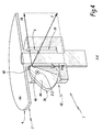
figure 2 est une vue similaire à lafigure 1 , montrant, sous un angle de vue différent, une partie seulement du dispositif d'entrainement, ainsi que l'outil ; - la
figure 3 est une vue en perspective d'une coupe longitudinale du dispositif d'entrainement et de l'outil de lafigure 1 , dans une configuration assemblée et non verrouillée ; - la
figure 4 est une vue similaire à lafigure 3 , illustrant le dispositif d'entrainement et l'outil dans une configuration assemblée et verrouillée ; et - la
figure 5 est une vue similaire à lafigure 2 , montrant la partie précitée du dispositif d'entrainement et l'outil dans la configuration assemblée et verrouillée de lafigure 4 .
- the
figure 1 is a perspective view of an exploded of a drive device according to the invention, associated with a rotary tool to be driven by this device; - the
figure 2 is a view similar to thefigure 1 showing, from a different angle of view, only a part of the driving device, as well as the tool; - the
figure 3 is a perspective view of a longitudinal section of the training device and the tool of thefigure 1 in an assembled and unlocked configuration; - the
figure 4 is a view similar to thefigure 3 illustrating the driving device and the tool in an assembled and locked configuration; and - the
figure 5 is a view similar to thefigure 2 , showing the aforementioned part of the driving device and the tool in the assembled and locked configuration of thefigure 4 .
Sur les
L'outil 2 inclut un corps principal 4, qui est sensiblement centré sur l'axe X-X et qui, sur les figures, présente une forme globalement discoïdale, étant entendu que cette géométrie n'est pas limitative de la présente invention eu égard à la multitude de formes de réalisation pour l'outil 2 selon l'appareil de traitement alimentaire auquel cet outil appartient.The
A titre d'exemple purement illustratif, le corps principal 4 constitue la paroi de fond d'un panier appartenant à une centrifugeuse pour fruits et légumes, la face 4A de cette paroi de fond, qui est tournée à l'opposé du dispositif d'entrainement 1, étant pourvue de pointes de râpage, non représentées sur les figures, ainsi que d'un tamis périphérique, également non représenté.By way of purely illustrative example, the
Plus généralement, on rappelle que l'outil 2 peut prendre des formes diverses, telles qu'un panier, un tambour, un cylindre, un disque, etc., en vue d'assurer des fonctions tout aussi diverses résultant de sa mise en rotation sur lui-même autour de l'axe X-X, telles que des fonctions de râpage, de coupage, d'essorage, de pressage, de tranchage, etc., dans le domaine du traitement d'aliments.More generally, it will be recalled that the
Par commodité, la suite de la description est orientée par rapport à l'axe X-X, en considérant que les termes « haut » et « supérieur » correspondent à une direction axiale vers laquelle est tournée la face 4A du corps principal 4 de l'outil 2, la direction axiale précitée étant donc tournée vers la partie haute des
L'outil 2 inclut un moyeu 6, qui est centré sur l'axe X-X et qui s'étend axialement vers le bas depuis la face 4B du corps principal 4 de l'outil 2. Le moyeu 6 est solidaire du corps principal 4, en étant par exemple venu de matière avec lui. Dans l'exemple de réalisation considéré sur les figures, le moyeu 6 présente une forme globale tubulaire, qui est centrée sur l'axe X-X et dont l'alésage interne cylindrique 8 est ouvert vers le bas, ainsi qu'ouvert vers le haut en débouchant dans un alésage traversant central 10 du corps principal 4.The
Pour des raisons qui apparaîtront plus loin, le moyeu 6 inclut un anneau supérieur 12, qui est centré sur l'axe X-X, qui relie le reste du moyeu 6 à la face 4B du corps principal 4. On notera que l'anneau précité 12 peut, à titre de variante non représentée, présenter une dimension axiale plus importante que celle illustrée sur les figures.For reasons that will appear later, the
La face extérieure de l'anneau 12 est pourvue d'un renfoncement en creux 14. Ce renfoncement 14 court sur toute la périphérie extérieure de l'anneau 12 et est délimité, vers le bas, par une surface tronconique 14A, centrée sur l'axe X-X et divergente vers le bas.The outer face of the
Le moyeu 6 inclut en outre trois branches allongées 16, qui s'étendent en longueur de manière parallèle à l'axe X-X, en faisant saillie vers le bas depuis l'anneau 12. Ces branches 16 constituent, en quelque sorte, des prolongements vers le bas de l'anneau 12, dans le sens où les faces extérieure et intérieure de chacune de ces branches 16 appartiennent respectivement à des enveloppes géométriques cylindriques respectivement définies par les faces intérieure et extérieure de l'anneau 12, plus généralement définies par les faces extérieure et intérieure du moyeu tubulaire 6. Les branches 16 sont disposées de manière régulière autour de l'axe X-X, en étant séparées deux à deux par un créneau 20. Chacun des créneaux 20 est ouvert, à la fois, vers le bas et dans les deux sens d'une direction radiale à l'axe X-X. Dans le même temps, chacun des créneaux 20 est fermé, à la fois, vers le haut par une portion périphérique de l'extrémité inférieure de l'anneau 12 et, suivant une direction périphérique à l'axe X-X, par deux des branches 16, se succédant autour de l'axe X-X.The
Comme bien visible sur la
Comme bien visible sur les
Le dispositif d'entrainement 1 comporte en outre un moyeu 24, qui est solidaire de l'arbre moteur 22. Comme bien visible sur les
Dans l'exemple de réalisation considéré sur les figures, et comme bien visible sur les
Pour des raisons qui apparaîtront plus loin, et à la différence du fond des créneaux 20 du moyeu 6, le fond de chacun des créneaux 32 du moyeu 24 est creusé vers le bas de façon que ce fond du créneau 32 forme des parois 32A, agencées en regard l'une de l'autre suivant une direction périphérique à l'axe X-X, qui sont convergentes l'une vers l'autre vers le bas et qui reçoivent entre elles l'extrémité libre effilée 18 de la branche correspondante 16 du moyeu 6. Chacune de ces parois 32A est reliée, vers le haut, à l'extrémité libre 34 d'une des branches 28 par un bord rectiligne 28A qui est délimité par la branche correspondante 28, en s'étendant parallèlement à l'axe X-X.For reasons which will appear below, and unlike the bottom of the
Egalement pour des raisons qui apparaîtront plus loin, l'extrémité libre 34 de chaque branche 28 ne présente pas la même conformation que les extrémités libres 18 des branches 16 du moyeu 6. Ici, cette extrémité libre 34 est simplement émoussée.Also for reasons which will appear later, the
Comme représenté sur les
Dans tous les cas, et comme cela ressortira plus en détail de la description de leur fonctionnement, on peut considérer que le moyeu menant 24, les masselottes 36 et le support 38 appartiennent à une tête 42 d'entrainement de l'outil 2 en rotation autour de l'axe X-X, qui est solidaire de l'arbre moteur 22 et sur laquelle l'outil 2 est prévu d'être rapporté de façon amovible.In any case, and as will become apparent in more detail from the description of their operation, it can be considered that the driving
Dans l'exemple considéré, les masselottes 36 sont au nombre de trois, en étant réparties régulièrement autour de l'axe X-X, ce qui revient à dire qu'elles sont disposées à 120° les unes des autres autour de cet axe.In the example considered, the
Chacune des masselottes 36 est montée à basculement libre, par rapport au support 38, autour d'un axe Z-Z qui est orthoradial à l'axe X-X. Dans l'exemple de réalisation considéré sur les figures, le corps 44 de chaque masselotte 36 délimite un trou traversant 44A, qui est centré sur l'axe Z-Z et qui reçoit, de manière coaxiale et complémentaire, une goupille 46, autour de laquelle la masselotte 36 est librement basculante et qui est solidarisée au support 38.Each of the
Comme bien visible sur la
Le fonctionnement de l'outil 2, ainsi que de son dispositif d'entrainement en rotation 1, va maintenant être explicité dans ce qui suit.The operation of the
Il s'agit tout d'abord de monter l'outil 2 sur la tête d'entrainement 42. Avantageusement, cette opération est réalisée en tirant uniquement parti de la gravité : en effet, le rapprochement axial vers le bas du moyeu 6 sur le moyeu 24 conduit, de façon spontanée, à ce que les branches 16 du moyeu 6 s'introduisent dans les créneaux 32 du moyeu 24, le cas échéant par glissement transversal des extrémités libres 18 des branches 16 du moyeu 6 contre les extrémités libres émoussées 34 des branches 28 du moyeu 24, jusqu'à ce que les extrémités libres 18 des branches 16 du moyeu 6 soient reçues dans le fond des créneaux 32 du moyeu 24, entre les parois 32A de chacun de ses fonds. Les moyeux 6 et 24 sont alors en prise l'un avec l'autre.It is first of all to mount the
Il est à noter que cette opération de montage de l'outil 2 sur la tête d'entrainement 42 est particulièrement simple, dans la mesure où elle n'est pas entravée par les masselottes 36, en particulier par les nez 48 de ces masselottes puisque ces dernières sont dans leur position de repos de la
Puis, lorsque l'arbre moteur 22 est mis en rotation sur lui-même autour de l'axe X-X, sous l'action de son moteur non représenté, la force centrifuge résultant de cette mise en rotation agit sur les masselottes 36, en les passant progressivement de leur position de repos de la
Une fois que les masselottes ont atteint leur position d'utilisation de la
Plus généralement, on comprend que, dans leur position d'utilisation, les masselottes 36 verrouillent, au moins axialement et, avantageusement, de manière coaxiale, la tête d'entrainement 42 avec le moyeu 6 et donc avec l'outil 2. Ce verrouillage est particulièrement performant du fait qu'il résulte d'une action des nez 48 des masselottes 36 sur la face extérieure du moyeu mené 6, cette action induisant à la fois une grande efficacité et une grande stabilité pour l'entraînement de l'outil 2 par la tête 42. Ces performances sont déterminantes dans le domaine des équipements de traitement alimentaire professionnels, puisque l'outil rotatif 2 est susceptible de traiter une grosse quantité d'aliments simultanément, qui peuvent être mal répartis autour de l'axe X-X, qui induisent des efforts centrifuges considérables, en particulier lorsque l'outil inclut un panier périphérique ou similaire, et/ou qui peuvent même induire des contraintes vers le haut selon l'interaction entre l'outil et les aliments, par exemple en cas de tranchage des aliments.More generally, it is understood that, in their position of use, the
En outre, suivant une disposition particulièrement avantageuse, la composante axiale FA de la force F d'appui des masselottes 36 en position d'utilisation sur le moyeu 6 agit sur les branches 16 de ce moyeu 6 pour que les bords opposés 18A de chacune de leur extrémité libre 18 s'appuient sur les parois 32A formées dans le fond de chacun des créneaux 32 du moyeu 24, en formant des composantes d'appui entre ces bords 18A et ces parois 32A, qui sont, à la fois, parallèles à l'axe X-X et dirigées vers le bas, comme indiqué par la référence F'A sur la
Lors de l'arrêt du moteur, la vitesse de rotation de la tête d'entrainement 42 diminue progressivement, de sorte que chaque masselotte 36 se déplace de sa position d'utilisation jusqu'à sa position de repos, sous l'effet gravitaire du poids de son corps 44. Le démontage de l'outil 2 peut alors être assuré de façon particulièrement simple, étant donné que cette action n'est pas gênée par les masselottes 36, en particulier par leur nez 48 qui n'interfère plus avec le moyeu 6. De nouveau, on comprend que cette facilité de démontage et celle du remontage subséquent sont déterminantes dans le domaine des équipements professionnels.When stopping the motor, the rotational speed of the
Divers aménagements variantes au dispositif d'entrainement 1 et à l'outil 2 sont par ailleurs envisageables :
- plutôt que de prévoir trois masselottes disposées à 120° les unes des autres autour de l'axe X-X, seules deux masselottes peuvent être prévues, diamétralement opposées l'une à l'autre, ou bien quatre, voire davantage de masselottes peuvent aussi convenir ;
- plutôt que d'être tronconique et/ou formée par la partie inférieure d'un renfoncement similaire au renfoncement 14, la
surface 14A du moyeu mené 6, contre laquelle s'appuient les masselottes 36 dans leur position d'utilisation, peut présenter diverses formes de réalisation, du moment qu'elles coopèrent avec les masselottes en position d'utilisation pour verrouiller le moyeu mené 6 en prise avec le moyeu menant 24, avantageusement en maintenant axialement le moyeu mené 6 contre le moyeu menant 24 et en centrant le moyeu mené 6 sur l'axe central X-X de l'arbre moteur 22 ; et /ou - de même, le nombre et la géométrie des
branches 16 et 28 des moyeux mené 6et menant 24 ne sont pas limités à l'exemple de réalisation considéré sur les figures.
- rather than providing three flyweights arranged at 120 ° to each other about the axis XX, only two weights can be provided, diametrically opposed to each other, or four or more weights may also be suitable;
- rather than being frustoconical and / or formed by the lower part of a recess similar to the
recess 14, thesurface 14A of the drivenhub 6, against which theweights 36 rest in their position of use, may have various shapes embodiment, as long as they cooperate with the flyweights in the position of use to lock the drivenhub 6 in engagement with the drivinghub 24, advantageously by maintaining the drivenhub 6 axially against the drivinghub 24 and centering the drivenhub 6 on the central axis XX of themotor shaft 22; and or - likewise, the number and the geometry of the
branches hubs 24 are not limited to the exemplary embodiment considered in the figures.
Claims (13)
- A device (1) for driving into rotation a rotary tool (2) for a food processing appliance, notably a basket for a centrifuge for fruit and vegetables,
this device comprises a driving shaft (22), which is rotary on itself around a central axis (X-X) and which is secured to a head (42) for driving the tools (2) into rotation around the axis, the tool being added onto the driving head in a removable way, and the driving head including a driving hub (24) which is adapted to be engaged with a driven hub (6) of the tools (2) for transmitting a rotary movement around the central axis (X-X) of the driving hub to the driven hub,
characterized in that the driving head (42) is provided with centrifugal weights (36) for locking the tool (2) on the driving head, which centrifugal weights are moveable, under the effect of a centrifugal force resulting from the setting into a rotation around the central axis (X-X) of the driving head by the driving shaft (22), between a rest position, in which the centrifugal weights do not interfere with the driven hub (6) and a position of use in which, a portion (48) of each of the centrifugal weights is brought closer to the central axis (X-X) and mechanically cooperates with the driven hub for maintaining it engaged with the driving hub (24). - The device according to claim 1, characterized in that said portion of each of the locking centrifugal weights (36) forms a supporting nose (48) which, when the locking weight is in its position of use, is supported on a cooperation surface (14A), delimited by the outer face of the driven hub (6), so as to both axially maintain the driven hub engaged with the driving hub (24) and radially aligning the driven hub (6) with the central axis (X-X),
- The device according to claim 2, characterized in that said cooperation surface (14A) is substantially frusto-conical, centered on the central axis (X-X) and diverging towards the driving hub (24).
- The device according to any of the preceding claims, characterized in that each of the locking centrifugal weights (36) is moveable between its rest position and its position of use by pivoting around an axis (Z-Z) orthoradial to the central axis (X-X)
- The device according to any of the preceding claims, characterized in that the driving head (42) further includes a support (38) which is at least partly laid out exteriorly around the driving hub (24) and on which the locking centrifugal weights (36) are borne so as to be freely moveable between their rest position and their position of use.
- The device according to claim 5, characterized in that the centrifugal weights (36) are borne on the support (38) via pins (46) centered on orthoradial axes (Z-Z) to the central axis (X-X) respectively.
- The device according to any of the preceding claims, characterized by three locking centrifugal weights (36) which are positioned at 120° from each other around the central axis (X-X).
- The device according to any of the preceding claims, characterized in that the driving hub (24) and the driven hub (6) respectively include driving branches (28) and driven branches (16), which each extend in a substantially parallel way to the central axis (X-X) and which are positioned in a substantially regular way around the central axis while being pairwise separated for example by a driving niche (32) and a driven niche (20), the driving branches being received in the driven niches and the driven branches being received in the driving niches when the driving and driven hubs are engaged with each other,
and in that each of the driven branches (16) has, at its free axial end (18), edges (18A) which are opposite to each other along a peripheral direction to the central axis (X-X) and which, under the effect of the locking centrifugal weights (36) in their position of use, are supported on walls (32A) formed in the bottom of the driving niche (32) receiving the driven branch, by forming supporting components (F'A, F'O) both parallel and orthoradial to the central axis (X-X). - The device according to claim 8, characterized in that each of the driving (28) and driven (16) branches is provided, outside its free axial end (34, 18), with at least one rectilinear edge (28A, 16A) which is substantially parallel to the central axis (X-X), said or one of the rectilinear edges (28A) of each driving branch (28) bearing, while forming an essentially, or even exclusively supporting component, orthoradial to the central axis (X-X), upon said or one of the rectilinear edges (16A) of one of the driven branches (16) when the driving shaft (22) is set into rotation on itself and as long as the locking centrifugal weights (36) have not reached their position of use from their rest position.
- The device according to one of claims 8 or 9, characterized in that each of the driving branches (28) has a blunt free axial end (34), against which the free axial ends (18) of the driven branches (16) slide along a peripheral direction to the central axis (X-X) when the driven branches are introduced into the driving niches (32).
- A food processing appliance, including a rotary tool (2) and a device (1) for driving this tool into rotation, which is compliant with any of the preceding claims and on the driving head (42) of which the tool is added in a removable way
- The appliance according to claim 11, characterized in that the rotary tool (2) is a basket.
- The appliance according to claim 11 or 12, characterized in that the appliance is a centrifuge for fruit and vegetables.
Applications Claiming Priority (1)
| Application Number | Priority Date | Filing Date | Title |
|---|---|---|---|
| FR1359070A FR3010886B1 (en) | 2013-09-20 | 2013-09-20 | DEVICE FOR DRIVING A ROTARY TOOL FOR FOOD PROCESSING APPARATUS, AND FOOD PROCESSING APPARATUS PROVIDED WITH SUCH A TRAINING DEVICE |
Publications (2)
| Publication Number | Publication Date |
|---|---|
| EP2850982A1 EP2850982A1 (en) | 2015-03-25 |
| EP2850982B1 true EP2850982B1 (en) | 2016-07-20 |
Family
ID=49551662
Family Applications (1)
| Application Number | Title | Priority Date | Filing Date |
|---|---|---|---|
| EP14185427.3A Active EP2850982B1 (en) | 2013-09-20 | 2014-09-18 | Device for driving a rotary tool for food processing apparatus, and food processing apparatus provided with such a drive device |
Country Status (6)
| Country | Link |
|---|---|
| US (1) | US9551381B2 (en) |
| EP (1) | EP2850982B1 (en) |
| CA (1) | CA2864361C (en) |
| DK (1) | DK2850982T3 (en) |
| ES (1) | ES2589552T3 (en) |
| FR (1) | FR3010886B1 (en) |
Families Citing this family (4)
| Publication number | Priority date | Publication date | Assignee | Title |
|---|---|---|---|---|
| US10434625B2 (en) * | 2016-09-04 | 2019-10-08 | Marjan Majcen | Latching mechanism using deployable arms |
| ES2818590T3 (en) * | 2018-02-21 | 2021-04-13 | Vorwerk Co Interholding | Food preparation device with detachable tool |
| DE202020102359U1 (en) * | 2020-04-28 | 2020-05-06 | De'longhi Braun Household Gmbh | Stand mixer with a balanced rotating tool |
| CN114033807B (en) * | 2021-11-24 | 2023-03-31 | 苏州欧畅医疗科技有限公司 | Surgical instrument interface assembly and surgical instrument |
Family Cites Families (5)
| Publication number | Priority date | Publication date | Assignee | Title |
|---|---|---|---|---|
| JP3861476B2 (en) * | 1998-09-30 | 2006-12-20 | 日立工機株式会社 | centrifuge |
| FR2829679B1 (en) * | 2001-09-14 | 2004-07-30 | Santos Sa | DEVICE FOR DRIVING A ROTARY TOOL FOR A FOOD PROCESSING APPARATUS, AND FOOD PROCESSING APPARATUS PROVIDED WITH SUCH A DEVICE |
| DE102008045556A1 (en) * | 2008-09-03 | 2010-03-04 | Thermo Electron Led Gmbh | Centrifuge with a coupling element for axial locking of a rotor |
| JP5442337B2 (en) * | 2009-06-30 | 2014-03-12 | 株式会社久保田製作所 | Centrifuge, centrifuge rotor |
| DE202010014803U1 (en) * | 2010-11-01 | 2010-12-30 | Sigma Laborzentrifugen Gmbh | Rotor bearing for a laboratory centrifuge |
-
2013
- 2013-09-20 FR FR1359070A patent/FR3010886B1/en not_active Expired - Fee Related
-
2014
- 2014-09-18 CA CA2864361A patent/CA2864361C/en active Active
- 2014-09-18 DK DK14185427.3T patent/DK2850982T3/en active
- 2014-09-18 EP EP14185427.3A patent/EP2850982B1/en active Active
- 2014-09-18 ES ES14185427.3T patent/ES2589552T3/en active Active
- 2014-09-19 US US14/491,124 patent/US9551381B2/en active Active
Also Published As
| Publication number | Publication date |
|---|---|
| EP2850982A1 (en) | 2015-03-25 |
| US20150083542A1 (en) | 2015-03-26 |
| ES2589552T3 (en) | 2016-11-15 |
| CA2864361C (en) | 2021-04-06 |
| CA2864361A1 (en) | 2015-03-20 |
| FR3010886A1 (en) | 2015-03-27 |
| US9551381B2 (en) | 2017-01-24 |
| DK2850982T3 (en) | 2016-10-03 |
| FR3010886B1 (en) | 2015-10-30 |
Similar Documents
| Publication | Publication Date | Title |
|---|---|---|
| CA2404512C (en) | Rotating tool drive unit for food processing apparatus, and food processing apparatus equipped with same | |
| EP2850982B1 (en) | Device for driving a rotary tool for food processing apparatus, and food processing apparatus provided with such a drive device | |
| CA2404776C (en) | Food processing apparatus | |
| FR2625426A1 (en) | PRESS TO EXPRESS PLANT JUICE | |
| EP2949243B1 (en) | Electrical appliance for preparing juice by pressing foods | |
| FR3042396A1 (en) | ELECTRICAL APPARATUS FOR PREPARING JUICE BY FOOD PRESSING | |
| EP3542689A1 (en) | Whisking accessory for a household cooking appliance, equipped with easily removable whisk(s) | |
| EP0319556B1 (en) | Appliance for peeling fruit and vegetables | |
| FR2783726A1 (en) | ASSEMBLY AND DISASSEMBLY MECHANISM FOR A CENTRIFUGE ROTOR | |
| EP2853184B1 (en) | Accessory for cutting food in which a stationary secondary cutting tool includes gripping means | |
| EP3188631B1 (en) | Food preparation device suitable for working with cooked or fryable food | |
| FR2887133A1 (en) | Foodstuff processing unit for e.g. food dicer, has cover with funnels introducing foodstuffs to knife-carrier disks, and case including spout that extends under base of case and receives flared end of bowl to form processing unit`s base | |
| EP2859823B1 (en) | Accessory for cutting food products including secured means for rotating a cutting tool | |
| EP2211674B1 (en) | Container for electrical household food preparation appliance comprising a lower transmission component | |
| EP2859824A1 (en) | Accessory for cutting food into pieces | |
| FR2955475A1 (en) | Apparatus for mechanical processing e.g. cutting of fruit in catering field, has coupling units to position cutting disk in interior volume of tank or top of volume, and juice extracting and cutting units alternately placed on motor shaft | |
| EP3386360B1 (en) | Food preparation device | |
| WO2014044970A1 (en) | System for holding blades and assembly method | |
| EP3169208B1 (en) | Reversible rotary processing tool and food preparation device comprising a reversible rotary processing tool | |
| FR2892289A1 (en) | Food e.g. carrot, processing apparatus for hotel industry, has elastic insert guiding food across spout and having tongues moved with respect to insertion axis of food in insert and supported perpendicularly against food | |
| LU84597A1 (en) | HOUSEHOLD APPLIANCE FOR PREPARING FOOD | |
| EP3079543B1 (en) | Household food preparation appliance comprising a base, a lower arm and an upper arm connected to one another by hinge means | |
| FR3002861A1 (en) | ELECTRIC MACHINE FOR EXTRACTING LIQUID | |
| FR2919169A1 (en) | Food processing apparatus for e.g. hotel, has rotational driving device driving food introduced in chute and comprising gear cooperated with engine shaft, where device is removable and cooperated with elastic insert for maintenance of food | |
| BE524360A (en) |
Legal Events
| Date | Code | Title | Description |
|---|---|---|---|
| PUAI | Public reference made under article 153(3) epc to a published international application that has entered the european phase |
Free format text: ORIGINAL CODE: 0009012 |
|
| 17P | Request for examination filed |
Effective date: 20140918 |
|
| AK | Designated contracting states |
Kind code of ref document: A1 Designated state(s): AL AT BE BG CH CY CZ DE DK EE ES FI FR GB GR HR HU IE IS IT LI LT LU LV MC MK MT NL NO PL PT RO RS SE SI SK SM TR |
|
| AX | Request for extension of the european patent |
Extension state: BA ME |
|
| R17P | Request for examination filed (corrected) |
Effective date: 20150827 |
|
| RBV | Designated contracting states (corrected) |
Designated state(s): AL AT BE BG CH CY CZ DE DK EE ES FI FR GB GR HR HU IE IS IT LI LT LU LV MC MK MT NL NO PL PT RO RS SE SI SK SM TR |
|
| REG | Reference to a national code |
Ref country code: DE Ref legal event code: R079 Ref document number: 602014002753 Country of ref document: DE Free format text: PREVIOUS MAIN CLASS: A47J0043046000 Ipc: F16D0001108000 |
|
| GRAP | Despatch of communication of intention to grant a patent |
Free format text: ORIGINAL CODE: EPIDOSNIGR1 |
|
| RIC1 | Information provided on ipc code assigned before grant |
Ipc: F16D 1/108 20060101AFI20160120BHEP Ipc: F16D 43/14 20060101ALI20160120BHEP Ipc: A47J 43/08 20060101ALI20160120BHEP Ipc: A47J 43/046 20060101ALI20160120BHEP Ipc: F16D 43/16 20060101ALI20160120BHEP |
|
| INTG | Intention to grant announced |
Effective date: 20160211 |
|
| GRAS | Grant fee paid |
Free format text: ORIGINAL CODE: EPIDOSNIGR3 |
|
| GRAA | (expected) grant |
Free format text: ORIGINAL CODE: 0009210 |
|
| REG | Reference to a national code |
Ref country code: FR Ref legal event code: PLFP Year of fee payment: 3 |
|
| AK | Designated contracting states |
Kind code of ref document: B1 Designated state(s): AL AT BE BG CH CY CZ DE DK EE ES FI FR GB GR HR HU IE IS IT LI LT LU LV MC MK MT NL NO PL PT RO RS SE SI SK SM TR |
|
| REG | Reference to a national code |
Ref country code: GB Ref legal event code: FG4D Free format text: NOT ENGLISH |
|
| REG | Reference to a national code |
Ref country code: CH Ref legal event code: NV Representative=s name: ARNOLD AND SIEDSMA AG, CH Ref country code: CH Ref legal event code: EP |
|
| REG | Reference to a national code |
Ref country code: IE Ref legal event code: FG4D Free format text: LANGUAGE OF EP DOCUMENT: FRENCH |
|
| REG | Reference to a national code |
Ref country code: AT Ref legal event code: REF Ref document number: 814363 Country of ref document: AT Kind code of ref document: T Effective date: 20160815 |
|
| REG | Reference to a national code |
Ref country code: NL Ref legal event code: FP |
|
| REG | Reference to a national code |
Ref country code: DE Ref legal event code: R096 Ref document number: 602014002753 Country of ref document: DE |
|
| PGFP | Annual fee paid to national office [announced via postgrant information from national office to epo] |
Ref country code: LU Payment date: 20160824 Year of fee payment: 3 |
|
| REG | Reference to a national code |
Ref country code: DK Ref legal event code: T3 Effective date: 20160927 |
|
| PGFP | Annual fee paid to national office [announced via postgrant information from national office to epo] |
Ref country code: DK Payment date: 20160824 Year of fee payment: 3 |
|
| REG | Reference to a national code |
Ref country code: LT Ref legal event code: MG4D |
|
| REG | Reference to a national code |
Ref country code: ES Ref legal event code: FG2A Ref document number: 2589552 Country of ref document: ES Kind code of ref document: T3 Effective date: 20161115 |
|
| PGFP | Annual fee paid to national office [announced via postgrant information from national office to epo] |
Ref country code: BE Payment date: 20160927 Year of fee payment: 3 |
|
| PG25 | Lapsed in a contracting state [announced via postgrant information from national office to epo] |
Ref country code: IS Free format text: LAPSE BECAUSE OF FAILURE TO SUBMIT A TRANSLATION OF THE DESCRIPTION OR TO PAY THE FEE WITHIN THE PRESCRIBED TIME-LIMIT Effective date: 20161120 Ref country code: FI Free format text: LAPSE BECAUSE OF FAILURE TO SUBMIT A TRANSLATION OF THE DESCRIPTION OR TO PAY THE FEE WITHIN THE PRESCRIBED TIME-LIMIT Effective date: 20160720 Ref country code: HR Free format text: LAPSE BECAUSE OF FAILURE TO SUBMIT A TRANSLATION OF THE DESCRIPTION OR TO PAY THE FEE WITHIN THE PRESCRIBED TIME-LIMIT Effective date: 20160720 Ref country code: NO Free format text: LAPSE BECAUSE OF FAILURE TO SUBMIT A TRANSLATION OF THE DESCRIPTION OR TO PAY THE FEE WITHIN THE PRESCRIBED TIME-LIMIT Effective date: 20161020 Ref country code: LT Free format text: LAPSE BECAUSE OF FAILURE TO SUBMIT A TRANSLATION OF THE DESCRIPTION OR TO PAY THE FEE WITHIN THE PRESCRIBED TIME-LIMIT Effective date: 20160720 Ref country code: RS Free format text: LAPSE BECAUSE OF FAILURE TO SUBMIT A TRANSLATION OF THE DESCRIPTION OR TO PAY THE FEE WITHIN THE PRESCRIBED TIME-LIMIT Effective date: 20160720 |
|
| PGFP | Annual fee paid to national office [announced via postgrant information from national office to epo] |
Ref country code: CZ Payment date: 20160830 Year of fee payment: 3 |
|
| REG | Reference to a national code |
Ref country code: GR Ref legal event code: EP Ref document number: 20160402228 Country of ref document: GR Effective date: 20161118 |
|
| PG25 | Lapsed in a contracting state [announced via postgrant information from national office to epo] |
Ref country code: LV Free format text: LAPSE BECAUSE OF FAILURE TO SUBMIT A TRANSLATION OF THE DESCRIPTION OR TO PAY THE FEE WITHIN THE PRESCRIBED TIME-LIMIT Effective date: 20160720 Ref country code: PT Free format text: LAPSE BECAUSE OF FAILURE TO SUBMIT A TRANSLATION OF THE DESCRIPTION OR TO PAY THE FEE WITHIN THE PRESCRIBED TIME-LIMIT Effective date: 20161121 Ref country code: PL Free format text: LAPSE BECAUSE OF FAILURE TO SUBMIT A TRANSLATION OF THE DESCRIPTION OR TO PAY THE FEE WITHIN THE PRESCRIBED TIME-LIMIT Effective date: 20160720 Ref country code: SE Free format text: LAPSE BECAUSE OF FAILURE TO SUBMIT A TRANSLATION OF THE DESCRIPTION OR TO PAY THE FEE WITHIN THE PRESCRIBED TIME-LIMIT Effective date: 20160720 |
|
| REG | Reference to a national code |
Ref country code: DE Ref legal event code: R097 Ref document number: 602014002753 Country of ref document: DE |
|
| PG25 | Lapsed in a contracting state [announced via postgrant information from national office to epo] |
Ref country code: EE Free format text: LAPSE BECAUSE OF FAILURE TO SUBMIT A TRANSLATION OF THE DESCRIPTION OR TO PAY THE FEE WITHIN THE PRESCRIBED TIME-LIMIT Effective date: 20160720 Ref country code: MC Free format text: LAPSE BECAUSE OF FAILURE TO SUBMIT A TRANSLATION OF THE DESCRIPTION OR TO PAY THE FEE WITHIN THE PRESCRIBED TIME-LIMIT Effective date: 20160720 Ref country code: RO Free format text: LAPSE BECAUSE OF FAILURE TO SUBMIT A TRANSLATION OF THE DESCRIPTION OR TO PAY THE FEE WITHIN THE PRESCRIBED TIME-LIMIT Effective date: 20160720 |
|
| PLBE | No opposition filed within time limit |
Free format text: ORIGINAL CODE: 0009261 |
|
| STAA | Information on the status of an ep patent application or granted ep patent |
Free format text: STATUS: NO OPPOSITION FILED WITHIN TIME LIMIT |
|
| PG25 | Lapsed in a contracting state [announced via postgrant information from national office to epo] |
Ref country code: SM Free format text: LAPSE BECAUSE OF FAILURE TO SUBMIT A TRANSLATION OF THE DESCRIPTION OR TO PAY THE FEE WITHIN THE PRESCRIBED TIME-LIMIT Effective date: 20160720 Ref country code: SK Free format text: LAPSE BECAUSE OF FAILURE TO SUBMIT A TRANSLATION OF THE DESCRIPTION OR TO PAY THE FEE WITHIN THE PRESCRIBED TIME-LIMIT Effective date: 20160720 Ref country code: BG Free format text: LAPSE BECAUSE OF FAILURE TO SUBMIT A TRANSLATION OF THE DESCRIPTION OR TO PAY THE FEE WITHIN THE PRESCRIBED TIME-LIMIT Effective date: 20161020 |
|
| 26N | No opposition filed |
Effective date: 20170421 |
|
| REG | Reference to a national code |
Ref country code: IE Ref legal event code: MM4A |
|
| REG | Reference to a national code |
Ref country code: FR Ref legal event code: PLFP Year of fee payment: 4 |
|
| PG25 | Lapsed in a contracting state [announced via postgrant information from national office to epo] |
Ref country code: IE Free format text: LAPSE BECAUSE OF NON-PAYMENT OF DUE FEES Effective date: 20160918 |
|
| PG25 | Lapsed in a contracting state [announced via postgrant information from national office to epo] |
Ref country code: SI Free format text: LAPSE BECAUSE OF FAILURE TO SUBMIT A TRANSLATION OF THE DESCRIPTION OR TO PAY THE FEE WITHIN THE PRESCRIBED TIME-LIMIT Effective date: 20160720 |
|
| REG | Reference to a national code |
Ref country code: DK Ref legal event code: EBP Effective date: 20170930 |
|
| PG25 | Lapsed in a contracting state [announced via postgrant information from national office to epo] |
Ref country code: CZ Free format text: LAPSE BECAUSE OF NON-PAYMENT OF DUE FEES Effective date: 20170918 |
|
| PG25 | Lapsed in a contracting state [announced via postgrant information from national office to epo] |
Ref country code: HU Free format text: LAPSE BECAUSE OF FAILURE TO SUBMIT A TRANSLATION OF THE DESCRIPTION OR TO PAY THE FEE WITHIN THE PRESCRIBED TIME-LIMIT; INVALID AB INITIO Effective date: 20140918 |
|
| REG | Reference to a national code |
Ref country code: BE Ref legal event code: MM Effective date: 20170930 |
|
| PG25 | Lapsed in a contracting state [announced via postgrant information from national office to epo] |
Ref country code: MK Free format text: LAPSE BECAUSE OF FAILURE TO SUBMIT A TRANSLATION OF THE DESCRIPTION OR TO PAY THE FEE WITHIN THE PRESCRIBED TIME-LIMIT Effective date: 20160720 Ref country code: LU Free format text: LAPSE BECAUSE OF NON-PAYMENT OF DUE FEES Effective date: 20170918 Ref country code: MT Free format text: LAPSE BECAUSE OF FAILURE TO SUBMIT A TRANSLATION OF THE DESCRIPTION OR TO PAY THE FEE WITHIN THE PRESCRIBED TIME-LIMIT Effective date: 20160720 Ref country code: CY Free format text: LAPSE BECAUSE OF FAILURE TO SUBMIT A TRANSLATION OF THE DESCRIPTION OR TO PAY THE FEE WITHIN THE PRESCRIBED TIME-LIMIT Effective date: 20160720 |
|
| REG | Reference to a national code |
Ref country code: FR Ref legal event code: PLFP Year of fee payment: 5 |
|
| PG25 | Lapsed in a contracting state [announced via postgrant information from national office to epo] |
Ref country code: BE Free format text: LAPSE BECAUSE OF NON-PAYMENT OF DUE FEES Effective date: 20170930 |
|
| PG25 | Lapsed in a contracting state [announced via postgrant information from national office to epo] |
Ref country code: AL Free format text: LAPSE BECAUSE OF FAILURE TO SUBMIT A TRANSLATION OF THE DESCRIPTION OR TO PAY THE FEE WITHIN THE PRESCRIBED TIME-LIMIT Effective date: 20160720 |
|
| PG25 | Lapsed in a contracting state [announced via postgrant information from national office to epo] |
Ref country code: DK Free format text: LAPSE BECAUSE OF NON-PAYMENT OF DUE FEES Effective date: 20170930 |
|
| REG | Reference to a national code |
Ref country code: AT Ref legal event code: UEP Ref document number: 814363 Country of ref document: AT Kind code of ref document: T Effective date: 20160720 |
|
| P01 | Opt-out of the competence of the unified patent court (upc) registered |
Effective date: 20230502 |
|
| PGFP | Annual fee paid to national office [announced via postgrant information from national office to epo] |
Ref country code: NL Payment date: 20230824 Year of fee payment: 10 |
|
| PGFP | Annual fee paid to national office [announced via postgrant information from national office to epo] |
Ref country code: TR Payment date: 20230907 Year of fee payment: 10 Ref country code: IT Payment date: 20230908 Year of fee payment: 10 Ref country code: GB Payment date: 20230920 Year of fee payment: 10 Ref country code: AT Payment date: 20230821 Year of fee payment: 10 |
|
| PGFP | Annual fee paid to national office [announced via postgrant information from national office to epo] |
Ref country code: GR Payment date: 20230821 Year of fee payment: 10 Ref country code: FR Payment date: 20230811 Year of fee payment: 10 Ref country code: DE Payment date: 20230911 Year of fee payment: 10 |
|
| PGFP | Annual fee paid to national office [announced via postgrant information from national office to epo] |
Ref country code: ES Payment date: 20231006 Year of fee payment: 10 |
|
| PGFP | Annual fee paid to national office [announced via postgrant information from national office to epo] |
Ref country code: CH Payment date: 20231001 Year of fee payment: 10 |