EP1328134A1 - Dispositif commande et dispositif de commande dans un appareil de reseau, ainsi que procede de commande de ceux-ci - Google Patents
Dispositif commande et dispositif de commande dans un appareil de reseau, ainsi que procede de commande de ceux-ci Download PDFInfo
- Publication number
- EP1328134A1 EP1328134A1 EP01972703A EP01972703A EP1328134A1 EP 1328134 A1 EP1328134 A1 EP 1328134A1 EP 01972703 A EP01972703 A EP 01972703A EP 01972703 A EP01972703 A EP 01972703A EP 1328134 A1 EP1328134 A1 EP 1328134A1
- Authority
- EP
- European Patent Office
- Prior art keywords
- controlled
- functional unit
- control device
- control
- controlled device
- Prior art date
- Legal status (The legal status is an assumption and is not a legal conclusion. Google has not performed a legal analysis and makes no representation as to the accuracy of the status listed.)
- Withdrawn
Links
Images


Classifications
-
- G—PHYSICS
- G08—SIGNALLING
- G08C—TRANSMISSION SYSTEMS FOR MEASURED VALUES, CONTROL OR SIMILAR SIGNALS
- G08C17/00—Arrangements for transmitting signals characterised by the use of a wireless electrical link
Definitions
- the present invention relates to a control device and a controlled device for transmitting and receiving control information through a digital interface, and to a method for. controlling them.
- the IEEE 1394 technology can be used in place of conventional SCSI (Small Computer System Interface) computer data transmission and, in addition, can be used for transmission of audio and visual data. This is because the IEEE 1394 specification defines two communication methods: isochronous communication and asynchronous communication.
- the asynchronous communication is used for transmission of data that does not require real-time transmission, such as device control information and computer data files.
- the isochronous communication can be used for transmission of data, such as audio-visual data, that requires real-time transmission.
- data such as audio-visual data
- a band required for transmitting data is obtained before starting the transmission. Then the band is used to transmit the data. This ensures real-time data transmission.
- AV-protocol Various IEEE 1394 transfer protocols have been proposed.
- the AV-protocol is standardized as IEC (International Electrotechnical Commission) 61883.
- IEC 61883 specifies a method for sending and receiving instructions provided to devices using asynchronous communication, a method for sending and receiving audiovisual data using isochronous communication, and other methods.
- FCP Function Control Protocol
- 1394 TA 1394 Trade Association
- AV/C General Digital Interface Command Set General Specification Rev.3.0
- Device-specific control methods are standardized for individual types of devices.
- the PATH THROUGH command hereinafter called "pass-through”
- pass-through the PATH THROUGH command
- the pass-through mode will be further described below.
- one package is called “unit” and individual functional units in the package is called “subunit.”
- a unit in which one CD player is installed has one disk subunit.
- a unit in which a CD player and an FM tuner are installed has a disk subunit and a tuner subunit.
- a panel subunit is used for controlling a controlled device from an external control device in an operating environment, such as the operation panel of a device.
- a pass-through command is defined to transparently provide a user operation from a control device to a controlled device. That is, an operating environment such as an infrared remote controller is provided.
- Timing of packet transmission over an IEEE 1394 bus and device control using path-through (device configuration, transmission packet structure, and device control procedure using path-through) will be describe in that order.
- FIG. 6 shows the timing of packet transmission over an IEEE 1394 bus.
- CS cycle-start packet
- ISO isochronous packet used in isochronous communication
- ASy indicates an asynchronous packet used in asynchronous communication.
- isochronous bus manager coupled onto the 1394 bus allocates a bandwidth for the transmission to a node that wants to perform isochronous communication.
- the bandwidth available for isochronous communication is 100 ⁇ s per isochronous cycle (125 ⁇ s).
- a cycle-master node among nodes coupled onto the bus issues a cycle-start packet (CS) in each isochronous cycle.
- a node attempting to send an asynchronous packet (ISO) following the cycle-start packet starts a transmission request operation, acquires the bus, and then sends the isochronous packet.
- ISO asynchronous packet
- an idle period called subaction gap follows.
- a node attempting to send an asynchronous packet initiates an asynchronous transmission request operation, acquires the bus, and then sends the asynchronous packet. Because a subaction gap time is greater than an isochronous gap time, a higher priority is given to the isochronous packet, thereby ensuring constant transfer of isochronous packets.
- Asynchronous packet (Asy) transmission will described below.
- a node attempting to send an asynchronous packet can send the packet only once in a period called fairness interval.
- This mechanism allows every node to equally perform asynchronous transmission. That is, each node has a register called "arb_enable.” This register is set by an idle period called an arbitration-reset gap, which is greater than a subaction gap.
- a node whose arb_enable register is set can make an asynchronous transmission request. After the completion of the asynchronous transmission, the arb_enable register is cleared. In this way, nodes whose arb_enable register is set perform asynchronous transmission one after another.
- FIG. 7 shows an exemplary arrangement in which device control by path-through is performed.
- a specific example may be a combination of television and a DVD (Digital Versatile Disc) player connected to it over a network.
- the television set is a control device and the DVD player is a controlled device.
- a remote controller associated with the television set is a user interface.
- Reference number 1101 indicates a user interface, which may be a control panel or remote controller, for example, of a device.
- Reference number 1102 indicates a control device
- 1103 indicates a controlled device
- 1104 indicates an IEEE 1394 bus interconnecting the control device 1102 and the controlled device 1103
- 1105 indicates a video signal line transmitting a video signal from the controlled device 1103 to the control device 1102.
- the control device 1102 includes control information sending means 1106 for providing control information onto the IEEE 1394 bus according to a signal from the user interface 1101 and display means 1107 for displaying a video signal provided from the controlled device 1103.
- the controlled device 1103 includes control information input means 1108 to which control information is inputted from the IEEE 1394 bus 1104, media reproduction means 1109 for reproducing a medium according to control provided from the control information input means 1108, and display information generation means 1110 for superimposing a display according to the control information provided from control information input means on a reproduction signal provided from the media reproduction means 1109.
- the media information reproduction means 1109 may be a DBD drive, for example.
- a video signal recorded and subpicture information for navigation are reproduced from the DVD.
- the subpicture information is used to selectively display or highlight particular information depending on control information provided from the control information input means 1108. This will be detailed later.
- a packet structure for transmitting device control information will be described below.
- FIG. 8a shows a structure of a control information packet issued by the control information sending means 1106.
- the packet consists of an asynchronous packet header, FCP data, and data CRC.
- the asynchronous packet header is specified in the IEEE 1394-1995 specification.
- the asynchronous packet header is 20 bytes long and contains a destination node ID (destination_ID), a destination address offset (destination_offset), a source node ID (source_ID) a data length (data_length), a header CRC, and other data.
- the destination node ID specifies the node ID of a device connected to a 1394 bus.
- the destination address offset specifies an address at which data is written.
- the destination address offset represents an FCP command register (0xFFFF F000 0B00).
- the CTS (Command/Transaction Set) field of the FCP data is a code indicating the type of a command that follows.
- the CTS of an AV/C command defined in AV/C General is Oh.
- a ctype field indicates a command type such as a control command and a get status command.
- a subunit type field indicates the type of a subunit that is the destination of the command.
- a subunit ID field is an identifier identifying a subunit of the same type in the unit.
- the subunit type field and subunit ID field specify the subunit that is the destination of the command.
- a panel subunit is specified as the destination of the command.
- the control information input means 1108 represents the command receiving function of the panel subunit.
- An opcode field defines an operation to be performed or a status to be obtained.
- Operand [x] fields specify parameters. The values of the parameters depend on the ctype field, opcode field, operand [x] field, and other fields.
- An IEEE 1394 packet is constructed in units of 4 bytes. Therefore, if the FCP flame including the last operand [x] field is not a multiple of 4, "00h" is appended (zero padding) to make it a multiple of 4.
- FIG. 8 shows a pass-through command
- the state flag field indicates a state, such as a push or release of a button.
- the operation id field specifies an operation to be performed by the controlled device. Typical operations specified include a GUI (Graphical User Interface) operation, menu operation, and specification of a device operation and a number. GUI operations may include a cursor movement (by four-direction arrow keys) or selection of the current cursor position, for example. Menu operations may be operations on basic menu, content menu, and setting menu. Device operation specifications may be playback, stop, and pause.
- the operation-data-field-length filed indicates the length of the operation data field in bytes. If there is no operation data field, it indicates "0.” The operation data field contains additional data, if any, which is required depending on the content of the operation-id field.
- seven items of title information are contained in a subpicture for selecting a DVD content and sent from the media reproduction means 1109 to the display information generation means 1110, as shown in FIG. 9.
- One of the sent title information items is highlighted according to control information (cursor-upward-movement control information, cursor-downward-movement control information, or other control information).
- control information selection control information
- selection control information selection control information
- the display of the title information ends and reproduction of a contents corresponding to the selection is started in the media reproduction means 1109.
- the display information generation means 1110 continues outputting the title information (including highlighting according to cursor movement) onto the video signal line 1105 during the above-described content selection operation. Therefore, the display means 1107 of the control device 1102 presents a screen as shown in FIG. 9 to a user.
- the prior-art method described above has the problem that, if a plurality of elements (functional units) to be controlled is contained in the controlled device, the control device cannot specify which of the functional units. should be controlled.
- the present invention solves the problem with the prior art. It is an object of the present invention to provide a controlled device, a control device, and a control method thereof that allow one of a plurality of controlled elements in the controlled device to be selected.
- a controlled device containing a plurality of functional units and connected in use to a control device through a digital interface of a network, the controlled device comprising selection means for selecting a functional unit to be controlled based on an instruction from the control device, storing the selection, and determining the stored functional unit as an object to be controlled in response to detecting the reception of a control command including no information specifying an object to be controlled from the control device.
- the controlled device as set forth in claim 2 of the present invention is characterized in that the selection means in the controlled device according to the claim 1 is arranged so as to select a functional unit to be controlled based on an instruction from the control device and store the selection when no functional unit to be controlled is determined.
- the controlled device as set forth in claim 3 of the present invention is characterized in that the selection means in the controlled device according to claim 1 detects the reception of a control command including no information specifying which functional unit is to be controlled and selects a functional unit stored as a default value when no functional unit to be controlled is determined.
- a control device connected in use through a digital interface of a network to a controlled device containing a plurality of functional units, the control device comprising selection means for allowing a user to select a functional unit to be controlled, causing the result of the selection to be stored in the controlled device, and sending a control command including no information specifying which functional unit in the controlled device is to be controlled.
- a controlled device containing a plurality of functional units and being connected in use to the control device as set forth in claim 4 through a digital interface of a network, the controlled device comprising: allocation means for storing the result of selection of a functional unit to be controlled, the result being sent from the control device, and, in response to detecting the reception of a control command including no information specifying which functional unit is to be controlled, determining the selected functional unit as an object to be controlled.
- a controlled device containing a plurality of functional unit and connected in use to a control device through a digital interface of a network, comprising: switching means for selecting a functional unit to be controlled on an instruction from the control device, storing the selection, and outputting an output signal of the selected functional unit; and allocation means for allocating a instruction from the control device to the plurality of functional units, and, in response to detecting the reception of a control command including no information specifying which functional unit is to be controlled, causing the received command to be applied to the functional unit from which the switching means is outputting the output signal.
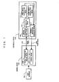
- FIGS. 1 and 2 show a first embodiment.
- Reference number 101 indicates the user interface, which may be a control panel or remote controller of a device.
- Reference number 102 indicates a control device
- 103 indicates a controlled device
- 104 indicates an IEEE 1394 bus interconnecting the control device 102 and the controlled device 103
- reference number 105 indicates a video signal line for transmitting a video signal from the controlled device 103 to the control device 102.
- a specific example may be a combination of a television set and a DVD player connected to it over a network. In this case, the television set is the control device, the DVD player is the controlled device, and a remote controller associated with the television set is the user interface.
- the control device 102 includes control information sending means 106 for providing control information onto the IEEE 1394 bus according to a signal provided from the user interface 101 and a display means 107 for displaying a video signal provided from the controlling information sending means 106 and/or the controlled device 103.
- the information provided from the control information sending means 106 may be superimposed as text or GUI on a video signal provided from the controlled device 103 according to control from the user interface 101 or other elements. It is also possible to display one of an output from the control information sending means 106 and an output from the controlled device 103.
- the controlled device 103 includes control information input means 108 for inputting control information from the IEEE 1394 bus, a selection means 109 for generating a user interface signal for the user to select an element to which the control information provided from the control information input means 108 is applied and for assigning control information to an appropriate functional unit according to the result of the selection by the user first media reproduction means 110 for reproducing a medium according to a control from the selection means 109, second media reproduction means 111 for reproducing a medium according to a control from the selection means 109, and display information generation means 112 for superimposing a display on a reproduction signal provided from the first and second media reproduction means 110 and 111 according to selection information from the selection means 109 and the control information from the control information input means 108.
- the media information reproduction means may be a DVD drive, for example.
- the media reproduction means is a functional unit.
- the video signal line 105 is used in addition to the IEEE 1394. However, it may be transmitted over the IEEE 1394 once a DVD video signal format for IEEE 1394 buses is established.
- a node ID is automatically assigned to each device (unit) connected to the bus during the initialization.
- a device controlling other devices as a controller identifies the devices connected to the bus.
- control device 102 uses the control information sending means 106 to issue a UNIT INFO command defined in the AV/C General.
- the devices connected to the bus select predetermined, typical one of functional units (subunit types) contained in the devices and return it to the control unit 102.
- the control device 102 sends a SUBUNIT INFO command, all subunits and the number of the subunits in the unit are returned.
- the control device 102 can read configuration ROM (not shown) of each unit to know the manufacturer of each device and other information.
- the control device 102 uses the display means 107 to present'the information to the user.
- the user uses the user interface 101 to select a unit to control. In this example, it is assumed that the user selects controlled device 103.
- the user knows that the controlled device 103 has a panel subunit. Therefore, he or she sets the control device 102 so as to display a video signal for the controlled device 103 on the display means 107.
- the video signal is provided through the video signal line 105 and the user uses a video switching function of the user interface 101 to change the input to the display means 107.
- the video signal line 105 may be automatically selected as the input to the display means 107 when it is identified that the controlled device 103 has a panel subunit. If a device made by the same manufacturer as that of a previous device is connected, then its wiring has been made as specified its instruction manual and the wiring can be automatically selected, thereby saving the user the trouble.
- the controlled device 103 outputs information required for the selection means 109 to generate a screen on which one of the first and second media reproduction means 110 and 111 can be selected, as shown in FIG. 2a.
- This screen information is displayed on the display means 107 as shown in FIG. 2a through the display information generation means 112.
- FIG. 2a "DVD A" is highlighted to indicate that the first media reproduction means 110 is selected.
- the user operates the user interface 101.
- the control information sending means 106 issues a pass-through command according to the user's operation.
- control information sending means 106 issues a pass-through command of an operation ID corresponding to the up-arrow or down-arrow key.
- the control information input means 108 receives the pass-through command and transfers control information to the selection means 109.
- the selection means 109 performs a GUI operation according to the control information to move the highlight.
- the control information sending means 106 issues a pass-through command of an operation ID corresponding to "confirmation" performed by a user operation
- the selection means 109 stores, as an object to be controlled, one of the first and second media reproduction means 110 and 111 that is highlighted at the time.
- the object to be controlled in the controlled device 103 is determined.
- selected one of the first and second media reproduction means 110 and 111 outputs screen information for selecting a content, as shown in FIG. 9.
- the screen information is displayed as shown in FIG. 9 on the display means 107 through the display information generation means 112.
- Control information in the pass-through command issued by the control information sending means 106 is transferred to one of the first and second media reproduction means 110 and 111, which is stored in the selection means 109, and screen information for content selection is updated and the content is selected.
- the pass-through command can be specified by any other device operations, besides the GUI operation. If a pass-through command of an operation id for specifying a device operation such as a stop or a pause is sent to the controlled device 103 while a content is selected and being reproduced, it is transferred to one of the first and second media reproduction means 110 and 111 stored in the selection means 109 and the media reproduction is controlled, as with the GUI operation.
- a pass-through command of an operation id for specifying a device operation such as a stop or a pause
- media reproduction means stored in the device previously as a default value may be selected as the object to be controlled.
- the media reproduction means stored in the device it may be determined whether the other media reproduction means contains a medium and, if it contains one, it may be selected as means to be controlled.
- the media reproduction means selected in this way is stored in the selection means 109 and becomes the means to be controlled subsequently.
- a pass-through command of an operation id of a operation on a menu (for example a setup menu defined in the Panel Subunit Specification) is sent to the controlled device 103, the media reproduction means selection screen shown in FIG. 2a is displayed so that a functional unit to be controlled can readily be changed.
- FIG. 2a While the screen for selecting a functional unit to be controlled is shown in FIG. 2a, functional units and their contents may be presented at a time as shown in FIG. 2b. In that case, the user may select a functional unit or a content. If the user selects a content, the functional unit that contains that content is selected, a pass-through command of an operation ID corresponding to "Confirmation" is sent from the control device 102 to the controlled device 103, functional unit selection information is provided and the content is reproduced.
- IEEE 1394 digital interface is used in this embodiment, any other digital interfaces can be used.
- the embodiment can be applied to device control using Bluetooth.
- the controlled device 103 has the selection means 109 allowing a user to select a functional unit to be controlled by using the display means.
- the user selects a functional unit to be controlled and the result of the selection is stored.
- the first embodiment provides the advantage that a command specifying no functional unit that actually performs an operation in the controlled device can be used and yet the command can be applied to a functional unit intended by the user.
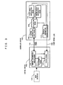
- FIG. 3 shows a second embodiment of the present invention.
- the same elements as those in FIG. 1 are labeled with the same numbers and will be described using those same numbers.
- Reference number 101 indicates a user interface, which may be a remote controller or control panel of a device, for example.
- Reference number 102 indicates a control device
- 103 indicates a controlled device
- 104 indicates an IEEE 1394 bus interconnecting the control device 102 and the controlled device 103
- 105 indicates a video signal line for transmitting a video signal from the controlled device 103 to the control device 102.
- the control device 102 includes control information sending means 106 for providing control information onto the IEEE 1394 bus 104 according to a signal from the user interface 101 and selection means 313, and the selection means 313 that exchanges information with the user interface 101 and control information sending means 106 and provides the result to display means 107, and the display means 107 for displaying video signals provided from the controlled device 103 and the selection means 313 and further from the control information sending means 106.
- Information provided from the control information sending means 106 may be superimposed as text or a GUI.on video signals provided from the controlled unit 103 according to the control provided from the user interface 101 and others. It is also possible that only one of the output from the control information sending means 106 and the output from the controlled device 103 is displayed.
- the controlled device 103 includes control information input means 108 for inputting control information provided from the IEEE 1394 bus, allocation means 309 for allocating the control information provided from the control information input means 108 to each functional unit according to selection by a user, first media reproduction means 110 for reproducing a medium according to the control from the allocation means 309, second media reproduction means 111 for reproducing a medium according to the control form the allocation means 309, and display information generation means 112 for superimposing a display on a reproduction signal provided from the first and second media reproduction means 110 and 111 according to selection information provided from the allocation means 309 and control information provided from the control information input means 108.
- the media information reproduction means may be a DVD drive, for example.
- the video signal line 105 is used in addition to the IEEE 1394. However, it may be transmitted over the IEEE 1394 once a DVD video signal format for IEEE 1394 buses is established.
- a procedure from bus initialization until a user selects a device (unit) to control is the same as that in the first embodiment.
- the control device 102 reads configuration ROM (not shown) to identify the manufacturer of a devices.
- configuration ROM 64-bit identifiers called EUI (Extended Unique Identifier) 64 that can uniquely identify devices throughout the world can also be read.
- EUI 64 Extended Unique Identifier
- Upper 24 bits of an EUI 64 represent a manufacturer identifier assigned by IEEE to each manufacturer and lower 40 bits represent a unique code assigned by the manufacturer to ensure uniqueness.
- control device 102 can compare the value of an EUI 64 read from a controlled device 103 with the EUI 64 of a device having the configuration of the controlled device 103, which has been stored beforehand, to determine whether the unit to be controlled has the configuration of the controlled device 103.
- the selection means 313 outputs information for generating an initial screen, which is a screen for selecting one of the first and second media reproduction means 110 and 111, as shown in FIG. 2a. This screen information is displayed on the display means 107 as shown in FIG. 2a.
- FIG. 2a "DVD A" is highlighted to indicate the first media reproduction means 110 is selected.
- a user operates the user interface 101. Because the currently displayed screen has been generated by the control device 102 itself, the control device 102 determines that the operation on the user interface 101 is directed to it and does not issue any pass-through command.
- the selection means 313 moves the highlight in response to an up-arrow or down-arrow key operation, when "confirmation" is selected by the user, the selection means 313 stores one of the first and second media reproduction means 110 and 111 that is currently highlighted, as the object to be controlled. Then the result of the determination is sent from the control information output means 106 through the IEEE 1394 bus 104 and'the control information input means 108 to the allocation means 309 and stored there.
- the functional unit to be controlled is determined and subsequently a video signal provided from the controlled device 103 is displayed on the display means 107.
- a subsequent operation on the user interface 101 will be sent as a pass-through command from the control information sending means 106 to the controlled device 103. In this way, the object to be controlled in the controlled device 103 is determined.
- the selected one of the first and second media reproduction means 110 and 111 outputs screen information for selecting a content, as shown in FIG. 9, which has been described with respect to the example of prior art.
- This screen information is displayed as shown in FIG. 9 on the display means 107 through the display information generation means 12.
- the user operates the user interface 101 to selects a content.
- Control information in a pass-through command sent by the control information sending means 106 is transferred to the first or second media reproduction means 110 or 111 depending on the information stored in the allocation means 309, and the content selection screen information is updated and a content is selected.
- the pass-through command can be specified by any other device operations, besides the GUI operation. If a pass-through command of an operation id for specifying a device operation such as a stop and a pause is sent to the controlled device 103 while a content is selected and being reproduced, it is transferred to one of the first and second media reproduction means 110 and 111 stored in the selection means 309 and the media reproduction is controlled, as with the GUI operation.
- a pass-through command of an operation id for specifying a device operation such as a stop and a pause
- a pass-through command of an operation id specifying a device.operation is sent to the controlled device 103 before a media reproduction means is selected, a media reproduction means stored previously in the device as a default value may be selected as the item to be controlled.
- the media reproduction means stored in the device it may be determined whether the other media reproduction means contains a medium and, if it contains one, it may be selected as means to be controlled.
- the media reproduction means selected in this way is stored in the selection means 309 and becomes the means. to be controlled subsequently.
- control device 102 again displays the media reproduction means selection screen shown in FIG. 2a so that a functional unit to be controlled can be readily changed.
- IEEE 1394 digital interface is used in this embodiment, any other digital interfaces can be used.
- the embodiment can be applied to device control using Bluetooth.
- the control device has the selection means allowing a user to select a functional unit to be controlled by using the display means.
- the user selects a functional unit to be controlled and the result of the selection is stored in the controlled unit.
- the second embodiment provides the advantage that a command specifying no functional unit that actually performs an operation in the controlled device can be used and yet the command can be applied to a functional unit intended by the user.
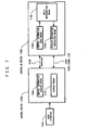
- FIGS. 4 and 5 show a third embodiment.
- the same elements as those in FIG. 1 are labeled with the same numbers and will be described using those same numbers.
- Reference number 101 indicates a user interface, which may be a remote controller or control panel of a device, for example.
- Reference number 102 indicates a control device
- 103 indicates a controlled device
- 104 indicates an IEEE 1394 bus interconnecting the control device 102 and the controlled device 103
- 105 indicates a video signal line for transmitting a video signal from the controlled device 103 to the control device 102.
- the control device 102 includes control information sending means 106 for providing control information onto the IEEE 1394 bus 104 according to a signal provided from the user interface 101 and display means 107 for displaying video signals provided from the controlled device 103 and the control information sending means 106.
- the information from the control information sending means 106 may be superimposed as text or a GUI on the video signal provided from the controlled device 103 or one of the information and the video signal may be displayed, depending on control form the user interface 101.
- the controlled device 103 includes control information input means 108 for inputting control information from the IEEE 1394 bus, allocation means for allocating the control information inputted from the control information input means 107 to each functional unit according to control information provided from switching means 414, a first media reproduction means 110 for reproducing a medium according to the control from the allocation means 409, a second media reproduction means 111 for reproducing a medium according to the control form the allocation means 409, the switching means 414 for switching between reproduction signals provided from the first and second media reproduction means 110 and 111 according to the control information.provided from the control information input means 108, and display information generation means 112 for outputting a signal provided from the switching means 414 as a video signal.
- the media information reproduction means may be a DVD drive., for example.
- the video signal line 105 is used in addition to the IEEE 1394. However, it may be transmitted over the IEEE 1394 once a DVD video signal format for IEEE 1394 buses is established.
- a procedure from bus initialization until a user selects a device (unit) to control is the same as that in the first embodiment.
- the switching means 414 selects an output signal, which is a default value, immediately after the controlled device 103 is turned on.
- One of the first and second media reproduction means may be predefined as a default, or a media reproduction means previously used and stored may be selected as the default.
- a CONNECT command is issued from the control device 102.
- the CONNECT command is defined in AV/C General as a command for controlling plug connection of a subunit and unit.
- a plug herein refers to a virtual signal . terminal defined in IEEE 1394.
- Each of the first and second media reproduction means 110 and 111 has one source plug and outputs a signal through the plug.
- the controlled device 103 has one external output plug and outputs a video signal to an external destination.
- FIG. 5 shows a format of the CONNECT command. In FIG. 5, operand [1] and operand [2] indicate signal sources and [3] and [4] indicate destinations.
- Source_subunit_type combined with source_subunit_ID fields specifies a subunit as a signal source.
- Source_plug field specifies the number.of a plug.
- a combination of destination_subunit_type field and destination_subunit_ID field specifies a subunit as a destination destination_plug field specifies the number of a plug. If "1F" is contained in the subunit_type field, it indicates a unit and can specify a plug, that is, an external output plug of the unit. "3F" in operand [0] indicates a fixed value (all bits are 1). If 1 is contained in a lock field, controlled device 103 rejects any CONNECT command that breaks a stream between plugs specified by operands [1] through [4].
- the connect command allows the switching means 414 to select between signals from the first and second media reproduction means to output a selected signal to an external destination.
- the allocation means 409 selects media reproduction means outputting the selected signal as the element to be controlled.
- the selected one of the first media reproduction means 110 or the second media reproduction mean s111 outputs screen information for selecting a content, as described with respect to the example of prior art and shown in FIG. 9.
- the screen information is presented on the display means 107 through the display information generation means 112, as shown in FIG. 9.
- the user operates the user interface 101 to select a content.
- Control information in a pass-through command issued by the control information sending means 106 is transferred by the allocation means 409 to either the first media reproduction means 110 or the second media reproduction means 111, the content selection screen is updated and a content is selected.
- the pass-through command can be specified by any other device operations, besides the GUI operation. If a pass-through command of an operation id for specifying a device operation such as a stop or a pause is sent to the controlled device 103 while a content is selected and is being reproduced, it is transferred to one of the first and second media reproduction means 110 and 111 stored in the allocation means 409 and the media reproduction is controlled, as with the GUI operation.
- a pass-through command of an operation id for specifying a device operation such as a stop or a pause
- a functional unit outputting a signal is controlled in this embodiment, a functional unit inputting a signal in a recording device can also be controlled.
- media reproduction means that is stored in the controlled devices as a default and outputs a signal to an external destination, it may be determined whether another media reproduction means contains a medium and, if it contains one, that media reproduction means may be selected as the object to be controlled.
- the control device controls a functional unit selected by the user as a signal source.
- the third embodiment provides the advantage that a command specifying no functional unit that actually operates in the controlled device can be used and yet the command can be applied to a functional unit intended by the user.
- a functional unit is selected on an instruction from the control device 102 in the third embodiment. However, if switching means is provided in the controlled device 103, a functional unit may be selected on an instruction from the switching means in.the controlled device 103, rather than a instruction from the control device 102.
- reproduction outputs from the first and second media reproduction means 110 and 111 are provided to the control device 102 through the switching means 414 in this embodiment, an arrangement may be possible in which the reproduction outputs are provided to a device other than the control device 102 through the switching means 414.
- IEEE 1394 digital interface is used in this embodiment, any other digital interfaces can be used.
- the embodiment can be applied to device control using Bluetooth.
- the controlled device has a selection means allowing a user to select a functional unit to be controlled, the user selects the functional unit to be controlled, and the selection is stored.
- the present invention provides the advantage that a command specifying no functional unit that actually operates in the controlled device can be used and yet the command can be applied to a functional unit intended by the user.
- the control device has the selection means allowing a user to select a functional unit to be controlled.
- the user selects a functional unit to be controlled and the result of the selection is stored in the controlled unit.
- the control device controls a functional unit selected by the user as a signal source.
- the present invention provide the advantage that a command specifying no functional unit that actually operates in the controlled device can be used and yet the command can be applied to a functional unit intended by the user.
Applications Claiming Priority (3)
| Application Number | Priority Date | Filing Date | Title |
|---|---|---|---|
| JP2000324783 | 2000-10-25 | ||
| JP2000324783 | 2000-10-25 | ||
| PCT/JP2001/008779 WO2002035881A1 (fr) | 2000-10-25 | 2001-10-04 | Dispositif commande et dispositif de commande dans un appareil de reseau, ainsi que procede de commande de ceux-ci |
Publications (2)
| Publication Number | Publication Date |
|---|---|
| EP1328134A1 true EP1328134A1 (fr) | 2003-07-16 |
| EP1328134A4 EP1328134A4 (fr) | 2009-06-17 |
Family
ID=18802252
Family Applications (1)
| Application Number | Title | Priority Date | Filing Date |
|---|---|---|---|
| EP01972703A Withdrawn EP1328134A4 (fr) | 2000-10-25 | 2001-10-04 | Dispositif commande et dispositif de commande dans un appareil de reseau, ainsi que procede de commande de ceux-ci |
Country Status (4)
| Country | Link |
|---|---|
| US (1) | US20040215352A1 (fr) |
| EP (1) | EP1328134A4 (fr) |
| JP (1) | JPWO2002035881A1 (fr) |
| WO (1) | WO2002035881A1 (fr) |
Families Citing this family (5)
| Publication number | Priority date | Publication date | Assignee | Title |
|---|---|---|---|---|
| JPWO2002056548A1 (ja) * | 2001-01-16 | 2004-05-20 | ソニー株式会社 | データ伝送方法、データ伝送装置、記録媒体及びプログラム |
| JP4116390B2 (ja) * | 2002-10-07 | 2008-07-09 | シャープ株式会社 | 機器コントロールシステム、表示装置及び機器コントロールプログラムを記録した記録媒体 |
| JP4557662B2 (ja) * | 2004-10-01 | 2010-10-06 | シャープ株式会社 | Av機器 |
| JP2010176494A (ja) * | 2009-01-30 | 2010-08-12 | I-O Data Device Inc | 脱着式複合デバイス |
| US10401816B2 (en) * | 2017-07-20 | 2019-09-03 | Honeywell International Inc. | Legacy control functions in newgen controllers alongside newgen control functions |
Citations (1)
| Publication number | Priority date | Publication date | Assignee | Title |
|---|---|---|---|---|
| WO1996035152A1 (fr) * | 1995-05-04 | 1996-11-07 | Elonex Technologies, Inc. | Systeme de telecommande de fonctions pour des peripheriques informatiques |
Family Cites Families (16)
| Publication number | Priority date | Publication date | Assignee | Title |
|---|---|---|---|---|
| JPH05168065A (ja) * | 1991-12-16 | 1993-07-02 | Mitsubishi Electric Corp | リモコン送信器 |
| JPH05244665A (ja) * | 1992-02-27 | 1993-09-21 | Onkyo Corp | 電子機器の遠隔制御システム |
| CN100545828C (zh) * | 1993-07-30 | 2009-09-30 | 佳能株式会社 | 控制连接到网络的网络设备的控制设备及其控制方法 |
| KR0164089B1 (ko) * | 1995-12-20 | 1998-12-01 | 양승택 | 무선원격제어 장치 및 방법 |
| EP1002406B1 (fr) * | 1997-06-25 | 2005-01-19 | Samsung Electronics Co. Ltd. | Generation de guide de programmes pour reseaux domestiques |
| IL139408A0 (en) * | 1998-05-07 | 2001-11-25 | Samsung Electronics Co Ltd | Method and apparatus for user and device command and control in a network |
| US6219839B1 (en) * | 1998-05-12 | 2001-04-17 | Sharp Laboratories Of America, Inc. | On-screen electronic resources guide |
| US7865832B2 (en) * | 1999-07-26 | 2011-01-04 | Sony Corporation | Extended elements and mechanisms for displaying a rich graphical user interface in panel subunit |
| US6381507B1 (en) * | 1998-07-01 | 2002-04-30 | Sony Corporation | Command pass-through functionality in panel subunit |
| US6295479B1 (en) * | 1998-07-01 | 2001-09-25 | Sony Corporation Of Japan | Focus in/out actions and user action pass-through mechanism for panel subunit |
| JP2000174782A (ja) * | 1998-12-03 | 2000-06-23 | Matsushita Electric Ind Co Ltd | 機器制御装置及び機器被制御装置 |
| CN1386390A (zh) * | 2000-05-22 | 2002-12-18 | 索尼公司 | 数据传送方法、数据传送系统及数据传送装置 |
| JP4396011B2 (ja) * | 2000-08-22 | 2010-01-13 | ソニー株式会社 | 情報制御方法、情報処理装置および情報制御システム |
| JPWO2002056548A1 (ja) * | 2001-01-16 | 2004-05-20 | ソニー株式会社 | データ伝送方法、データ伝送装置、記録媒体及びプログラム |
| US20020194596A1 (en) * | 2001-06-18 | 2002-12-19 | Srivastava Gopal K. | Control of multiple AV-devices by a single master controller using infrared transmitted commands and bus transmitted commands |
| WO2003065199A1 (fr) * | 2002-01-29 | 2003-08-07 | Matsushita Electric Industrial Co., Ltd. | Procede de transmission de donnees d'impression, systeme d'impression et imprimante |
-
2001
- 2001-10-04 EP EP01972703A patent/EP1328134A4/fr not_active Withdrawn
- 2001-10-04 JP JP2002538715A patent/JPWO2002035881A1/ja active Pending
- 2001-10-04 WO PCT/JP2001/008779 patent/WO2002035881A1/fr active Application Filing
- 2001-10-04 US US10/148,260 patent/US20040215352A1/en not_active Abandoned
Patent Citations (1)
| Publication number | Priority date | Publication date | Assignee | Title |
|---|---|---|---|---|
| WO1996035152A1 (fr) * | 1995-05-04 | 1996-11-07 | Elonex Technologies, Inc. | Systeme de telecommande de fonctions pour des peripheriques informatiques |
Non-Patent Citations (1)
| Title |
|---|
| See also references of WO0235881A1 * |
Also Published As
| Publication number | Publication date |
|---|---|
| US20040215352A1 (en) | 2004-10-28 |
| JPWO2002035881A1 (ja) | 2004-03-11 |
| WO2002035881A1 (fr) | 2002-05-02 |
| EP1328134A4 (fr) | 2009-06-17 |
Similar Documents
| Publication | Publication Date | Title |
|---|---|---|
| EP0849884B1 (fr) | Récepteurs et méthodes de télécommande et système de télécommande | |
| EP1016271B1 (fr) | Appareil de television numerique permettant de controler un peripherique via un bus numerique | |
| US7072991B2 (en) | Audio visual system having a serial bus for identifying devices connected to the external terminals of an amplifier in the system | |
| JPH09154077A (ja) | 複数のav機器と接続したディスプレイ装置からなるavシステム | |
| EP1328134A1 (fr) | Dispositif commande et dispositif de commande dans un appareil de reseau, ainsi que procede de commande de ceux-ci | |
| JP2003110961A (ja) | 映像表示制御方法及び映像機器 | |
| JP3952053B2 (ja) | 接続管理プログラム | |
| JP2001243676A (ja) | 情報処理装置及び方法、媒体 | |
| JP2001298676A (ja) | 映像再生装置、映像表示装置、及び操作制御システム並びに操作制御方法 | |
| JP4277389B2 (ja) | 制御情報送受信方法 | |
| JP2000174782A (ja) | 機器制御装置及び機器被制御装置 | |
| JP3862537B2 (ja) | ネットワーク機器制御装置ならびに被制御装置および制御方法 | |
| KR100763716B1 (ko) | 정보 제어 방법, 정보 처리 장치, 및 정보 제어 시스템 | |
| US20010046231A1 (en) | Communication control apparatus | |
| EP1102486B1 (fr) | Système de contrôle pour un reseau et contrôleur et dispositif utilisé là-dedans | |
| EP1521259A1 (fr) | Dispositif et procede d'enregistrement d'informations | |
| JP4635290B2 (ja) | 制御方法及び表示装置 | |
| JP2003078537A (ja) | 機器認識方法及び電子機器 | |
| JP2000295674A (ja) | 遠隔制御装置、被遠隔制御装置および遠隔制御システム | |
| JP4652584B2 (ja) | 制御装置、方法およびプログラム | |
| JP2000356980A (ja) | 映像表示方法、映像表示装置及び映像出力装置 | |
| JP2004229079A (ja) | 被制御機器 | |
| JP2001025074A (ja) | 情報処理システム、電子機器、及び情報処理方法 | |
| MXPA00002741A (en) | Peripheral electronic device and system for controlling this device via a digital bus |
Legal Events
| Date | Code | Title | Description |
|---|---|---|---|
| PUAI | Public reference made under article 153(3) epc to a published international application that has entered the european phase |
Free format text: ORIGINAL CODE: 0009012 |
|
| 17P | Request for examination filed |
Effective date: 20020626 |
|
| AK | Designated contracting states |
Designated state(s): AT BE CH CY DE DK ES FI FR GB GR IE IT LI LU MC NL PT SE TR |
|
| RBV | Designated contracting states (corrected) |
Designated state(s): DE FR GB |
|
| RAP1 | Party data changed (applicant data changed or rights of an application transferred) |
Owner name: PANASONIC CORPORATION |
|
| A4 | Supplementary search report drawn up and despatched |
Effective date: 20090514 |
|
| RIC1 | Information provided on ipc code assigned before grant |
Ipc: G08C 17/00 20060101AFI20090508BHEP |
|
| 17Q | First examination report despatched |
Effective date: 20091102 |
|
| STAA | Information on the status of an ep patent application or granted ep patent |
Free format text: STATUS: THE APPLICATION IS DEEMED TO BE WITHDRAWN |
|
| 18D | Application deemed to be withdrawn |
Effective date: 20100313 |