EP1324513A2 - Empfänger, Sender, Kommunikationssystem, und Kommunikationsverfahren - Google Patents
Empfänger, Sender, Kommunikationssystem, und Kommunikationsverfahren Download PDFInfo
- Publication number
- EP1324513A2 EP1324513A2 EP02029102A EP02029102A EP1324513A2 EP 1324513 A2 EP1324513 A2 EP 1324513A2 EP 02029102 A EP02029102 A EP 02029102A EP 02029102 A EP02029102 A EP 02029102A EP 1324513 A2 EP1324513 A2 EP 1324513A2
- Authority
- EP
- European Patent Office
- Prior art keywords
- sub
- antenna
- carrier
- weights
- weight
- Prior art date
- Legal status (The legal status is an assumption and is not a legal conclusion. Google has not performed a legal analysis and makes no representation as to the accuracy of the status listed.)
- Granted
Links
Images


Classifications
-
- H—ELECTRICITY
- H04—ELECTRIC COMMUNICATION TECHNIQUE
- H04B—TRANSMISSION
- H04B1/00—Details of transmission systems, not covered by a single one of groups H04B3/00 - H04B13/00; Details of transmission systems not characterised by the medium used for transmission
- H04B1/69—Spread spectrum techniques
- H04B1/707—Spread spectrum techniques using direct sequence modulation
-
- H—ELECTRICITY
- H04—ELECTRIC COMMUNICATION TECHNIQUE
- H04B—TRANSMISSION
- H04B7/00—Radio transmission systems, i.e. using radiation field
- H04B7/02—Diversity systems; Multi-antenna system, i.e. transmission or reception using multiple antennas
- H04B7/04—Diversity systems; Multi-antenna system, i.e. transmission or reception using multiple antennas using two or more spaced independent antennas
- H04B7/08—Diversity systems; Multi-antenna system, i.e. transmission or reception using multiple antennas using two or more spaced independent antennas at the receiving station
- H04B7/0837—Diversity systems; Multi-antenna system, i.e. transmission or reception using multiple antennas using two or more spaced independent antennas at the receiving station using pre-detection combining
- H04B7/0842—Weighted combining
Definitions
- the present invention relates to a receiver, a transmitter, a communication system, and a method of communication.
- CDMA code division multiple access
- the multi-carrier CDMA transmission method is a method of transmission in which a data symbol is copied in the direction of a frequency axis; each of the copied data symbols is multiplied by one chip of a spreading code and spread; and the spread data signals are transmitted in parallel over a plurality of sub-carriers having different frequencies.
- the multi-carrier CDMA transmission method makes it possible to transmit a plurality of data symbols simultaneously.
- a data symbol is multiplied by a spreading code in the direction of a frequency axis. Therefore, according to the multi-carrier CDMA transmission method, a plurality of data symbols can be code-division-multiplexed by multiplying the data symbols by a spreading code orthogonal to each other.
- the multi-carrier CDMA transmission method makes it possible to reduce the influence of so-called multipath interference that is problematic in a mobile communication environment.
- Multipath interference is interference which occurs between transmission signals when they arrive at a receiver at different timing via a plurality of different paths (a multipath) and which results in the degradation of signal transmission characteristics.
- a multipath frequency-selective fading occurs in which variations in the path occurs depending on frequency, the signal transmission characteristic varying depending on its frequency.
- a data signal is spread in the direction of a frequency axis. Therefore, according to the multi-carrier CDMA transmission method, a frequency diversity effect reduces the influence of variation in signal transmission characteristic, thus improving signal transmission characteristics.
- the multi-carrier CDMA transmission method has many advantages as thus described.
- a receiver receives signals that are signals over a data channel #1 and a data channel #2 multiplexed and transmitted.
- the receiver multiplies the reception signals by a spreading code in the direction of frequencies, the spreading code being identical to a spreading code that has been multiplied at the transmitter.
- the receiver performs despreading by combining the reception signals of each sub-carrier over the spreading code duration of the spreading codes.
- the spreading codes multiplied on the data symbols in the respective data channels are orthogonal to each other. Therefore, the data symbols in the respective data channels #1 and #2 are completely recovered in the reception signals after despreading.
- the propagation path variation value will not have a constant. Therefore, the orthogonality of the spreading codes multiplied on the reception signals in the respective data channels received after propagating on the multipath is destructed. As a result, the data symbols in the respective data channels #1 and #2 can be not completely recovered from the reception signals after despreading, and the data symbols in the data channels interfere with each other and remain, which degrades signal transmission characteristics.
- Diversity combining is a technique for reducing the influence of variation in signal transmission characteristics depending on frequency by the above-described effect of frequency-selective fading, and improving signal transmission characteristics.
- One scheme for diversity combining is antenna diversity combining in which signals are received by a plurality of antennas and in which combining is performed with the signal received of each of the antennas multiplied by weights.
- a method for weighting in antenna diversity combining has been proposed in Linear Diversity Combining Techniques (D. G. Brennan, Proc. IRE, pp. 1075-1102, VOL. 47, NO. 6, June 1959).
- An object of the present invention is to apply appropriately antenna diversity combining to the multi-carrier CDMA transmission method to reduce the influence of interference between data channels and to thereby improve signal transmission characteristics.
- a receiver comprises a plurality of antennas configured to receive signals that are obtained by multiplying a plurality of data symbols transmitted over a plurality of data channels using spreading codes for each of the data channels, the data symbol being transmitted over a plurality of sub-carriers having different frequencies, a spreading code multiplier configured to multiply the reception signals received by the plurality of antennas using spreading codes for the data channels corresponding to the reception signals, a weight controller configured to adjust antenna weights by which the reception signal received by each antenna is to be multiplied and sub-carrier weights by which the reception signal received over each sub-carrier is to be multiplied, a weight multiplier configured to multiply the reception signals by the antenna weights and the sub-carrier weights adjusted by the weight controller, and a combining unit configured to combine the reception signals multiplied by the antenna weights and the sub-carrier weights at the weight multiplier among the antennas and over the spreading code duration of the spreading codes.
- the plurality of antennas receive signals that are obtained by multiplying a plurality of data symbols using spreading codes for each of the data channels and that are transmitted over a plurality of sub-carriers having different frequencies.
- the spreading code multiplier multiplies the reception signals using spreading codes for the data channels corresponding to the reception signals.
- the weight multiplier multiplies the reception signals by the antenna weights which is adjusted by the weight controller and by which the signal received by each antenna is multiplied and sub-carrier weights which is adjusted by the weight controller and by which the signal received over each sub-carrier is multiplied.
- the combining unit combines the reception signals multiplied by the antenna weights and sub-carrier weights among the antennas and over the spreading code duration of the spreading codes.
- the reception signals are multiplied by the antenna weights and sub-carrier weights adjusted by the weight controller. Therefore, the spreading codes for each of the data channels which the reception signals are multiplied are orthogonal to each other. As a result, the data symbols are less affected by interference between the data channels that is caused by the destruction of orthogonality between the spreading codes. As thus described, the receiver can improve the signal transmission characteristics by appropriately applying antenna diversity combining to the multi-carrier CDMA transmission method.
- a communication system 1 comprises a transmitter 4 and a receiver 5.
- the transmitter 4 is provided at a base station 2, for example.
- the receiver 5 is provided in a terminal apparatus 3, for example.
- the transmitter 4 transmits signals using the multi-carrier CDMA transmission method in which signals obtained by multiplying a plurality of data symbols transmitted on a plurality of data channels by a spreading code are transmitted over a plurality of sub-carriers having different frequencies.
- the receiver 5 receives the signals transmitted by the transmitter 4 according to the multi-carrier CDMA transmission method.
- the communication system is not limited to one-to-one communication between the transmitter 4 and the receiver 5 as shown in Fig.
- a communication system may be employed which allows communication between one transmitter 4 and a plurality of receivers 5, communication between a plurality of transmitters 4 and one receiver 5, or communication between a plurality of transmitters 4 and a plurality of receivers 5.
- the communication system may be a communication system in which a transmitter 4 or receiver 5 relays a signal to another transmitter 4 or receiver 5.
- the transmitter 4 comprises a plurality of signal processing unit 41 1 to 41n, a pilot symbol inserting unit 41h, a signal combining unit 42, a frequency/time converter 43, a guard interval inserting unit 44, and an antenna 45.
- the signal processing units 41 1 to 41n are provided in the same quantity as a plurality of data channels #1 to #n.
- the signal processing units 41 1 to 41n associated with the data channels #1 to #n process transmission signals such as data signals and pilot signals transmitted over the data channels #1 to #n.
- the signal processing units 41 1 to 41n comprise a data symbol generating unit 41a, an error-correction-encoder 41b, a data modulator 41c, a serial/parallel converter 41d, a spreading code generating unit 41e, a plurality of symbol copier 41f, and a plurality of spreading code multiplier 41g.
- the data symbol generating unit 41a generates data symbols to be transmitted over the data channels associated therewith. Specifically, the data symbol generating units 41a of the respective signal processing units 41 1 to 41n generate data symbols associated with the respective data channels #1 to #n. The data symbol generating unit 41a generates data symbols of data such as images and sounds to be transmitted to the terminal apparatus 3. For example, data symbol generating circuit that generates data symbols may be used as the data symbol generating unit 41a.
- the error-correction-encoder 41b perform error-correction encoding on data symbols generated by the data symbol generating units 41a.
- the error-correction-encoder 41b performs turbo encoding or convolutional encoding, for example.
- the receiver 5 can perform error-correction-decoding. Therefore, the receiver 5 can obtain an encoding gain (a quantity of improvement that is a reduction in power required for reception achieved by applying an error-correcting encoding) to improve communication quality.
- the data modulator 41c performs a data modulating process on a data symbol that has been subjected to error-correction-encoding.
- the data modulator 41c performs multivalued quadrature amplitude modulation (QAM) such as 16-QAM and 64-QAM, binary phase shift keying (BPSK) modulation, or quadrature phase shift keying (QPSK) modulation.
- QAM quadrature amplitude modulation
- BPSK binary phase shift keying
- QPSK quadrature phase shift keying
- the serial/parallel converter 41d is a divider configured to divide a data symbol into a plurality of data symbols.
- the serial/parallel converter 41d performs serial/parallel conversion of a data symbol in order to transmit a plurality of data symbols at the same time. Specifically, the serial/parallel converter 41d divide a serial data symbol input from the data modulator 41c at constant intervals, converting it into data symbols that are arranged in parallel in the direction of a frequency axis.
- the symbol copiers 41f copy the plurality of data symbols obtained by the serial/parallel conversion and division at the serial/parallel converter 41d in a quantity that is equal to a number of spreading code duration of the spreading codes corresponding to the data channels #1 to #n over which the data symbols are transmitted.
- the spreading code generating unit 41e generates the spreading codes corresponding to the respective data channels and assigned to the data channels.
- the spreading code generating unit 41e inputs the generated spreading codes to the spreading code multiplier 41g.
- the spreading code multipliers 41g multiply the data symbols copied by the symbol copiers 41f using the spreading codes corresponding to the data channels #1 to #n over which the data symbols are transmitted to provide data signals.
- the spreading code multipliers 41g multiply the respective copied data symbols using the spreading codes input thereto from the spreading code generating unit 41e in the direction of the frequency axis.
- the spreading code multipliers 41g are provided in a quantity that is equal to the number of the spreading code duration of the spreading codes corresponding to the data channels #1 to #n over which the data symbols are transmitted.
- The. spreading code multipliers 41g input the data signals obtained by multiplying the data symbols using the spreading codes to the signal combining unit 42.
- the pilot symbol inserting unit 41h inserts pilot symbol into the data symbols to generate transmission signals 6 that are data signals multiplexed with pilot signals.
- the pilot symbol is symbol whose amplitude and phase are known to the receiver 5.
- the pilot symbol is used by the receiver 5 to estimate propagation path variation in the reception signal and an error between a reception signal and a transmission signal after despreading.
- pilot symbols may be used in the plurality of data channels #1 to #n, and different pilot symbols may alternatively be used in each of the data channels #1 to #n.
- Propagation path variation is variation in the phase and amplitude of a signal transmitted by the transmitter 4 that occur on the same when it is propagated in a propagation path between the transmitter 4 and the receiver 5 before it is received by the receiver 5. That is, propagation path variation indicates how much the phase and amplitude of a signal transmitted by the transmitter 4 changes before it is received by the receiver 5 after being propagated in a propagation path between the transmitter 4 and the receiver 5.
- Such estimation of a propagation path variation in a reception signal is referred to as "channel estimation”. Therefore, propagation path variation in a reception signal obtained through channel estimation is specially called "channel estimated value”.
- the transmitter 4 performs code-division-multiplexing in order to multiplex pilot signals and data signals in the direction of a spreading code axis.
- the pilot signal inserting unit 41h provides the signal combining unit 42 with the input of pilot signals obtained by multiplying pilot symbols using spreading codes different from those of the signal processing units 41 1 to 41n as well as the signal processing units 41 1 to 41n of the plurality of data channels #1 to #n.
- the term "insertion of pilot symbols” implies not only inserting pilot symbols as they are but also inserting pilot symbols after converting them into pilot signals by multiplying them using spreading codes.
- the signal combining unit 42 combines the data signals in the respective data channels #1 to #n input from the spreading code multiplier 41g of the signal processing units 41 1 to 41n of the respective data channels, thereby code-division-multiplexing the same. Not only the data signals of the respective data channels #1 to #n but also the pilot signals are input to the signal combining unit 42 of the transmitter 4 by the pilot symbol inserting unit 41h. Therefore, the signal combining unit 42 combines the data signals and pilot signals to perform code-division-multiplexing on the same.
- the frequency/time converter 43 is a spreading unit configured to spread the data signals multiplied using spreading codes at the spreading code multiplier 41g and code-division-multiplexed by the signal combining unit 42 over a plurality of sub-carriers having different frequencies for transmitting the data signals.
- the frequency/time converter 43 performs frequency/time signal conversion on the data signals to assign the data signals to the plurality of sub-carriers having different frequencies, thereby generating a multi-carrier CDMA signal.
- an inverse fast Fourier transform (IFFT) apparatus may be used as the frequency/time converter 43 to perform an inverse fast Fourier transform process.
- the guard interval inserting unit 44 inserts a guard interval in each of the data signals spread over the plurality of sub-carriers by the frequency/time converter 43.
- the guard interval is inserted between the data signals to prevent interference between the data signals.
- the insertion of the guard intervals makes it possible to reduce the influence of interference between the data signals that is attributable to a delay of each data signal in arriving at the receiver 5 as a result of multipath propagation.
- the guard interval inserting unit 44 may insert a signal obtained by copying a part of the waveform of a data signal or a signal having a predetermined pattern, for example.
- the length of a guard interval may be determined taking the delay time into consideration.
- the antenna 45 transmits a multi-carrier CDMA signal having guard intervals inserted therein to the receiver 5 as a transmission signal 6. Since pilot signals and data signals have been code-division-multiplexed at the transmitter 4, there is provided a transmission signal 6a in which pilot signals 62a and data signals 61a are code-division-multiplexed with different spreading codes in the direction of a spreading code axis as shown in Fig. 4A.
- the transmission signal 6a is a multi-carrier CDMA signal that is spread in the direction of the frequency axis or spread over the frequencies of a plurality of sub-carriers.
- Pilot signals and data signals may be multiplexed through time-division-multiplexing that is multiplexing in the direction of a time axis.
- a transmitter 204 as shown in Fig. 5 may be used.
- pilot signals and data signals are time-division-multiplexed.
- data symbol generating unit 41a, error-correction-encoder 41b, data modulator 41c, and spreading code generating unit 41e of respective signal processing units 241 1 to 241n, a frequency/time converter 43, a guard interval inserting unit 44, and an antenna 45 are substantially the same as those of the transmitter 4 shown in Fig. 3. Therefore, in Fig. 5 they are indicated by like symbols to those for the transmitter 4 and will not be described here.
- the pilot symbol inserting unit 241h inputs pilot symbols to the serial/parallel converter 241d at different times to when the data modulator 41c inputs data symbols to the serial/parallel converter 241d.
- the data symbols and the pilot symbols are time-division-multiplexed.
- the data symbols output by the data modulator 41c and the pilot symbols output by the pilot symbol inserting unit 241h are input to the serial/parallel converter 241d at different times by switching unit 241i that input the data symbols and the pilot symbols to the serial/parallel converter 241d on a switched basis.
- the serial/parallel converter 241d performs serial/parallel conversion on the time-division-multiplexed data symbols and pilot symbols similarly to the serial/parallel converter 41d.
- Symbol copiers 241f copies the time-division-multiplexed data symbols and pilot symbols similarly to the symbol copier 41f.
- Spreading code multipliers 241g multiply the time-division-multiplexed data symbols and pilot symbols using spreading codes similarly to the spreading code multipliers 41g to provide time-division-multiplexed data signals and pilot signals.
- the spreading code multipliers 241g of the respective data channels #1 to #n input the data signals and pilot signals which have been multiplied using the spreading codes and time-division-multiplexed to a signal combining unit 242.
- the signal combining unit 242 combines the time-division-multiplexed data signals and pilot signals in the respective data channels #1 to #n input from the spreading code multipliers 241g of the signal processing units 241 1 to 241n of the respective data channels to perform code-division-multiplexing on the same.
- a transmission signal 6b transmitted by the transmitter 204 is a transmission signal in which pilot signals 62b and data signals 61b are time-division-multiplexed in the direction of the time axis as shown in Fig. 4B. Since time-division-multiplexed data signals and pilot signals are multiplied using spreading codes to be code-division-multiplexed, the transmission signal 6c becomes a multi-carrier CDMA signal in which the pilot signals 62b are code-division-multiplexed as well as the data signals 61b. Thus, when the pilot signals 62b and the data signals 61b are time-division-multiplexed, no inter-code interference occurs between the pilot signals 62b as shown in Fig. 4B. Therefore, estimation accuracy of the receiver 5 can be improved for estimating the propagation path variation and error between a reception signal and a transmission signal 6 after despreading using pilot signals 62b thus received.
- Pilot signals and data signals may be multiplexed through frequency-division-multiplexing that is multiplexing in the direction of a frequency axis.
- frequency-division-multiplexing for example, a transmitter 304 as shown in Fig. 7 may be used.
- pilot signals and data signals are frequency-division-multiplexed.
- data symbol generating unit 41a error-correction-encoder 41b, data modulator 41c, serial/parallel converter 41d, spreading code generating units 41e, symbol copiers 41f of respective signal processing units 341 1 to 341n, a frequency/time converter 43, a guard interval inserting unit 44, and an antenna 45 are substantially the same as those of the transmitter 4 shown in Fig. 3. Therefore, in Fig. 7 they are indicated by like symbols to those for the transmitter 4 and will not be described here.
- Pilot symbol inserting unit 341h inputs pilot symbols to spreading code multipliers 341g. Instead of inputting pilot symbols to all of a plurality of spreading code multipliers 341g, the pilot symbol inserting unit 341h inputs the same at intervals each of which is provided by skipping several spreading code multipliers 341g. That is, the pilot symbol inserting unit 341h inputs the pilot symbols to some of the plurality of spreading code multipliers 341g. Thus, the pilot symbols are inserted at some particular frequencies to allow data symbols and the pilot symbols to be frequency-division-multiplexed. At the spreading code multipliers 341g to which the pilot symbols have been input, the data symbols and pilot symbols are multiplied using spreading codes as done in the spreading code multipliers 41g.
- the spreading code multipliers 341g of the respective data channels #1 to #n input the resultant frequency-division-multiplexed data signals and pilot signals multiplied using the spreading codes to a signal combining unit 342.
- the signal combining unit 342 combines the frequency-division-multiplexed data signals and pilot signals in the data channels #1 to #n input from the spreading code multipliers 341g of the signal processing units 341 1 to 341n of the respective data channels, performing code-division-multiplexing on the same.
- a transmission signal 6c transmitted by the transmitter 304 is a transmission signal in which pilot signals 62c and data signals 61c are multiplexed in the direction of the frequency axis as shown in Fig. 4C. Since frequency-division-multiplexed data signals and pilot signals are code-division-multiplexed, the transmission signal 6c becomes a multi-carrier CDMA signal in which the pilot signals 62c are code-division-multiplexed as well as the data signals 61c. Thus, when the pilot signals 62c and the data signals 61c are frequency-division-multiplexed, the duration of one frame of the transmission signal 6c can be kept short thus achieving improved frame efficiency.
- the pilot signals may be transmitted in a signal format different from that of the data signals.
- a common spreading code may be used in the plurality of data channels #1 to #n, and a different spreading code may alternatively be used in each of the data channels #1 to #n.
- the serial/parallel converters 41d and 241d divide each of the data symbols transmitted over the plurality of data channels #1 to #n into a plurality of data symbols.
- the symbol copiers 41f and 241f copy data symbols in quantities equal to the numbers of the spreading code duration of spreading codes corresponding to the data channels #1 to #n over which the data symbols are transmitted.
- the spreading code generating unit 41e generate spreading codes corresponding to the data channels.
- the spreading code multipliers 41g, 241g, and 341g multiply the copied data symbols using the spreading codes to obtain data signals.
- the frequency/time converter 43 spreads the data signals and pilot signals over a plurality of sub-carriers having different frequencies .
- the guard interval inserting unit 44 inserts a guard interval in each of the data signals spread over the plurality of sub-carriers.
- the transmitters 4, 204, and 304 can simultaneously transmit a plurality of data signals in a plurality of data channels #1 to #n over a plurality of sub-carriers having different frequencies.
- the transmitters 4, 204, and 304 can reduce the influence of interference between a plurality of data signals attributable to delay in the data signals in arriving at a receiver as a result of multipath propagation. Therefore, the transmitters 4, 204, and 304 can provide improved signal transmission characteristics.
- the transmitters 4, 204, and 304 have the respective pilot symbol inserting units 41h, 241h, and 341h that insert pilot symbols in data symbols.
- the transmitters 4, 204, and 304 are thus capable of transmitting the pilot symbols to the receivers 5 and 205 along with the data symbols, the pilot symbols having amplitudes and phases known to the receivers 5 and 205. Therefore, the receiver can compare an actually received pilot symbol with a pilot symbol having a known amplitude and phase to be transmitted by the transmitter 4, 204, or 304 to find propagation path variation in the pilot symbol and any error between the received despread pilot symbol and the transmitted pilot symbol.
- the receiver can perform channel estimation using the propagation path variation in the pilot symbol.
- the receiver can also estimate an error between a reception signal and a transmission signal after despreading using errors of pilot symbols.
- the receiver 5 comprises a plurality of antennas 51 1 to 51n, a plurality of signal processing units 52 1 to 52n, a weight controller 8, an antenna signal combining unit 53, a plurality of sub-carrier weight multipliers 54, a plurality of symbol combining units 55, a serial/parallel converter 56, a data demodulator 57, an error-correction-decoder 58, and a data symbol recovering unit 59.
- the plurality of antennas 51 1 to 51n receive a multi-carrier CDMA signals which are signals obtained by multiplying a plurality of data symbols transmitted by the transmitter 4 and transmitted over the plurality of data channels #1 to #n using spreading codes for each of the data channels and that are transmitted over a plurality of sub-carriers having different frequencies.
- the signal received by the antennas 51 1 to 51n is called a reception signal 7.
- the reception signal 7 includes not only data signals but also pilot signals and guard interval.
- the signal processing units 52 1 to 52n are provided in a quantity that is equal to the number of the plurality of antennas 51 1 to 51n.
- the signal processing units 52 1 to 52n associated with the respective antennas 51 1 to 51n process the reception signal 7 that is a multi-carrier CDMA signal received by the antennas 51 1 to 51n.
- the signal processing units 52 1 to 52n comprise a symbol timing detector 52a, a guard interval deleting unit 52b, a time/frequency converter 52c, a spreading code generating unit 52d, a plurality of spreading code multipliers 52e, and a plurality of antenna weight multipliers 52f.
- the symbol timing detector 52a detects symbol timing for each of the reception signals 7 received by the plurality of antennas 51 1 to 51n.
- the guard interval deleting units 52b deletes guard intervals inserted between the reception signals 7.
- the time/frequency converter 52c performs time/frequency conversion on the reception signals 7 to demultiplex the reception signals 7 spread over the plurality of sub-carriers having different frequencies into a reception signal 7 on each of the sub-carriers.
- a fast Fourier transform (FFT) apparatus may be used as the time/frequency converter 52c to perform a fast Fourier transform process.
- the spreading code generating unit 52d generates spreading codes that are identical to the spreading codes by which the reception signals 7 are multiplied. Specifically, the spreading code generating unit 52d generates spreading codes for the data channels #1 to #n over which the reception signals 7 have been transmitted. The spreading code generating unit 52d inputs the generated spreading codes to the spreading code multipliers 52e.
- the spreading code multipliers 52e multiply the reception signals 7 received by the plurality of antennas 51 1 to 51n using the spreading codes for the data channels corresponding to the reception signals 7.
- the spreading code multipliers 52c multiply the reception signals 7 on the respective sub-carriers demultiplexed by the time/frequency converter 52c using the spreading codes for the data channels #1 to #n over which the reception signals 7 have been transmitted in the direction of the frequency axis.
- the spreading code multipliers 52e are provided in a quantity equal to the number of the sub-carriers.
- the respective spreading code multipliers 52e multiply the reception signals 7 on the respective sub-carriers.
- the spreading code multipliers 52e input the reception signals multiplied using the spreading codes to the antenna weight multipliers 52f.
- the weight controller 8 adjusts weights by which the signal 7 received by each antenna is multiplied (hereinafter referred to as "antenna weight") and weights by which the reception signal 7 on each sub-carrier is multiplied (hereinafter referred to as "sub-carrier weight”).
- the antenna weights include a weight by which the reception signal 7 is multiplied at each antenna before it is demultiplexed into each sub-carrier and a weight by which the reception signal 7 is multiplied at each antenna after it is demultiplexed into each sub-carrier.
- the sub-carrier weights include a weight by which the reception signal 7 is multiplied at each sub-carrier before the signals are combined among the antennas and a weight by which the reception signal 7 is obtained after combining among the antennas is multiplied at each sub-carrier.
- a reception signal on each of the sub-carriers at each of antennas is simply multiplied by a weight and combining is performed among the antennas as shown in Fig. 9, the power of the reception signal on each sub-carrier after the combining among the antennas can significantly change in the direction of the frequency from that before the combining among the antennas. This significantly destructs orthogonality between spreading codes by which data signals have been multiplied.
- the weight controller 8 adjusts antenna weights and sub-carrier weights such that the spreading codes for the plurality of data channels #1 to #n are orthogonal to each other. Therefore, the weight controller 8 adjusts antenna weights and sub-carrier weights such that spreading codes for the plurality of data channels #1 to #n are kept orthogonal to each other.
- the weight controller 8 preferably adjusts antenna weights and sub-carrier weights such that spreading codes for the plurality of data channels #1 to #n are orthogonal to each other and a great signal to noise power ratio (SNR) is achieved as possible.
- SNR signal to noise power ratio
- the weight controller 8 adjusts the antenna weights and the sub-carrier weights to determine the antenna weights and the sub-carrier weights separately.
- the weight controller 8 comprises an antenna weight controller 81 and a sub-carrier weight controller 82.
- the antenna weight controller 81 determines the antenna weights and inputs the antenna weights to the antenna weight multipliers 52f.
- the sub-carrier weight controller 82 determines the sub-carrier weights and inputs the sub-carrier weights to the sub-carrier weight multipliers 54.
- the antenna weight multipliers 52f and the sub-carrier weight multipliers 54 constitute a weight multiplier configured to multiply the reception signals 7 by the antenna weights and the sub-carrier weights adjusted by the weight controller 8.
- the antenna signal combining unit 53 and the symbol combining units 55 constitute a combining unit configured to combine the reception signals 7 multiplied by the antenna weights and the sub-carrier weights at the weight multiplier among the antennas and over the spreading code duration of the spreading codes.
- the antenna weight multipliers 52f multiply the reception signal 7 received of each of the antennas 51 1 to 51n by the antenna weights.
- the antenna weight multipliers 52f multiply the reception signals 7 received by the antennas 51 1 to 51n that are processed by the signal processing units 52 1 to 52n by antenna weights.
- the antenna weight multipliers 52f are provided in a quantity equal to the number of sub-carriers.
- the respective antenna weight multipliers 52f multiply the reception signals 7 on the respective sub-carriers input from the respective spreading code multipliers 52e by antenna weights.
- the antenna weight multipliers 52f of the respective signal processing units 52 1 to 52n input the reception signals 7 each of which is multiplied by an antenna weight to the antenna signal combining unit 53.
- the sub-carrier weight multipliers 54 multiply the reception signals 7 on each of the sub-carriers by the sub-carrier weights.
- the sub-carrier weight multipliers 54 are provided in a quantity equal to the number of sub-carriers.
- the respective sub-carrier weight multipliers 54 multiply the reception signals 7 on the respective sub-carriers input from the antenna signal combining unit 53 by sub-carrier weights.
- the respective sub-carrier weight multipliers 54 input the reception signals 7 on the respective sub-carriers multiplied by the sub-carrier weights to the symbol combining units 55.
- the antenna signal combining unit 53 combines the reception signals 7 among the antennas 51 1 to 51n.
- the antenna signal combining unit 53 combines the reception signals 7 input from the antenna weight multipliers 52f of the signal processing units 52 1 to 52n among the antennas.
- antenna diversity combining is performed by multiplying the reception signals 7 received by the respective antennas 51 1 to 51n by antenna weights and combining the signals among the antennas.
- the symbol combining units 55 combine the reception signals 7 over the spreading code duration of the spreading codes.
- the plurality of symbol combining units 55 combine the reception signals 7 on each of the sub-carriers input from the sub-carrier weight multipliers 54 over the spreading code duration of the spreading codes for the data channels #1 to #n corresponding to the reception signals 7.
- multiplying the reception signals 7 on each of the sub-carriers multiplied using the spreading codes by the sub-carrier weights and combining the signals over the spreading code duration perform despreading.
- the symbol combining units 55 input the combined reception signals 7 to the serial/parallel converter 56.
- the spreading code multipliers 52e multiply the reception signals 7 on the respective sub-carriers using the spreading codes
- the antenna weight multipliers 52f thereafter multiply the reception signals 7 received by the respective antennas 51 1 to 51n by the antenna weights.
- the antenna signal combining unit 53 combines the reception signals 7 among the antennas 51 1 to 51n to perform antenna diversity combining.
- the sub-carrier weight multipliers 54 multiply the reception signals 7 on the respective sub-carriers combined among the antennas 51 1 to 51n by the sub-carrier weights.
- the symbol combining units 55 perform despreading by combining the reception signals 7 over the spreading code duration. As a result of the combining at the symbol combining units 55, the data symbols are recovered to the state of the same before the multiplication of spreading codes at the transmitter 4.
- the serial/parallel converter 56 performs parallel/serial conversion on the data symbols that have been recovered by being combined at the symbol combining units 55 over the spreading code duration.
- the serial/parallel converter 56 is a connecting unit that connects a plurality of data symbols into a single data symbol.
- the serial/parallel converter 56 connects data symbols that are divided at constant intervals and arranged in parallel in the direction of the frequency axis to convert them into a single serial data symbol.
- the data demodulator 57 performs a data demodulation process on the data symbol obtained as a result of parallel/serial conversion at the serial/parallel converter 56.
- the data demodulator 57 performs the data demodulating process in accordance with the modulation performed by the data modulators 41c of the transmitter 4, 204, or 304.
- the error-correction-decoder 58 performs an error-correction-decoding process on data symbols obtained as a result of the data demodulation process at the data demodulator 57.
- the error-correction-decoder 58 performs the error-correction-decoding process in accordance with the error-correction-coding performed by the error-correction-encoder 41b of the transmitter 4, 204, or 304.
- the receiver 5 can obtain a coding gain, thus achieving improved communication quality.
- the data symbol recovering unit 59 recovers the data symbols that have been subjected to the error-correction-decoding process at the error-correction-decoder 58 to a state in which they can be output to an output apparatus such as a display or speaker and outputs them to the output apparatus. Thus, data such as images and sounds are output.
- Antenna weight controller 81 and a sub-carrier weight controller 82 will be described in detail.
- Antenna weight controllers 811 to 813 shown in Figs. 10A, 10B, and 10C may be used as the antenna weight controller 81, for example.
- the antenna weight controller 811 comprises a signal power comparator 811a and a selector 811b.
- the signal power comparator 811a detects and compares the power of reception signals 7 received by the plurality of antennas 51 1 to 51n. As the power of the reception signals 7, the signal power comparator 811a detects and compares the power of the reception signals 7 themselves and the power of signals that are obtained by eliminating the effect of noises etc. from the reception signals 7.
- the signal power comparator 811a determines an antenna weight 811c such that reception signals 7 from the antennas having the reception signal 7 with the maximum power are weighted by "1" and such that reception signals 7 from the other antennas are weighted by "0".
- the selector 811b selects reception signals 7 from the antennas weighted by "1” according to the antenna weight 811c. Therefore, the selector 811b selects only reception signals 7 from the antennas having the reception signal 7 having the maximum power.
- the antenna weight controller 811 inputs the determined antenna weight 811c to the antenna weight multipliers 52f. As a result, only the reception signals 7 from the selected antennas are input to the antenna signal combining unit 53, and a reception signal obtained by combining among the antennas 51 1 to 51n at the antenna signal combining unit 53 is output.
- selective combining method Such a method of determining an antenna weight 811c and combining weights among the antennas 51 1 to 51n is referred to as "selective combining method”.
- Such the antenna weight controller 811 is advantageous in that it allows a simple configuration.
- the antenna weight controller 812 has a weight storage unit 812a.
- the weight storage unit 812a stores a weight of a prescribed value.
- the antenna weight controller 812 determines the weight of a constant value stored in the weight storage unit 812a as an antenna weight 812b by which the antennas 51 1 to 51 n are to be multiplied. Therefore, the reception signals 7 from all of the antennas 51 1 to 51n are multiplied by equal antenna weights.
- the antenna weight controller 812 inputs the determined antenna weight 812b having a prescribed value to the antenna weight multipliers 52f. Reception signals 7 which have been multiplied by the antenna weight 812b having a prescribed weight at the antenna weight multipliers 52f are input to the antenna signal combining unit 53, and a reception signal 7 obtained through combining among the antennas 51 1 to 51n at the antenna signal combining unit 53 is then output.
- ECG equal gain combining
- the antenna weight controller 813 comprises a signal power detector 813a.
- the signal power detector 813a detects the power of reception signals 7 received by the plurality of antennas 51 1 to 51n. As the power of the reception signals 7, the signal power detector 813a detects the power of the reception signals 7 themselves and the power of signals that are obtained by eliminating the effect of noises etc. from the reception signals 7.
- the antenna weight controller 813 determines weights proportionate to the power of the antennas 51 1 to 51n detected by the signal power detector 813a as antenna weights 813b by which the respective antennas 51 1 to 51n are to be multiplied.
- the antenna weight controller 813 inputs the antenna weights 813b proportionate to the power of the reception signals 7 at the antennas 51 1 to 51n to the antenna weight multipliers 52f of the respective antennas 51 1 to 51n.
- the reception signals 7 are input to the antenna signal combining unit 53 after being multiplied by the antenna weights 813b proportionate to the power of the reception signals 7 at the antenna weight multipliers 52f, and a reception signal 7 obtained through combining among the antennas 51 1 to 51n at the antenna signal combining unit 53 is then output.
- MRC maximum ratio combining
- Such the antenna weight controller 813 has the following advantage. It makes it possible to reduce the influence of a reception signal 7 having power close to noise power among the reception signals 7, by obtaining a reception signal 7 through combining among the antennas 51 1 to 51n, and to increase the influence of a reception signal 7 having high power, by obtaining a reception signal 7 through combining among the antennas 51 1 to 51n. Thus, a greater signal power to noise power ratio can be achieved.
- the antenna weight controller 81 may detect data about reception signals 7 such as the power of reception signals 7, to determine antenna weights as seen in the case where the antenna weight controller 811 employing the selective combining method or the antenna weight controller 813 employing MRC is used as the antenna weight controller 81.
- Such data on reception signals 7 required for determining antenna weights is hereinafter referred to as "antenna weight data".
- Antenna weight data includes the power of reception signals 7 themselves, the power of the reception signals 7 after eliminating the effect of noises etc. and after eliminating guard intervals, and the SNR, SIR, and carrier to interference power ratio (CIR) of the signals.
- the antenna weight controller 81 of the receiver 5 acquires antenna weight data from reception signals 7 from which guard intervals have been deleted by the guard interval deleting unit 52b and which have not been subjected to the time/frequency converting process by the time/frequency converters 52c.
- the antenna weight controller 81 is only required to acquire antenna weight data from a single reception signal 7 that has not yet been demultiplexed by time/frequency converter 52c into reception signals 7 on respective sub-carriers of each of the antennas 51 1 to 51n. Therefore, the process at the antenna weight controller 81 can be simplified.
- the antenna weight controller 81 may acquire antenna weight data from a reception signal 7 which has not been demultiplexed by the time/frequency converter 52c into reception signals 7 on respective sub-carriers and which has not been multiplied using spreading codes yet at the spreading code multiplier 52f.
- an antenna weight controller 81 may acquire antenna weight data from reception signals 7 which have been multiplied using spreading codes at spreading code multipliers 52e and which have not been multiplied by antenna weights at antenna weight multipliers 52f.
- the receiver 205 is substantially the same as the receiver 5 shown in Fig. 8 except that the weight controller 81 acquires data on reception signals 7 in a different position. Therefore, symbols like those in the receiver 5 are shown in Fig. 11 to avoid repeated description.
- the antenna weight controller 81 may acquire antenna weight data from reception signals 7 which have been multiplied using spreading codes to eliminate the influence of multiplication of spreading codes at the transmitter 4.
- the antenna weight controller 81 is to determine antenna weights based on antenna weight data that is free from the influence of the multiplication of spreading codes at the transmitter 4, if antenna weight data is acquired from reception signals 7 which have not been multiplied using spreading codes yet, a process will be required to obtain antenna weight data after the signals are multiplied using spreading codes based on the antenna weight data. Such a process is not required in the receiver 205, and the process performed by the antenna weight controller 81 can be simplified.
- the sub-carrier weight controller 82 determines sub-carrier weights using methods such as orthogonal restore combining (ORC), maximum ratio combining (MRC), equal gain combining (EGC), and minimum means square error combining(MMSEC).
- ORC orthogonal restore combining
- MRC maximum ratio combining
- ECC equal gain combining
- MMSEC minimum means square error combining
- ORC is a method in which the inverse number of a propagation path variation value 9 of a reception signal 7 on each sub-carrier is determined as a sub-carrier weight 821c by which the reception signal 7 on the sub-carrier is to be multiplied, as shown in Fig. 12A.
- a propagation path variation value is the value of the power of a reception signal 7 that is a transmission signal 6 transmitted by the transmitter 4 whose phase and amplitude have changed as a result of propagation of the same in the propagation path between the transmitter 4 and the receiver 5.
- ORC is advantageous in that the reception signals 7 have a constant propagation path variation value 9 after they are multiplied by sub-carrier weights and in that spreading codes for the plurality of data channels #1 to #n are orthogonal to each other.
- MRC is a method in which a propagation path variation value 9 of a reception signal 7 on each sub-carrier is determined as a sub-carrier weight 822b by which the reception signal 7 on the sub-carrier is to be multiplied, as shown in Fig. 12B.
- a sub-carrier having a small SNR is multiplied by a small sub-carrier weight
- a sub-carrier having a great SNR is multiplied by a great sub-carrier weight. This is advantageous in that the SNR of data symbols obtained by combining the reception signal 7 on each sub-carrier can be maximized.
- EGC is a method in which a sub-carrier weight 823b having a prescribed value is used for reception signals on all sub-carriers regardless of propagation path variation value 9, as shown in Fig. 12C.
- reception signals 7 on all sub-carriers are multiplied by equal sub-carrier weights. This is advantageous in that the signal power to noise power ratio of data symbols obtained by combining the reception signal 7 on each sub-carrier can be improved and the spreading codes for the plurality of data channels #1 to #n can be kept orthogonal to each other.
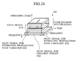
- MMSEC is a method in which sub-carrier weights 824d are determined to minimize a mean square error between a reception signal 7 obtained by multiplying reception signals 7 using spreading codes and combining them over the spreading code duration to despread the same and a transmission signal 6 which has been actually transmitted by the transmitter 4, as shown in Fig. 12D.
- the sub-carrier weights 824d can be calculated in accordance with the condition of propagation paths that change at every moment. This is advantageous in that the condition of propagation paths can be taken into consideration; the SNR of data symbols obtained by combining a reception signal on each sub-carrier can be improved; and spreading codes for the plurality of data channels #1 to #n can be kept orthogonal to each other.
- Specific sub-carrier weight controllers 82 that execute such methods of determining sub-carrier weights include sub-carrier weight controllers 821 to 828 as shown in Figs. 13A to 13G, for example.
- the sub-carrier weight controller 821 comprises a propagation path variation detector 821a and an inverse number calculating unit 821b.
- the propagation path variation detector 821a detects propagation path variation value 9 from a reception signal 7.
- the inverse number calculating unit 821b calculates the inverse numbers of the propagation path variation value 9 detected by the propagation path variation detector 821a and determines the calculated inverse numbers of the propagation path variation value 9 as sub-carrier weights 821c.
- Such a sub-carrier weight controller 821 can determine the sub-carrier weights 821c using ORC.
- the sub-carrier weight controller 822 comprises a propagation path variation detector 822a.
- the propagation path variation detector 822a detects propagation path variation value 9 from a reception signal 7 and determines the detected propagation path variation value 9 as sub-carrier weights 822b as they are.
- Such a sub-carrier weight controller 822 can determine the sub-carrier weights 822b using MRC.
- the sub-carrier weight controller 823 comprises a weight storage unit 823a.
- the weight storage unit 823a stores a weight having a prescribed value.
- the sub-carrier weight controller 823 acquires the weight having a prescribed value from the weight storage unit 823a and determines the weight having a prescribed value as a sub-carrier weight 823b that is equally used for reception signals 7 on all sub-carriers.
- Such a sub-carrier weight controller 823 can determine the sub-carrier weight 823b using EGC.
- a sub-carrier weight controller 824 shown in Fig. 12D comprises an error estimator 824a, a reference symbol storage unit 824b, and a weight calculating unit 824c.
- the reference symbol storage unit 824b stores a reference symbol.
- the reference symbol is a symbol whose amplitude and phase are known to the transmitter 4 and the receiver 5.
- the reference symbol used here is identical to the pilot symbols that the transmitter 4 is to transmit.
- the error estimator 824a acquires pilot symbols 72 after despreading that are included in a reception signal 7 that have been transmitted by the transmitter 4 and actually received by the receiver 5.
- the error estimator 824a acquires the reference symbol from the reference symbol storage unit 824b.
- the error estimator 824a then compares the phases and amplitudes of the pilot symbols 72 and the reference symbol to obtain errors between pilot symbols that have been transmitted by the transmitter 4 and the pilot symbols 72 after despreading that have been actually received and.
- the error estimator 824a assumes that errors between the pilot symbols 72 after despreading thus obtained and the pilot symbols transmitted by the transmitter 4 are errors between the reception signal 7 after despreading and the transmission signal 6.
- the error estimator 824a inputs estimated error values between the reception signal 7 after despreading and the transmission signal 6 to the weight calculating unit 824c.
- the weight calculating unit 824c calculates mean square errors from the estimated error values between the reception signal 7 after despreading and the transmission signal 6 and calculates sub-carrier weight 824d that yields the minimum mean square error.
- the weight calculating unit 824c sets the sub-carrier weights at preset initial values because there is no pilot symbol 72 after despreading required for estimating error.
- Such a sub-carrier weight controller 824 makes it possible to determine sub-carrier weights 824d using MMSEC.
- the use of received pilot symbols 72 and a reference symbol makes it possible to determine optimum sub-carrier weights 824d by obtaining errors between a reception signal 7 after dispreading and a transmission signal 6 taking the condition of the actual propagation paths into consideration.
- a sub-carrier weight controller 825 shown in Fig. 13D comprises an error estimator 825a, a bit string storage unit 825b, a reference symbol generating unit 825c, and a weight calculating unit 825d.
- the bit string storage unit 825b stores a bit string that is a basis of a reference symbol whose amplitude and phase are known to the transmitter 4 and the receiver 5.
- the bit string storage unit 825b stores bit strings that are bases of pilot symbols that the transmitter 4 is to transmit.
- the reference symbol generating unit 825c acquires the bit string from the bit string storage unit 825b and modulates the bit string to generate a reference symbol. That is, the reference symbol generating unit 825c modulates the bit string to generate a reference symbol identical to the pilot symbols to be transmitted by the transmitter 4.
- the error estimator 825a is substantially similar to the error estimator 824a shown in Fig. 12D except that it acquires the reference symbol from the reference symbol generating unit 825c.
- the weight calculating unit 825d is substantially similar to the weight calculating unit 824c shown in Fig. 12D.
- Such a sub-carrier weight controller 825 makes it possible to determine sub-carrier weights 825e using MMSEC.
- the use of received pilot symbols 72 and a reference symbol thus generated makes it possible to determine optimum sub-carrier weights 825e by obtaining errors between a reception signal 7 after despreading and a transmission signal 6 taking the condition of the actual propagation paths into consideration.
- a sub-carrier weight controller 826 shown in Fig. 13E comprises a channel estimator 826a, a noise power estimator 826b, a number of multiplexed codes estimator 826c, and a weight calculating unit 826d.
- the channel estimator 826a, noise power estimator 826b, and the number of multiplexed codes estimator 826c store a symbol that is identical to pilot symbols to be transmitted by the transmitter 4 as a reference symbol.
- the channel estimator 826a, noise power estimator 826b, and the number of multiplexed codes estimator 826c may store a signal that is identical to pilot signals to be transmitted by the transmitter 4 as a reference signal.
- the channel estimator 826a acquires pilot symbols 72 included in a reception signal 7 which has been transmitted by the transmitter 4 and which has actually been received by the receiver 5.
- the channel estimator 826a compares the phases and amplitudes of the acquired pilot symbols 72 and the reference symbol to obtain propagation path variations of the pilot symbols 72.
- the channel estimator 826a performs channel estimation using the propagation path variations of the pilot symbols 72 to obtain channel estimates.
- the channel estimator 826a may obtain a channel estimated value by comparing pilot signals included in the reception signal 7 and a reference signal.
- the noise power estimator 826b acquires the pilot symbols 72 included in the reception signal 7 which has been transmitted by the transmitter 4 and which has been actually received by the receiver 5. The noise power estimator 826b compares the acquired pilot symbols 72 and the reference symbol to obtain variance of the pilot symbols 72. The noise power estimator 826b estimates the noise power per sub-carrier of the reception signal 7 using the obtained variance. The noise power estimator 826b may compare the pilot signals included in the reception signal 7 and the reference signal to obtain variance of the pilot signals.
- the number of multiplexed codes estimator 826c acquires the pilot symbols 72 and data symbols 71 included in the reception signal 7 which has been transmitted by the transmitter 4 and which has been actually received by the receiver 5.
- the number of multiplexed codes estimator 826c calculates the ratio between the power of the pilot symbols 72 and the power of the data symbols 71.
- the number of multiplexed codes estimator 826c estimates the number of multiplexed codes from the calculated ratio between the power of the pilot symbols 72 and the power of the data symbols 71.
- the spreading codes are generated in a quantity corresponding to the number of data channels #1 to #n. Therefore, the number of multiplexed codes corresponds to the number of data channels #1 to #n that are code-division-multiplexed. Therefore, the number of multiplexed codes estimator 826c may estimate the number of multiplexed codes based on the pilot signals and data signals included in the reception signal 7.
- the channel estimator 826a, noise power estimator 826b, and the number of multiplexed codes estimator 826c respectively input a channel estimated value, an estimated value of noise power, and an estimated value of the number of multiplexed codes to the weight calculating unit 826d.
- the weight calculating unit 826d substitutes the channel estimated value, the estimated value of noise power, and the estimated value of the number of multiplexed codes of the reception signal 7 in Equation 1 shown below to calculate sub-carrier weights 826e.
- Equation 1 is an equation for calculating sub-carrier weights 826e that yield a minimum mean square error between a reception signal 7 obtained by multiplying reception signals 7 using spreading codes to despread the same and a transmission signal 6 actually transmitted by the transmitter 4.
- w m represents sub-carrier weight
- h m represents channel estimated value
- N represents noise power
- C mux represents the number of multiplexed codes.
- m represents the number of sub-carriers.
- a method of calculating a sub-carrier weight is described in Design and Performance of Multicarrier CDMA System in Frequency-Selective Rayleigh Fading Channels (S.
- Such a sub-carrier weight controller 824 can obtain sub-carrier weight 826e using MMSEC. Since actually received pilot symbols 72 and data symbols 71 and a reference symbol are used, the sub-carrier weight controller 824 can obtain channel estimated value, noise power, and the number of multiplexed codes taking the actual condition of the propagation paths into consideration, which makes it possible to obtain optimum sub-carrier weight 826e.
- a sub-carrier weight controller 827 shown in Fig. 13F comprises an error estimator 827a, a reference symbol storage unit 827b, and a weight updating unit 827c.
- the error estimator 827a and the reference symbol storage unit 827b are substantially similar to the error estimator 824a and the reference symbol storage unit 824b shown in Fig. 12D.
- the weight updating unit 827c substitutes estimated errors between a reception signal 7 after despreading and a transmission signal 6 in an adaptive algorithm.
- the weight updating unit 827c executes the adaptive algorithm to obtain sub-carrier weight 827d that are gradually updated.
- the adaptive algorithm is an algorithm for gradually updating the sub-carrier weight 827d based on the estimated errors between the reception signal 7 after despreading and the transmission signal 6 such that the mean square errors of the errors is minimized.
- LMS least mean square
- RLS recursive least squares
- adaptive algorithm is described in orthogonal multi-carrier techniques applied to direct sequence CDMA systems (A. Chouly et al., 1993 IEEE Global Telecommunications Conference).
- the weight updating unit 827c sets the sub-carrier weights 827d at preset initial values because there is no despread pilot symbol required for estimating an error.
- a sub-carrier weight controller 824 makes it possible to determine sub-carrier weights 827d using MMSEC.
- the use of received pilot symbols 72 and a reference symbol allows the weight updating unit 827c to determine optimum sub-carrier weights 827d by obtaining errors between a reception signal 7 after despreading and a transmission signal 6 taking the condition of the actual propagation paths into consideration. Further, the weight updating unit 827c can gradually update the sub-carrier weights 827d to minimize mean square errors between the reception signal 7 after despreading and the transmission signal 6 using the adaptive algorithm.
- a sub-carrier weight controller 828 shown in Fig. 13G comprises an error estimator 828a, a bit string storage unit 828b, a reference symbol generating unit 828c, and a weight updating unit 828d.
- the error estimator 828a, bit string storage unit 828b, and reference symbol generating unit 828c are substantially similar to the error estimator 825a, bit string storage unit 825b, and reference symbol generating unit 825c shown in Fig. 13D.
- the weight updating unit 828d is substantially similar to the weight updating unit 827c shown in Fig. 13F.
- Such a sub-carrier weight controller 828 makes it possible to determine sub-carrier weight 828e using MMSEC.
- the use of pilot symbols 72 received by the receiver 5 and a generated reference symbol allows the sub-carrier weight controller 828 to determine optimum sub-carrier weights 828e by obtaining errors between a reception signal 7 after despreading and a transmission signal 6 taking the condition of the actual propagation paths into consideration. Further, the sub-carrier weight controller 828 can gradually update the sub-carrier weight 828e such that a mean square error between the reception signal 7 after despreading and the transmission signal 6 is minimized using the adaptive algorithm.
- the error estimators 824a, 825a, 827a, and 828a shown in Figs. 12D, 13D, 13F, and 13G may obtain errors between pilot symbols 72 and data symbols 71 after despreading, i.e., errors between the reception signal 7 after despreading itself and a reference signal and may assume the errors to be errors between the reception signal 7 after despreading and the transmission signal 6.
- the weight calculating units 824c and 825d and the weight updating units 827c and 828d can use estimated errors between an actually received reception signal 7 after despreading and a transmission signal 6 to obtain more appropriate sub-carrier weights 824d, 825e, 827d, and 828e.
- a determination feedback part is provided to allow the error estimators 824a, 825a, 827a, and 828a to acquire a reference signal.
- the determination feedback part acquires a reception signal 7 combined over the spreading code duration of the spreading codes at the symbol combining unit 55.
- the determination feedback part determines the properties of the transmission signal 6 based on the reception signal 7 and inputs the same to the error estimators 824a, 825a, 827a, and 828a.
- the error estimators 824a, 825a, 827a, and 828a use the transmission signal 6 as determined by the determination feedback part as a reference signal.
- the sub-carrier weight controller 82 may obtain sub-carrier weights by detecting data about a reception signal 7 such as the propagation path variation value 9 of the reception signal 7, the phases and amplitudes of the pilot symbols 72 or pilot signals, and the power of the data symbols 71 or data signals as seen in the case wherein the sub-carrier weight controller 821 using ORC, the sub-carrier weight controller 822 using MRC, or any of the sub-carrier weight controllers 824 to 828 using the MMSEC are used as the sub-carrier weight controller 82.
- Such data about a reception signal 7 required for determining sub-carrier weight is hereinafter referred to as "sub-carrier weight data”.
- the sub-carrier weight data includes the propagation path variation value 9 of the reception signal 7, the phases and amplitudes of the pilot symbols 72 or pilot signals, and the power of the data symbols 71 or data signals itself, and data including the propagation path variation value 9 of the reception signal 7, the phases and amplitudes of the pilot symbols 72 or pilot signals, and the power of the data symbols 71 or data signals after the influence of noises and guard intervals are deleted from the reception signal 7.
- the sub-carrier weight controller 82 of the receiver 5 acquires sub-carrier weight data from a reception signal 7 which has been obtained by combining reception signals 7 multiplied by antenna weights at the antenna signal combining unit 53 among the antennas and which has not yet been multiplied by sub-carrier weights at the sub-carrier weight multiplier 54.
- the sub-carrier weight controller 82 may acquire sub-carrier weight data from the reception signal 7 obtained through combining performed between the plurality of antennas at the antenna signal combining unit 53. Therefore, the sub-carrier weight controller 82 is not required to acquire the sub-carrier weight data from the signal processing units 52 1 to 52n of the plurality of antennas 51 1 to 51n, thus allowing simplified processing.
- the sub-carrier weight controller 82 may acquire sub-carrier weight data from a reception signal 7 which has been multiplied by antenna weight and which has been obtained through combining performed between the plurality of antennas.
- the sub-carrier weight controller 82 can obtain sub-carrier weight in consideration to the influence of the multiplication of the antenna weight on the reception signal 7 and the influence of the combining among the antennas on the reception signal 7.
- the sub-carrier weight controller 82 acquires the sub-carrier weight data from the reception signal 7 which has been multiplied using spreading codes in this case, it can obtain more appropriate sub-carrier weights using data on the reception signal 7 which is free from the influence of the spreading codes multiplied at the transmitter 4.
- the sub-carrier weight controller 82 may acquire sub-carrier weight data from reception signals 7 which have been multiplied by antenna weights at the antenna weight multipliers 52f and which have not been combined among the antennas into a reception signal at the antenna signal combining unit 53 yet.
- the sub-carrier weight controller 82 can acquire sub-carrier weight data from a reception signal 7 that has been multiplied by antenna weight and can therefore obtain sub-carrier weights in consideration of the influence of the multiplication of the antenna weights on the reception signal 7.
- the sub-carrier weight controller 82 may estimate sub-carrier weight data after combining among the antennas based on the sub-carrier weight data acquired from the reception signals 7 which have been multiplied by antenna weights at the antenna weight multipliers 52f and which have not yet been combined among the antennas into a reception signal at the antenna signal combining unit 53.
- the sub-carrier weight controller 82 may obtain sub-carrier weights from the estimated data.
- the sub-carrier weight controller 82 acquires the sub-carrier weight data from the reception signal 7 that has been multiplied using spreading codes, more appropriate sub-carrier weights can be obtained using data on the reception signal 7 that is free from the influence of the spreading codes multiplied at the transmitter 4.
- the sub-carrier weight controller 82 may acquire sub-carrier weight data from reception signals 7 located between the time/frequency converter 52c and the spreading code multipliers 52e or reception signals 7 located between the spreading code multipliers 52e and the antenna weight multipliers 52f.
- the sub-carrier weight controller 82 When any of the sub-carrier weight controllers 824, 825, 827, and 828 shown in Figs. 12D, 13D, 13F, and 13G are used as the sub-carrier weight controller 82, sub-carrier weight must be obtained using pilot symbols 72 after despreading or a reception signal 7 after despreading. Therefore, in those cases, the sub-carrier weight controller 82 preferably acquires sub-carrier weight data from a reception signal 7 that has been despread by the symbol combining units 55. In this case, since the sub-carrier weight controller 82 can use the acquired sub-carrier weight data as it is, the process can be simplified.
- sub-carrier weight data is preferably acquired from a reception signal 7 that is demultiplexed into each sub-carrier as shown in Fig. 9.
- the sub-carrier weight controller 82 preferably determines a sub-carrier weight based on the reception signal 7 on each sub-carrier.
- the channel estimator 826a, noise power estimator 826b, and the number of multiplexed codes estimator 826c can obtain a channel estimated value, an estimated value of noise power, and an estimated value of the number of multiplexed codes for each sub-carrier, respectively.
- the antenna weight controller 81 and the sub-carrier weight controller 82 acquire antenna weight data and sub-carrier weight data, respectively, in different positions as described above, the antenna weight controller 81 and the sub-carrier weight controller 82 can acquire the data in the optimum positions for determining antenna weights and sub-carrier weights respectively, which makes it possible to perform control with high accuracy.
- the weight controller 8 may acquire common data on a reception signal 7 from one location as antenna weight data and sub-carrier data to allow the antenna weight controller 81 and the sub-carrier weight controller 82 to use common data.
- the weight controller 8 can acquire the antenna weight data and sub-carrier weight data at a time.
- the process at the weight controller 8 can be simplified.
- the configuration of the receiver 5 is also simplified.
- the antenna weight multipliers 52f multiply the reception signal 7 of each of the antennas 51 1 to 51n by the antenna weights; the antenna signal combining unit 53 performs antenna diversity combining to combine the reception signals 7 multiplied by antenna weights among the antennas; the sub-carrier weight multipliers 54 thereafter multiply the reception signals 7 which have been multiplied using spreading codes on each of the sub-carriers by the sub-carrier weights; and the symbol combining units 55 perform despreading to combine the reception signals 7 multiplied by the sub-carrier weights over the spreading code duration of the spreading codes.
- the sub-carrier weight controller 82 determines whether to maintain a state of the reception signals 7 multiplied by the antenna weights or to adjust the state of the reception signals multiplied by the antenna weight again, based on the antenna weight by which the reception signals 7 are first multiplied.
- the sub-carrier weight controller 82 preferably adjusts the sub-carrier weights based on a result of determination.
- the antenna weight controller 81 preferably determines the antenna weight by using the EGC method
- the sub-carrier weight controller 82 preferably determines the sub-carrier weight by using either the MMSEC method or the EGC method.
- the transmitter 4 generates a data symbol to be transmitted over each of the data channels #1 to #n (S101).
- the transmitter 4 performs error-correction-encoding on the generated data symbol (S102).
- the transmitter 4 performs a data modulating process on the data symbol that has been subjected to error-correction-encoding (S103).
- the transmitter 4 performs serial/parallel conversion on the data symbol that have been subjected to the data modulating process to divide the data symbol into a plurality of data symbols (S104).
- the transmitter 4 copies the plurality of data symbols obtained through serial/parallel conversion and dividing to provide a copy of the same in a quantity equal to the number of spreading code duration of spreading codes corresponding to the data channels #1 to #n over which the data symbols are transmitted (S105).
- the transmitter 4 generates the spreading code corresponding to each of the data channels that are assigned to the data channel.
- the transmitter 4 then multiplies the copied data symbols using the spreading codes corresponding to the data channels #1 to #n for transmitting the data symbols (S106) to obtain data signals.
- the transmitter 4 inserts pilot signals in the data signals (S107).
- the transmitter 4 combines the data signal and pilot signal in each of the data channels #1 to #n to perform code-division-multiplexing (S108).
- the transmitter 4 spreads the code-division-multiplexed data signals over a plurality of sub-carriers having different frequencies of transmitting data signals (S109).
- the transmitter 4 generates a multi-carrier CDMA signal by performing frequency/time signal conversion on the data signals to assign the data signals to the plurality of sub-carriers having different frequencies.
- the transmitter 4 inserts guard intervals between each of the data signals spread among the plurality of sub-carriers (S110).
- the transmitter 4 transmits the multi-carrier CDMA signal having the guard intervals inserted into the receiver 5 as a transmission signal 6 (S111).
- the plurality of antennas 51 1 to 51n of the receiver 5 receive a multi-carrier CDMA signal which is a signal obtained by multiplying a plurality of data symbols transmitted by the transmitter 4 and transmitted over the plurality of data channels #1 to #n using spreading codes for the respective data channels and which is transmitted by the plurality of sub-carriers having different frequencies (S201).
- the receiver 5 detects symbol timing for each of the reception signals 7 received by the antennas 51 1 to 51n (S202).
- the receiver 5 deletes guard intervals inserted in the reception signals 7 (S203).
- the receiver 5 performs time/frequency conversion on the reception signals 7 to demultiplex the reception signals 7 spread over the plurality of sub-carriers having different frequencies into a reception signal 7 on each of the sub-carriers (S204). Then, the receiver 5 generates spreading codes identical to the spreading codes by which the reception signals 7 have been multiplied. The receiver 5 multiplies the reception signals 7 received by the plurality of antennas 51 1 to 51n using spreading codes for the data channels associated with the reception signals 7 (S205).
- the receiver 5 determines antenna weight and multiplies the reception signal 7 of each of the antennas 51 1 to 51n by an antenna weight thus determined (S206).
- the receiver 5 combines the reception signals 7 among the antennas 51 1 to 51n (S207).
- antenna diversity combining is performed.
- the receiver 5 determines sub-carrier weight and multiplies the reception signal on each of the sub-carriers by a sub-carrier weight thus determined (S208).
- the receiver 5 combines the reception signals 7 over the spreading code duration of the spreading codes (S209). despreading is thus performed.
- data symbols are recovered to their states before the multiplication using spreading codes at the transmitter 4.
- the receiver 5 performs parallel/serial conversion on the data symbols recovered through the combining over the spreading code duration (S210).
- the receiver 5 performs a data demodulating processing on the parallel/serial converted data symbols (S211).
- the receiver 5 performs error-correction-decoding processing on the data symbols that have been subjected to the data demodulating processing (S212).
- the receiver 5 recovers the data symbols that have been subjected to the error-correction-decoding processing to a state in which they can be output to an output apparatus such as a display or speaker and outputs them to the output apparatus (S213).
- the communication system 1, receivers 5 and 205 receive a transmission signals 6 which are signal obtained by multiplying a plurality of data symbols using the spreading codes for each of the data channels #1 to #n and which are transmitted over a plurality of sub-carriers having different frequencies.
- the spreading code generating unit 52d generates spreading codes for the data channels corresponding to resultant reception signals 7.
- the spreading code multipliers 52e multiply the reception signals 7 using the spreading codes.
- the weight controller 8 adjusts antenna weights and sub-carrier weights such that the spreading codes for the plurality of data channels #1 to #n are orthogonal to each other.
- the antenna weight multipliers 52f and the sub-carrier weight multipliers 54 multiply the reception signals 7 by the antenna weights and sub-carrier weights adjusted by the weight controller 8.
- the antenna signal combining unit 53 and symbol combining units 55 combine the reception signals 7 multiplied by the antenna weights and sub-carrier weights among the antennas and over the spreading code duration of the spreading codes.
- the reception signals 7 are thus multiplied by the antenna weights and sub-carrier weights which have been adjusted by the weight controller 8 such that the spreading codes for the plurality of data channels #1 to #n are orthogonal to each other. Therefore, the spreading codes for the data channels #1 to #n by which the reception signals 7 are multiplied are orthogonal to each other. As a result, data symbols obtained by the receiver 5 or 205 are less affected by interference between the data channels #1 to #n caused by the destruction of orthogonality between the spreading codes.
- antenna diversity combining can be appropriately applied in the multi-carrier CDMA transmission method in the receivers 5 and 205. Consequently, a high signal power to noise power ratio can be achieved for the reception signal 7 on each sub-carrier in the receivers 5 and 205, which makes it possible to achieve improved signal transmission characteristics.
- the weight controller 8 comprises the antenna weight controller 81 and the sub-carrier weight controller 82.
- the weight controller 8 adjusts antenna weights and the sub-carrier weights and determines antenna weights and sub-carrier weights separately.
- the receiver 5 comprises the antenna weight multipliers 52f configured to multiply the reception signal 7 at each antenna by an antenna weights, and the sub-carrier weight multipliers 54 configured to multiply the reception signal 7 on each of the sub-carrier by sub-carrier weights. Further, there is provided the antenna signal combining unit 53 configured to combine the reception signals among the antennas and the symbol combining units 55 configured to combine the reception signals 7 over the spreading code duration of the spreading codes.
- the receiver 5 can separately perform a process of determining antenna weights, multiplying the reception signal 7 at each antenna by an antenna weight, and combining the reception signals 7 among the antennas and a process of determining sub-carrier weight, multiplying the reception signal 7 on each sub-carrier by a sub-carrier weight, and combining the reception signals 7 over the spreading code duration of the spreading codes.
- the antenna weight controller 81 can determine antenna weight in consideration to the process of multiplying the reception signals 7 by sub-carrier weight and combining them over the spreading code duration
- the sub-carrier weight controller 82 can determine sub-carrier weight in consideration to the process of multiplying the reception signals 7 by antenna weight and combining them among the antennas 51 1 to 51n.
- the antenna weight multipliers 52f multiply the reception signal 7 at each antenna by the antenna weights and the antenna signal combining unit 53 performs antenna diversity combining by combining the reception signals 7 among the antennas
- the sub-carrier weight multipliers 54 multiply the reception signal 7 on each of the sub-carriers by the sub-carrier weights, the signal 7 having been multiplied using the spreading code.
- the symbol combining units 55 perform despreading by combining the reception signals 7 that have been multiplied by the sub-carrier weights over the spreading code duration of the spreading codes.
- the sub-carrier weight multipliers 54 and the symbol combining units 55 are not required to perform the process of multiplying each of the reception signals 7 at the plurality of antennas 51 1 to 51n by the sub-carrier weight and the process of combining the reception signals 7 over the spreading code duration of the spreading codes separately. That is, the sub-carrier weight multipliers 54 and the symbol combining units 55 can perform the sub-carrier multiplying process and the process of combining the reception signals 7 over the spreading code duration of the spreading codes on a reception signal 7 obtained through combining between the plurality of antennas 51 1 to 51n on a collective basis.
- the communication system of the second embodiment has a receiver 305 as shown in Fig. 16.
- the receiver 305 comprises a plurality of antennas 51 1 to 51n, a plurality of signal processing units 352 1 to 352n, a weight controller 308, an antenna signal symbol combining unit 353, a serial/parallel converter 56, a data demodulator 57, an error-correction-decoder 58, and a data symbol recovering unit 59.
- the signal processing units 352 1 to 352n have a symbol timing detector 52a, a guard interval deleting unit 52b, a time/frequency converter 52c, a spreading code generating unit 52d, a plurality of spreading code multipliers 52e, and a plurality of collective weight multipliers 352f.
- the plurality of antennas 51 1 to 51n, the serial/parallel converter 56, the data demodulator 57, the error-correction-decoder 58, the data symbol recovering unit 59, the symbol timing detector 52a, the guard interval deleting unit 52b, the time/frequency converter 52c, the spreading code generating unit 52d, and the spreading code multipliers 52e are substantially similar to those in the receiver 5 shown in Fig. 8. Therefore, they are indicated by like symbols in Fig. 16 and will not be described here.
- a transmission signal 6 is received by the plurality of antennas 51 1 to 51n, processing similar to that for the receiver 5 shown in Fig. 8 is performed up to the multiplication of reception signals 7 using spreading codes at the spreading code multipliers 52e.
- the spreading code multipliers 52e input the reception signals 7 to the collective weight multipliers 352f after multiplying them using spreading codes.
- the weight controller 308 adjusts antenna weights and sub-carrier weights such that the spreading codes for the plurality of data channels #1 to #n are orthogonal to each other and determines weights by which the reception signal 7 on each sub-carrier at each antenna is to be collectively multiplied (hereinafter referred to as "collective weight").
- the weight controller 308 preferably determines the collective weights by adjusting the antenna weight and sub-carrier weight such that the spreading codes for the plurality of data channels #1 to #n are orthogonal to each other and such that a great SNR is achieved.
- the receiver 305 can obtain a reception signal 7 with a great signal power to noise ratio thus achieving improved signal transmission characteristics.
- the weight controller 308 determines collective weights by adjusting antenna weights using the selective combining method, EGC method, or the MRC etc. and adjusting sub-carrier weights using ORC, MRC, EGC, or MMSEC etc.
- the weight controller 308 comprises the configuration of any of the antenna weight controllers 811 to 813 shown in Figs. 10A, 10B, and 10C and the configuration of any of the sub-carrier weight controllers 821 to 828 shown in Fig. 12D and Figs. 13A to 13G.
- the weight controller 308 directly determines collective weights by adjusting antenna weight and sub-carrier weight.
- a weight controller 408 as shown in Fig. 17 may be used as the weight controller for determining the collective weight.
- the weight controller 408 has an antenna weight controller 481, a sub-carrier weight controller 482, and a collective weight controller 483.
- the antenna weight controller 481 determines antenna weight.
- the sub-carrier weight controller 482 determines sub-carrier weight.
- the antenna weight controller 481 determines antenna weight using the selective combining method, EGC method, or MRC method etc. as described above.
- the antenna weight controllers 811 to 813 shown in Figs. 10A, 10B, and 10C may be used as the antenna weight controller 481.
- the sub-carrier weight controller 482 determines sub-carrier weight using ORC, MRC, EGC, or MMSEC etc. as described above.
- the sub-carrier weight controllers 821 to 828 shown in Fig. 12D and Figs. 13A to 13G may be used as the sub-carrier weight controller 482.
- the collective weight controller 483 adjusts the antenna weight determined by the antenna weight controller 481 and the sub-carrier weight determined by the sub-carrier weight controller 482 to determine collective weight 484.
- the weight controller 408 determines antenna weight and sub-carrier weight separately and then determines the collective weights 484 based on them.
- the collective weight multipliers 352f multiply collectively the reception signal 7 on each of the sub-carrier of each of the antennas 51 1 to 51n by the collective weights adjusted by the weight controller 308 or 408.
- the collective weight multipliers 352f multiply reception signals 7 received by the antennas 51 1 to 51n for processing by the signal processing units 352 1 to 352n by collective weights.
- the collective weight multipliers 352f are provided in a quantity equal to the number of sub-carriers.
- Each of the collective weight multipliers 352f multiply the reception signal 7 on each sub-carrier input from the respective spreading code multiplier 52e by the collective weight.
- the collective weight multiplier 352f of each of the signal processing units 352 1 to 352n inputs the reception signal 7 multiplied by the collective weight to the antenna signal symbol combining unit 353.
- the antenna signal symbol combining unit 353 is a combining unit for collectively combining the reception signal 7 multiplied by the collective weights among the antennas 51 1 to 51n and over the spreading code duration of the spreading codes.
- the antenna signal symbol combining unit 353 collectively combines the reception signals 7 input from the collective weight multiplier 352f of each of the signal processing units 352 1 to 352n among the antennas 51 1 to 51n and over the spreading code duration of the spreading codes for the data channels #1 to #n associated with the reception signals. Thus, diversity combining and despreading is collectively performed.
- the spreading code multipliers 52e multiply the reception signal 7 on each sub-carrier using the spreading codes for the data channels #1 to #n associated with the reception signal 7, and the collective weight multipliers 352f thereafter collectively multiply the reception signal 7 on each sub-carrier of each of the antennas 51 1 to 51n by the collective weight.
- the antenna signal symbol combining unit 353 collectively combines the reception signals 7 among the antennas 51 1 to 51n and over the spreading code duration of the dispreading codes. As a result of combining at the antenna signal symbol combining unit 353, data symbols are recovered to their states before the multiplication of spreading codes at the transmitter.
- a reception signal 7 obtained as a result of combining at the antenna signal symbol combining unit 353 is input to the serial/parallel converter 56. Thereafter, processing similar to in the receiver 5 shown in Fig. 8 is performed to output data symbols.
- the weight controllers 308 and 408 acquire antenna weight data and sub-carrier weight data from reception signals 7 when the selective combining method, maximum ratio combining method, ORC, MRC, or MMSEC is used. As shown in Fig. 16, the weight controllers 308 and 408 collectively acquire antenna weight data and sub-carrier weight data from reception signals 7 which have been multiplied using spreading codes at the spreading code multipliers 52e and which have not yet been multiplied by collective weights at the collective weight multipliers 352f. This simplifies the processing performed by the weight controllers 308 and 408. Further, the weight controllers 308 and 408 may acquire antenna weight data and sub-carrier weight data from reception signals 7 which have been multiplied using spreading codes to eliminate the influence of multiplication of the same using spreading codes at the transmitter. Thus, the weight controllers 308 and 408 can obtain appropriate collective weights.
- the weight controllers 308 and 408 may acquire antenna weight data and sub-carrier weight data from reception signals 7 located between the time/frequency converter 52c and the spreading code multipliers 52e.
- the weight controllers 308 and 408 may acquire antenna weight data and sub-carrier weight data from reception signals 7 from which guard intervals have been deleted by the guard interval deleting units 52b and which have not yet been subjected to time/frequency conversion at the time/frequency converter 52c.
- weight controllers 308 and 408 to acquire antenna weight data and sub-carrier weight data from a single reception signal 7 of each of the antennas 51 1 to 51n before the signal is demultiplexed into a reception signal 7 on each sub-carrier by the time/frequency converter 52c, and the processes performed by the weight controllers 308 and 408 are thereby simplified.
- the weight controllers 308 and 408 may adjust sub-carrier weights to determine collective weights using pilot symbols 72 after despreading or a reception signal 7 after despreading as done by the sub-carrier weight controllers 824, 825, 827, and 828 shown in Figs. 12D, 13D, 13F, and 13G.
- the weight controllers 308 and 408 preferably acquire sub-carrier weight data from a reception signal 7 that has been despread by the antenna signal symbol combining unit 353. This makes it possible to simplify the process at the sub-carrier weight controller 82 because the acquired sub-carrier weight data can be used as it is.
- the weight controllers 308 and 408 may adjust sub-carrier weights to determine collective weights as done by the sub-carrier weight controller 826 shown in Fig. 13E.
- the weight controllers 308 and 408 preferably acquire sub-carrier weight data from a reception signal 7 which has been demultiplexed on a sub-carrier-by-sub-carrier bases. This allows the channel estimator 826a, the noise power estimator 826b, and the number of multiplexed codes estimator 826c to respectively obtain a channel estimate value, an estimated value of noise power, and an estimated value of the number of multiplexed codes for each sub-carrier.
- the weight controllers 308 and 408 may acquire antenna weight data and sub-carrier weight data from different positions. This allows the weight controllers 308 and 408 to acquire data for determining antenna weights and sub-carrier weights in optimum positions, which allows highly accurate control.
- Steps S301 to S305 are substantially similar to steps S201 to S205 shown in Fig. 15.
- the receiver 305 determines collective weight and collectively multiplies a reception signal 7 on each sub-carrier of each of the antennas 51 1 to 51n by a collective weight thus determined (S306).
- the receiver 305 collectively combines the reception signals 7 multiplied by the collective weight among the antennas 51 1 to 51n and over the spreading code duration of spreading codes (S307).
- antenna diversity combining and despreading is performed on a collective basis.
- data symbols are recovered to their states before being multiplied using spreading codes at the transmitter.
- the receiver 305 performs steps S308 to S311 as shown in Fig. 18. Steps S308 to S311 are substantially similar to steps S210 to S213 shown in Fig. 15.
- the weight controller 308 adjusts antenna weight and sub-carrier weight such that the spreading codes for the plurality of data channels #1 to #n are orthogonal to each other and determines the collective weight by which the reception signals 7 are to be collectively multiplied.
- the collective weight multipliers 352f multiply the reception signal 7 on each of the sub-carriers of each of the antennas 51 1 to 51n by the collective weight.
- the antenna signal symbol combining unit 353 collectively combines the reception signals 7 multiplied by the collective weights among the antennas 51 1 to 51n and over the spreading code duration of the spreading codes.
- the reception signals 7 are multiplied by the collective weight which have been adjusted such that the spreading codes for the plurality of data channels #1 to #n are orthogonal to each other at the weight controller 308.
- the spreading codes for the respective data channels #1 to #n by which the reception signals 7 are multiplied are orthogonal to each other.
- data symbols obtained by the receiver 305 are less affected by interference between the data channels #1 to #n caused by the destruction of orthogonality between the spreading codes.
- antenna diversity combining can be thus appropriately applied in the multi-carrier CDMA transmission method.
- a great signal power to noise power ratio can be achieved for a reception signal 7 on each sub-carrier in the receiver 305,thus providing improved signal transmission characteristics.
- the receiver 305 can collectively perform the process of determining collective weights, the process of performing multiplication by the collective weights, and the process of combing reception signals. This allows the processing performed by the receiver 305 to be simplified.
- the configuration of the receiver 305 can also kept simple.
- the communication system of the third embodiment has a receiver 505 as shown in Fig. 19.
- the receiver 505 comprises a plurality of antennas 51 1 to 51n, a plurality of signal processing units 552 1 to 552n, a weight controller 508, a plurality of antenna weight multipliers 553, an antenna signal combining unit 554, a serial/parallel converter 56, a data demodulator 57, an error-correction-decoder 58, and a data symbol recovering unit 59.
- the signal processing units 552 1 to 552n have a symbol timing detector 52a, a guard interval deleting unit 52b, a time/frequency converter 52c, a spreading code generating unit 52d, a plurality of spreading codes multipliers 52e, a plurality of sub-carrier weight multipliers 552f, and a plurality of symbol combining units 552g.
- the plurality of antennas 51 1 to 51n, the serial/parallel converter 56, the data demodulator 57, the error-correction-decoder 58, the data symbol recovering unit 59, the symbol timing detector 52a, the guard interval deleting unit 52b, the time/frequency converter 52c, the spreading code generating unit 52d, and the spreading code multipliers 52e are substantially similar to those in the receiver 5 shown in Fig. 8. Therefore, they are indicated by like symbols in Fig. 19 and will not be described here.
- a transmission signal 6 is received by the plurality of antennas 51 1 to 51n, processing similar to that for the receiver 5 shown in Fig. 8 is performed up to the multiplication of reception signals 7 using spreading codes at the spreading code multipliers 52e.
- the spreading code multipliers 52e input the reception signals 7 to the sub-carrier weight multipliers 552f after multiplying them using spreading codes.
- the weight controller 508 comprises an antenna weight controller 581 and a sub-carrier weight controller 582.
- the weight controller 508 adjusts antenna weight and sub-carrier weight such that the spreading codes for the plurality of data channels #1 to #n are orthogonal to each other.
- the weight controller 508 preferably adjusts antenna weight and sub-carrier weight such that the spreading codes for the plurality of data channels #1 to #n are orthogonal to each other and such that a great signal power to noise power ratio is achieved.
- the weight controller 508 adjusts antenna weight and sub-carrier weight and determines antenna weight and sub-carrier weight separately.
- the antenna weight controller 581 determines antenna weight using the selective combining method, EGC method, or MRC method etc.
- the antenna weight controllers 811 to 813 shown in Figs. 10A, 10B, and 10C may be used as the antenna weight controller 581.
- the sub-carrier weight controller 582 determines sub-carrier weight using ORC, MRC, EGC, or MMSEC etc.
- the sub-carrier weight controllers 821 to 828 shown in Fig. 12D and Figs. 13A to 13G may be used as the sub-carrier weight controller 582.
- the sub-carrier weight multipliers 552f of the respective signal processing units 552 1 to 552n multiply reception signals 7 on respective sub-carriers received by the antennas 51 1 to 51n to be processed by the signal processing units 552 1 to 552n by sub-carrier weights.
- the sub-carrier weight multipliers 552f are provided in a quantity equal to the number of sub-carriers.
- the respective sub-carrier weight multipliers 552f multiply the reception signals 7 on the respective sub-carriers input from the respective spreading code multipliers 52e by the sub-carrier weights.
- Each of the sub-carrier weight multipliers 552f inputs the reception signal 7 on the respective sub-carriers multiplied by the sub-carrier weight to the symbol combining units 552g.
- the symbol combining units 552g of the respective signal processing units 552 1 to 552n combine the reception signals 7 on the respective sub-carriers received by the antennas 51 1 to 51n to be processed by the signal processing units 552 1 to 552n over the spreading code duration of the spreading codes for the data channels #1 to #n associated with the reception signals 7.
- the symbol combining units 552g combine the reception signals 7 on the respective sub-carriers multiplied by the sub-carrier weights and input from the sub-carrier weight multipliers 552f over the spreading code duration. Despreading is thus performed.
- the symbol combining units 552g input a reception signal 7 obtained through the combining to antenna weight multipliers 553.
- the antenna weight multipliers 553 multiply the reception signals 7 after despreading input from the symbol combining units 552g of the respective signal processing units 552 1 to 552n by antenna weights.
- the antenna weight multipliers 553 are provided in a quantity equal to the number of symbol combining units 552g of all of signal processing units 552 1 to 552n.
- the respective antenna weight multipliers 553 input the reception signals 7 multiplied by the antenna weights to the antenna signal combining unit 554.
- the antenna signal combining unit 554 combines the reception signals 7 input from the antenna weight multipliers 553 among the antennas 51 1 to 51n. Antenna diversity combining is thus performed.
- the spreading code multipliers 52e multiply the reception signals 7 on the respective sub-carriers using the spreading codes
- the sub-carrier weight multipliers 552f multiply the reception signals 7 on the respective sub-carriers by sub-carrier weights.
- the symbol combining units 552g combine the reception signals 7 multiplied by the sub-carrier weights over the spreading code duration of the spreading codes to despread the same. Data symbols are recovered to their states before multiplication using spreading codes at the transmitter 4.
- the antenna weight multipliers 553 multiply the reception signals 7 at the respective antennas 51 1 to 51n, which have been combined over the spreading code duration by the antenna weights.
- the antenna signal combining unit 554 performs antenna diversity combining to combine the reception signals 7 which have been multiplied by the antenna weights after being despread among the antennas 51 1 to 51n.
- the reception signal 7 combined by the antenna signal combining unit 554 is input to the serial/parallel converter 56. Thereafter, processing similar to that for the receiver 5 shown in Fig. 8 is performed to output data symbols.
- the sub-carrier weight multipliers 552f multiply the reception signals 7 which have been multiplied using the spreading codes on each of the sub-carriers by the sub-carrier weights; the symbol combining units 552g performs despreading to combine the reception signals 7 multiplied by the sub-carrier weights over the spreading code duration of the spreading codes; the antenna weight multipliers 553 thereafter multiply the reception signals 7 of each of the antennas 51 1 to 51n by the antenna weights ; and the antenna signal combining unit 554 performs antenna diversity combining to combine the reception signals 7 among the antennas.
- the antenna weight controller 581 determines to whether maintain a state of the reception signals multiplied by the sub-carrier weights or to adjust the state of the reception signals again, based on the sub-carrier weights by which the reception signals 7 are first multiplied.
- the antenna weight controller 581 preferably adjusts the antenna weights based on a result of determination.
- the sub-carrier weight controller 582 preferably determines the sub-carrier weights by using the MMSEC method, and the antenna weight controller 581 preferably determines the antenna weights by using the EGC method.
- the weight controller 508 acquires antenna weight data and sub-carrier weight data form reception signals 7 when the selective combining method, maximum ratio combining method, ORC, MRC, or MMSEC is used. As shown in Fig. 19, the antenna weight controller 581 acquires antenna weight data from reception signal 7 at each antenna that has been combined over the spreading code duration by the symbol combining units 552g. The antenna weight controller 581 determines the antenna weight based on the reception signal 7 at each antenna, which has been combined by the symbol combining units 552g over the spreading code duration. Thus, the antenna weight controller 581 can determine the antenna weights in consideration to the influence of interference between the data channels on the reception signal 7 which has actually been multiplied by the sub-carrier weights and combined over the spreading code duration. This makes it possible to reduce the influence of interference between the data channels on data symbols more appropriately and to achieve higher transmission characteristics.
- the antenna weight controller 581 may acquire antenna weight data from reception signals 7 which have been multiplied by sub-carrier weights by the sub-carrier weight multipliers 552f and which have not yet been combined by the symbol combining units 552g. This eliminates the influence of multiplication using spreading codes at the transmitter and makes it possible to determine antenna weights based on antenna weight data after the multiplication by the sub-carrier weights. Therefore, the antenna weight controller 582 can determine the antenna weights in consideration for the influence of multiplication of the reception signals 7 by the sub-carrier weights, and more appropriate antenna weights can be obtained because reception signals 7 free from the influence of multiplication using spreading codes are used.
- the antenna weight controller 581 may acquire antenna weight data from reception signals 7 which have been multiplied using spreading codes at the spreading code multipliers 52e and which have not yet been multiplied by sub-carrier weights at the sub-carrier weight multipliers 552f, reception signals 7 from which guard intervals have been deleted by the guard interval deleting units 52b and which have not yet been subjected to a time/frequency conversion process at the time/frequency converters 52c, or reception signals 7 which have been demultiplexed into reception signals 7 on the respective sub-carriers by the time/frequency converters 52c and which have not yet been multiplied using spreading codes at the spreading code multipliers 52e.
- the sub-carrier weight controller 582 acquires sub-carrier weight data from reception signals 7 which have been multiplied using spreading codes at the spreading code multipliers 52e and which have not been multiplied by sub-carrier weights at the sub-carrier weight multipliers 552f.
- the sub-carrier weight controller 582 can determine more appropriate antenna weights based on sub-carrier data acquired from the reception signals 7 from which the influence of multiplication using spreading codes at the transmitter 4 has been eliminated.
- the sub-carrier weight controller 582 may acquire sub-carrier eight data between the time/frequency converters 52c and the spreading code multipliers 52e.
- sub-carrier weight controller 582 When any of the sub-carrier weight controller 824, 825, 827, and 828 shown in Figs. 12D, 13D, 13F, and 13G are used as the sub-carrier weight controller 582, sub-carrier weight data is acquired from reception signals 7 which have been despread by the symbol combining units 552g.
- the processing at the sub-carrier weight controller 582 can be simplified because it can use the acquired sub-carrier data as it is.
- sub-carrier weight data is preferably acquired from reception signals 7 which have been demultiplexed on a sub-carrier-by-sub-carrier basis.
- the sub-carrier weight controller 582 then preferably determines sub-carrier weights based on the reception signal 7 on each sub-carrier.
- the channel estimator 826a, noise power estimator 826b, and the number of multiplexed codes estimator 826c can obtain a channel estimate, an estimated value of noise power, and an estimated value of the number of multiplexed codes , respectively, on a sub-carrier-by-sub-carrier basis.
- Steps S401 to S405 are substantially similar to steps S201 to S205 shown in Fig. 15.
- the receiver 505 determines sub-carrier weights and multiplies a reception signal 7 on each sub-carrier received by the antennas 51 1 to 51n by a sub-carrier weight thus determined (S406). Then, the receiver 505 combines the reception signals 7 over the spreading code duration of spreading codes (S407). despreading is thus performed. Thus, data symbols are recovered to their states from before multiplication using the spreading codes at the transmitter.
- the receiver 505 determines antenna weights and multiplies the reception signal 7 of each of the antennas 51 1 to 51n by an antenna weight thus determined. Then, the receiver 505 combines the reception signals 7 among the antennas 51 1 to 51n. Thus, antenna diversity combining is performed (S409).
- the receiver 505 performs steps S410 to S413 as shown in Fig. 20. The steps S410 to S413 are substantially similar to steps S210 to S213 shown in Fig. 15.
- Such a communication system, receiver 505, and method of communication can provide advantages substantially similar to those achieved by the communication system 1, receiver 5, and method of communication shown in Figs. 2, 8, and 15.
- the antenna weight multipliers 553 multiply the reception signals 7 of each of the antennas 51 1 to 51n by the antenna weights after the spreading code multipliers 52e multiply the reception signals 7 using the spreading codes for the data channels #1 to #n corresponding to the reception signals 7;
- the sub-carrier weight multipliers 552f multiply the reception signals 7 on each of the sub-carriers by sub-carrier weights;
- the symbol combining units 552g performs despreading by combining the reception signals 7 multiplied by the sub-carrier weights over the spreading code duration of the spreading codes.
- the antenna signal combining unit 554 performs antenna diversity combining by combining the reception signals 7 multiplied by the antenna weights among the antennas after the dispreading is performed.
- the antenna weight controller 581 can determine antenna weights in consideration of the influence of interference between the data channels on the reception signals 7 which have been multiplied using the spreading codes, multiplied by the sub-carrier weights, and combined over the spreading code duration of the spreading codes, i.e., the reception signals 7 which have been despread. Then, the antenna weight multipliers 553 multiply the signals by the antenna weights. Finally, the antenna signal combining unit 554 combines the reception signals 7 which have been multiplied by the antenna weights determined in consideration of the influence of interference between the data channels #1 to #n among the antennas.
- the receiver 505 can adequately reduce the influence of interference between the data channels on data symbols, thus achieving improved signal transmission characteristics.
- the communication system of the fourth embodiment has a receiver 605 as shown in Fig. 21.
- the receiver 605 has a plurality of antennas 51 1 to 51n, a plurality of signal processing units 652 1 to 652n, a weight controller 608, antenna signal combining unit 653, a time/frequency converter 654, a spreading code generating unit 655, a plurality of spreading code multipliers 656, a plurality of sub-carrier weight multipliers 657, a plurality of symbol combining units 658, a serial/parallel converter 56, a data demodulator 57, an error-correction-decoder 58, and a data symbol recovering unit 59.
- the signal processing units 652 1 to 652n have a symbol timing detector 52a, a guard interval deleting unit 52b, and an antenna weight multiplier 652c.
- the plurality of antennas 51 1 to 51n, the serial/parallel converter 56, the data demodulator 57, the error-correction-decoder 58, the data symbol recovering unit 59, the symbol timing detector 52a, and the guard interval deleting unit 52b are substantially similar to those of the receiver 5 shown in Fig. 8. Therefore, they are indicated by like reference numerals in Fig. 21 and will not be described here.
- the weight controller 608 has an antenna weight controller 681 and a sub-carrier weight controller 682.
- the weight controller 508 adjusts antenna weights and sub-carrier weights such that the spreading codes for the plurality of data channels #1 to #n are orthogonal to each other.
- the weight controller 608 preferably adjusts antenna weights and sub-carrier weights such that the spreading codes for the plurality of data channels #1 to #n are orthogonal to each other and such that a great SNR is achieved.
- the weight controller 608 adjusts antenna weights and sub-carrier weights and determines antenna weights and sub-carrier weights separately.
- the antenna weight controller 681 determines antenna weights using the selective combining method, the EGC method, or the maximum ratio combining method.
- the antenna weight controllers 811 to 813 shown in Figs. 10A, 10B, and 10C may be used as the antenna weight controller 681.
- the sub-carrier weight controller 682 determines sub-carrier weights using ORC, MRC, EGC, or MMSEC.
- the sub-carrier weight controllers 821 to 828 shown in Fig. 12D and Figs. 13A to 13G may be used as the sub-carrier weight controller 682.
- the antenna weight controller 681 inputs antenna weights to the antenna weight multipliers 652c of the respective signal processing units 652 1 to 652n.
- the sub-carrier weight controller 682 inputs sub-carrier weights to the sub-carrier weight multipliers 657.
- the antenna weight multipliers 652c of each of the signal processing units 652 1 to 652n multiply reception signals 7 received by the antennas to be processed by the signal processing units 652 1 to 652n by the sub-carrier weights.
- the sub-carrier weight multiplier 652c of each of the antenna signal processing units 652 1 to 652n is required only to multiply one reception signal 7 received by the respective one of the antennas 51 1 to 51n by the antenna weight. Therefore, it is necessary to provide only one such unit in each of the signal processing units 652 1 to 652n.
- the configuration of the signal processing units 652 1 to 652n is thus simplified.
- the antenna weight multiplier 652c of each of the signal processing units 652 1 to 652n inputs the reception signal 7 multiplied by the antenna weight to the antenna signal combining unit 653.
- the antenna signal combining unit 653 combines the reception signals 7 input from the antenna weight multipliers 652c of each of the signal processing units 652 1 to 652n among the antennas 51 1 to 51n. Antenna diversity combining is thus performed.
- the antenna signal combining unit 653 inputs the reception signals 7 combined among the antennas 51 1 to 51n to the time/frequency converter 654.
- the time/frequency converter 654 performs time/frequency conversion on the reception signals 7 after combining among the antennas 51 1 to 51n input from the antenna signal combining unit 653 to demultiplex them into a reception signal 7 on each of the sub-carriers.
- the time/frequency converter 654 inputs the reception signals 7 demultiplexed on a sub-carrier-by-sub-carrier basis to the spreading code multipliers 656.
- the spreading code generating unit 655 generates spreading codes similar to the spreading codes by which the reception signals have been multiplied.
- the spreading code generating unit 655 inputs the generated spreading codes to the spreading code multipliers 656.
- the spreading code multipliers 656 multiply the reception signal 7 on each sub-carrier after the combining among the antennas 51 1 to 51n which has been demultiplexed by the time/frequency converter 654 using the spreading codes of the data channels #1 to #n over which the reception signal 7 has been transmitted in the direction of the frequency axis. By thus multiplying the reception signal 7 using the spreading codes, the influence of the multiplication using the spreading codes at the transmitter is eliminated from the signal.
- the spreading code multipliers 656 are provided in a quantity equal to the number of the sub-carriers.
- Each of the spreading code multipliers 656 multiplies the reception signal 7 on the respective sub-carrier after the combining among the antennas 51 1 to 51n by a spreading code.
- the spreading code multipliers 656 inputs the reception signals 7 multiplied using the spreading codes to the sub-carrier weight multipliers 657.
- the sub-carrier weight multiplier 657 multiplies the reception signal 7 on each sub-carrier input from the respective spreading code multipliers 52e by a sub-carrier weight.
- the sub-carrier weight multipliers 657 are provided in a quantity equal to the number of sub-carriers.
- Each of the sub-carrier weight multipliers 657 inputs the reception signal 7 on each sub-carrier multiplied by the sub-carrier weight to the symbol combining units 658.
- the symbol combining units 658 combine the reception signal 7 on each sub-carrier after the combining among the antennas input from the sub-carrier weight multiplier 657 over the spreading code duration of the spreading codes for the data channels #1 to #n associated with the reception signal 7. Despreading is thus performed.
- the antenna weight multipliers 652c of the respective signal processing units 652 1 to 652n multiply the reception signals 7 by the antenna weights, and the antenna signal combining unit 653 combines them among the antennas 51 1 to 51n.
- the time/frequency converter 654 demultiplex the reception signals 7 after the combining among the antennas into a reception signal on each sub-carrier.
- the spreading code multipliers 656 multiply the reception signal 7 on each sub-carrier after the combining among the antennas 51 1 to 51n using the spreading codes.
- the sub-carrier weight multipliers 657 multiply the reception signals 7 on the respective sub-carriers after the combining among the antennas 51 1 to 51n by the sub-carrier weights, and the symbol combining units 658 combine them over the spreading code duration of the spreading codes. despreading is thus performed. As a result of the combining at the symbol combining units 658, data symbols are recovered to their states before the multiplication using spreading codes at the transmitter.
- the reception signal 7 combined by the symbol combining units 658 is input to the serial/parallel converter 56. Thereafter, processes similar to those in the receiver 5 shown in Fig. 8 are performed to output data symbols.
- the antenna weight multipliers 652c multiply the reception signals 7 of each of the antennas 51 1 to 51n by the antenna weights; the antenna signal combining units 653 perform antenna diversity combining to combine the reception signals 7 multiplied by the antenna weights among the antennas; the sub-carrier weight multipliers 657 thereafter multiply the reception signals 7 which have been multiplied by the spreading codes on each of the sub-carriers by the sub-carrier weights; and the symbol combining units 658 perform despreading to combine the reception signals 7 multiplied by the sub-carrier weights over the spreading code duration of the spreading codes.
- the sub-carrier weight controller 682 determines to whether maintain the state of the reception signals 7 multiplied by the antenna weights or to adjust the state of the reception signals multiplied by the antenna weights again, based on the antenna weights by which the reception signals 7 are first multiplied.
- the sub-carrier weight controller 682 preferably adjusts the sub-carrier weights based on a result of determination.
- the antenna weight controller 681 preferably determines the antenna weights by using the EGC method
- the sub-carrier weight controller 682 preferably determines the sub-carrier weights by using either the MMSEC method or EGC method.
- the weight controller 608 acquires antenna weight data and sub-carrier weight data from reception signals 7 when the selective combining method, maximum ratio combining method, ORC, MRC, or MMSEC is used. As shown in Fig. 21, the antenna weight controller 681 acquires antenna weight data from a reception signal 7 from which guard intervals have been deleted by the guard interval deleting unit 52b and which has not been multiplied by an antenna weight at the antenna weight multiplier 652c yet.
- the sub-carrier weight controller 682 determines sub-carrier weights based on reception signals 7 which have been combined among the antennas 51 1 to 51n at the antenna signal combining unit 653, demultiplexed into a reception signal on each sub-carrier at the time/frequency converter 654, and multiplied using spreading codes at the spreading code multipliers 656 and which have not been multiplied by sub-carrier weights at the sub-carrier weight multipliers 657 yet.
- the sub-carrier weight controller 682 can determine the sub-carrier weights in consideration to the influence of the multiplication of the reception signals 7 by the antenna weights and combining of them among the antennas 51 1 to 51n.
- the sub-carrier weight controller 682 can use sub-carrier weight data acquired from reception signals 7 from which the influence of the multiplication using spreading codes at the transmitter has been eliminated. Therefore, more appropriate sub-carrier weights can be obtained.
- the sub-carrier weight controller 682 may acquire sub-carrier weight data from reception signals 7 which have been demultiplexed into a reception signal on each sub-carrier at the time/frequency converter 654 and which have not been multiplied using spreading codes at the spreading code multipliers 656 yet.
- sub-carrier weight controller 682 When any of the sub-carrier weight controllers 824, 825, 827, and 828 shown in Figs. 12D, 13D, 13F, and 13G are used as the sub-carrier weight controller 682, sub-carrier weight data is acquired from reception signals 7 which have been despread by the symbol combining units 658. This makes it possible to simplify the process at the sub-carrier weight controller 682 because it can use sub-carrier weight data thus acquired as it is.
- sub-carrier weight data is preferably acquired from reception signals 7 demultiplexed on a sub-carrier-by-sub-carrier basis.
- the sub-carrier weight controller 682 preferably determines a sub-carrier weight based on the reception signal 7 on each sub-carrier. This allows the channel estimator 826a, the noise power estimator 826b, and the number of multiplexed codes estimator 826c can obtain a channel estimate, an estimated value of noise power, and an estimated value of the number of multiplexed codes respectively for each sub-carrier.
- the time/frequency converter 654 may be provided downstream of the antenna weight multiplier 652c in each of the signal processing units 652 1 to 652n.
- the time/frequency converters of the respective signal processing units 652 1 to 652n input reception signals 7 demultilexed on a sub-carrier-by-sub-carrier basis to the antenna signal combining unit 653.
- an antenna weight multiplier 652c is only required to multiply one reception signal 7 received by the respective one of the antennas 51 1 to 51n, and it is required to provide only one such unit in each of the signal processing units 652 1 to 652n. This allows the configuration of the signal processing units 652 1 to 652n to be simplified.
- Steps S501 to S503 are substantially similar to steps S201 to S203 shown in Fig. 15.
- the receiver 605 determines antenna weights and multiplies a reception signal 7 of each of the antennas 51 1 to 51n by the antenna weight thus determined (S504). Then, the receiver 605 combines the reception signals 7 among the antennas 51 1 to 51n (S505). Antenna diversity combining is thus performed. Next, the receiver 605 performs time/frequency conversion on the reception signals 7 to demultiplex the reception signals 7 spread among a plurality of sub-carriers having different frequencies into reception signals on a sub-carrier-by-sub-carrier basis (S506). The receiver 605 generates spreading codes similar to the spreading codes by which the reception signals 7 have been multiplied. Then, the receiver 605 multiplies the reception signals 7 received by the plurality of antennas 511 to 51n using the spreading codes for the data channels associated with the reception signals 7 (S507).
- the receiver 605 determines sub-carrier weights and multiplies the reception signal on each sub-carrier by the determined sub-carrier weights (S508). The receiver 605 then combines the reception signals 7 over the spreading code duration of the spreading codes (S509). despreading is thus performed. Data symbols are thus recovered to their states before the multiplication of the spreading codes at the transmitter.
- the receiver 605 performs steps S510 to S513 as shown in Fig. 22. Steps S510 to S513 are substantially similar to steps S210 to S213 shown in Fig. 15.
- Such a communication system, receiver 605, and method of communication can provide advantages substantially similar to those achieved by the communication system 1, receiver 5, and method of communication shown in Figs. 2, 8, and 15.
- the antenna weight multipliers 652c multiply the reception signals 7 of each of the antennas 51 1 to 51n by antenna weight before the reception signals 7 are demultiplexed by the time/frequency converters 654 into a reception signal on each of the sub-carriers
- the antenna signal combining unit 653 combines the reception signals 7 multiplied by the antenna weight among the antennas 51 1 to 51n. Thereafter, the time/frequency converter 654 demultiplexes them into the reception signal on each of the sub-carriers.
- the sub-carrier weight multipliers 657 multiply the reception signals 7 on the respective sub-carriers by sub-carrier weights.
- the symbol combining units 658 combine the reception signals 7 multiplied by the sub-carrier weights over the spreading code duration of spreading codes.
- the time/frequency converter 654, the sub-carrier weight multipliers 657, and the symbol combining units 658 are not required to perform the process of demultiplexing reception signals 7 into a reception signal 7 on each sub-carrier, the process of multiplying them by sub-carrier weights, and the process of combining the reception signals 7 over the spreading code duration of the spreading codes separately on each of signals received by the plurality of antennas 51 1 to 51n.
- the time/frequency converter 654, the sub-carrier weight multipliers 657, and the symbol combining units 658 can perform the process of demultiplexing reception signals 7 into a reception signal 7 on each sub-carrier, the process of multiplying them by sub-carrier weights, and the process of combining the reception signals 7 over the spreading code duration of the spreading codes on a reception signal 7 obtained through combining between the plurality of antennas 51 1 to 51n collectively.
- the communication according to the fifth embodiment of the invention has a transmitter 404 as shown in Fig. 23 or a transmitter 504 as shown in Fig. 25.
- the transmitter 404 has a plurality of signal processing units 441 1 to 441n, a signal combining unit 442, a frequency/time converter 43, a guard interval inserting unit 44, and an antenna 45.
- the signal processing units 441 1 to 441n have a data symbol generating unit 41a, an error-correction-encoder 41b, a data modulator 41c, a serial/parallel converter 241d, a spreading code generating unit 41e, a plurality of symbol copiers 241f, a plurality of spreading code multipliers 241g, a propagation path variation estimating pilot symbol inserting unit 441h, a weight updating pilot signal inserting unit 441i, and a data channel signal combining unit 441j.
- the data symbol generating units 41e, the error-correction-encoders 41b, the data modulators 41c, the spreading code generating units 41e, the frequency/time converter 43, and the guard interval inserting unit 44 are substantially similar to those in the transmitter 4 shown in Fig. 3.
- the serial/parallel converters 241d, the plurality of symbol copiers 241f and the plurality of spreading code multipliers 241g are substantially similar to those in the transmitter 204 shown in Fig. 5. Therefore, description on them is omitted in Fig. 23.
- Propagation path variation estimating pilot symbol inserting unit 441h inserts pilot symbols for estimating a propagation path variation into the data symbols.
- a transmission signal 6 is generated in which a data signal and a pilot signal for estimating propagation path variations are multiplexed.
- Symbols whose amplitude and phase are known to a receiver 5 are used as the pilot symbols for estimating a propagation path variation.
- the pilot symbols for estimating propagation path variation are used by the receiver for estimating a propagation path variation of the reception signal.
- the weight updating pilot signal inserting unit 441i inserts pilot signals for updating weight into the data signals.
- a transmission signal 6 is generated in which a data signal and a pilot signal for updating weights are multiplexed. Symbols whose amplitude and phase are known to the receiver 5 are used as the pilot symbols for updating weights.
- the pilot signals for updating weights are used by the receiver for estimating errors between a reception signal after despreading and a transmission signal to update sub-carrier weights.
- Common pilot symbols may be used in the plurality of data channels #1 to #n as the pilot symbols for estimating propagation path variations and the pilot symbols for updating weights, and different pilot symbols may alternatively be used in each of the data channels #1 to #n.
- the data channel signal combining units 441j combine a data signal, a pilot signal for estimating propagation path variation and a pilot signals for updating weight in each of the data channels #1 to #n.
- the pilot signal for updating weight and the data signal are multiplexed using code-division multiplexing in which they are multiplexed in the direction of a spreading code axis.
- the pilot signal for updating weights and data signal which have been code-division-multiplexed are multiplexed with the pilot signal for estimating propagation path variation using time-division-multiplexing in which they are multiplexed in the direction of a time axis.
- the data symbol generating units 41a through data modulators 41c perform processes similar to those in the transmitter 4 shown in Fig. 3.
- the data modulators 41c and the propagation path variation estimating pilot symbol inserting unit 441h inputs data symbols and pilot symbols for estimating propagation path variation to the serial/parallel converters 241d at different times.
- the data symbols and the pilot symbols for estimating propagation path variations are time-division-multiplexed.
- the data symbols and the pilot symbols for estimating propagation path variations are input to the serial/parallel converters 241d at different times by switching units that switch the input of data symbols from the data modulators 41c to the serial/parallel converters 241d and the input of pilot symbols for estimating propagation path variations from propagation path variation estimating pilot symbol inserting unit 441h to the serial/parallel converters 241d.
- the serial/parallel converters 241d through spreading code multipliers 241g perform processes similar to those in the receiver 204 shown in Fig. 5 except that the spreading code multipliers 241g multiply the pilot symbols for estimating path variations and the data symbols by different spreading codes.
- the spreading code multipliers 241g input data signals and pilot signals for estimating propagation path variations which have been multiplied using spreading codes and which have been time-division-multiplexed to the data channel signal combining units 441j.
- the data channel signal combining units 441j combine the data signals and the pilot signals for estimating propagation path variation to be transmitted over the respective data channels #1 to #n.
- the data channel signal combining units 441j input the combined data signals and pilot signals for estimating propagation path variation to the signal combining unit 442.
- the weight updating pilot signal inserting unit 441i inputs pilot signals for updating weights to the signal combining unit 442, the signals being obtained by multiplying the pilot symbols for updating weights by the same spreading codes as those multiplied on the pilot symbols for estimating a propagation path variation at the signal processing units 441 1 to 441n.
- the signal combining unit 442 multiplex the time-division-multiplexed data signals and pilot signals for estimating propagation path variations input from the data channel signal combining units 441j of the signal processing units 441 1 to 441n of the respective data channels #1 to #n with the pilot signals for estimating propagation path variations input from the data channel signal combining unit 441j on a code-division-multiplex basis.
- the frequency/time converter 43 through antenna 45 performs processes similar to those in the transmitter 4 shown in Fig. 3.
- pilot signals 63d for updating weights and data signals 61d are code-division-multiplexed in the direction of the spreading code axis, and the pilot signals 63d for updating weights and the data signals 61d are multiplexed with pilot signals 62d for estimating propagation path variations on a time-division multiplex basis in the direction of a time axis.
- the pilot signals 62d for estimating propagation path variations and the pilot signals 63 for updating weights are time-division multiplexed using the same spreading codes.
- the transmission signal 6d is spread in the direction of a frequency axis to become a multi-carrier CDMA signal.
- propagation path variation estimating pilot symbol inserting unit 441h and the weight updating pilot signal inserting unit 441i are separately provided in the transmitter 404. Therefore, the transmitter 404 is capable of separately transmitting optimum pilot symbols for estimating propagation path variations and optimum pilot symbols for updating weights that allow errors between a reception signal after despreading and a transmission signal. Further, the transmitter 404 can generate the transmission signal 6 using a method of multiplexing suitable for each of the pilot symbols. For example, since the pilot signals 63d for updating weights have a long duration as shown in Fig. 24, they will reduce frame efficiency when time-division-multiplexed with the data signals 61d.
- frame efficiency can be improved by using code-division-multiplexing for the pilot signals 63d for updating weights.
- the pilot signals 62d for estimating propagation path variations have a short duration . Therefore, time-division-multiplexing may be used for the pilot signals 62d for estimating propagation path variations to prevent inter-code interference at the pilot signals 62d for estimating propagation path variations. This makes it possible to improve the accuracy of estimation of propagation path variations performed by a receiver.
- the signal processing units 541 1 to 541n of the respective data channels #1 to #n may be provided with a propagation path variation estimating pilot symbol inserting unit 441h to insert pilot symbols for estimating propagation path variation in the serial/parallel converter 241d and a weight updating pilot symbol inserting unit 541i to insert pilot symbols for updating weights in the serial/parallel converter 241d.
- a propagation path variation estimating pilot signal inserting unit 541h to be inserted between pilot symbols for estimating propagation path variations in the signal combining unit 442 and a weight updating pilot signal inserting unit 441i to be inserted between pilot signals for updating weight in the signal combining unit 442.
- transmitter 504 In such a transmitter 504, appropriate methods of multiplexing can be selected and combined to multiplex data signals, pilot signals for updating weights, and pilot signals for estimating propagation path variations.
- the transmitter 504 is thus capable of generating an optimum transmission signal.
- a sub-carrier weight controller 829 as shown in Fig. 26 may be used as the sub-carrier weight controller 82, 282, 482, 582, or 682.
- the features of the sub-carrier weight controller 829 may be provided in the weight controller 308 shown in Fig. 16.
- the sub-carrier weight controller 829 has a channel estimator 829a, a noise power estimator 829b, a number of multiplexed codes estimator 829c, a weight calculating unit 829d, an error estimator 829e, a reference symbol storage unit 829, a weight updating unit 829g, and a switching unit 829h.
- the channel estimator 829a, noise power estimator 829b, and number of multiplexed codes estimator 829c are substantially similar to the channel estimator 826a, noise power estimator 826b, and number of multiplexed codes estimator 826c of the sub-carrier weight controller 826 shown in Fig. 13E except that they use pilot symbols 72a for estimating propagation path variations to estimate respective values of interest.
- the weight calculating unit 829d is substantially similar to the weight calculating unit 826d shown in Fig. 13 except that it inputs sub-carrier weights determined by the same to the switching unit 829h.
- the error estimator 829e is substantially similar to the error estimator 827a of the sub-carrier weight controller 827 shown in Fig. 13F except that it uses pilot symbols 72b for updating weights to estimate errors.
- the reference symbol storage unit 829f holds pilot symbols for updating weights to be transmitted by the transmitter 304 or 404 as reference symbols.
- the weight updating unit 829g inputs sub-carrier weights determined by the same to the switching unit 829h.
- the weight updating unit 829g does not determine sub-carrier weights when it first receives a reception signal 7 because there is no pilot symbol after despreading required estimating an error.
- the weight updating unit 829g is otherwise substantially similar to the weight updating unit 827c of the sub-carrier weight controller 827 shown in Fig. 13F.
- the switching unit 829h inputs sub-carrier weights input from the weight calculating unit 829d and sub-carrier weights input from the weight updating unit 829g to the sub-carrier weight multipliers 54, 552f, and 657 of the receivers 5, 205, 505, and 605 shown in Figs. 8, 11, 19, and 21 and the collective weight multiplier 352f of the receiver 305 shown in Fig. 16 on a switched basis.
- the switching unit 829h When a reception signal 7 is first received, since there is no pilot symbol after despreading required for estimating an error, the switching unit 829h inputs sub-carrier weights determined by the weight calculating unit 829d to the sub-carrier weight multiplier 54, 552f or 657 or the collective weight multiplier 352f as initial values. Thereafter, it inputs sub-carrier weights determined by the weight updating unit 829g to the sub-carrier weight multiplier 54, 552f or 657 or the collective weight multiplier 352f. This makes it possible to multiply the reception signal 7 by more appropriate initial values as sub-carrier weights.
- the switching unit 829h may be appropriately set to input sub-carrier weights obtained by the weight calculating unit 829d or the weight updating unit 829g to the sub-carrier weight multipliers 54, 552f, or 657 or the collective weight multiplier 352f. Accordingly, the switching system is not restricted to one described above.
- Such a sub-carrier weight controller 829 makes it possible to obtain a channel estimate, a noise power estimate, and an estimate of the number of multiplexed codes more adequately using pilot symbols for estimating propagation path variations that are optimum for estimating propagation path variations.
- the sub-carrier weight controller 829 can estimate an error more adequately by using pilot symbols for weight updating that are optimum for estimating an error between a reception signal after despreading and a transmission signal.
- the sub-carrier weight controller 829 may properly use sub-carrier weights determined by the sub-carrier weight calculating unit 829d or the weight updating unit 829g depending on situations.
- the sub-carrier weight controllers 824, 825, 827, and 828 can use the pilot symbols 72b for weigh updating, and the sub-carrier weight controller 826 can use the pilot symbols 72a for estimating propagation path variations when any of the sub-carrier weight controller 824 to 828 shown in Figs. 12D and Figs. 13D to 13G is used as any of the sub-carrier weight controller 82, 282, 482, 582, and 682 of the receiver 5, 205, 505, and 605 shown in Figs. 8, 11, 19 and 21 or when the weight controller 382 of the receiver 305 shown in Fig. 16 has the features of any of the sub-carrier weight controllers 824 to 828.
- the communication system and transmitters 404 and 504 thus described can provide advantages substantially similar to those of the communication system 1 and the transmitters 4, 204, and 304 shown in Figs. 2, 3, 5, and 7. Further, since the propagation path variation estimating pilot symbol inserting unit 411h and propagation path variation estimating pilot signal inserting unit 541h are provided separately from the weight updating pilot signal inserting unit 441i and weight updating pilot symbol inserting unit 541i, the transmitters 404 and 505 can transmit the pilot symbols for estimating propagation path variations and the pilot symbols for updating weights separately. Further, the transmitters 404 and 504 can generate a transmission signal 6d using a method of multiplexing suitable for each type of pilot symbols. The receiver can obtain a channel estimate, an estimate of noise power, and an estimate of the number of multiplexed codes using the pilot symbols for estimating propagation path variations more adequately and can more estimate an error using the pilot symbols for updating weights more adequately.
- the communication system of the sixth embodiment has a receiver 705 as shown in Fig. 27.
- receiver 705 has a plurality of antennas 51 1 to 51n, a plurality of signal processing units 752 1 to 752n, a judging unit 752, a configuration switching unit 753, a despreading-after-diversity-combining unit 754, a diversity-combining-after-despreading unit 755, a serial/parallel converter 56, a data demodulator 57, an error-correction-encoder 58, and a data symbol recovering unit 59.
- the signal processing units 752 1 to 752n have a symbol timing detector 52a, a guard interval deleting unit 52b, and a reception signal condition measuring unit 751.
- the plurality of antennas 51 1 to 51n, serial/parallel converter 56, data demodulator 57, error-correction-encoder 58, data symbol recovering unit 59, symbol timing detectors 52a, and guard interval deleting units 52b are substantially similar to those in the receiver 5 shown in Fig. 8. Therefore, they are indicated by like reference numerals in Fig. 27 and will not be described here.
- the reception signal condition measuring units 751 are measuring portions for measuring the state of reception signal 7.
- the reception signal condition measuring units 751 measures the power and fading correlation of the reception signals 7 as the condition of the reception signal 7.
- the reception signal condition measuring units 751 are provided in a quantity equal to the number of antennas 51 1 to 51n.
- the signal processing units 752 1 to 752n associated with the antennas 51 1 to 51n have the reception signal condition measuring units 751 configured to measure a condition of the reception signals 7 received by the plurality antennas 51 1 to 51n.
- the reception signal condition measuring units 751 may measure either power or fading correlation of the reception signals 7, and other parameters indicating the condition of the reception signals 7 may be measured.
- the reception signal condition measuring units 751 of the signal processing units 752 1 to 752n measure the power and fading correlation factors of the reception signals 7 received by the antennas 51 1 to 51n, respectively.
- the reception signal condition measuring units 751 input measured values of the power and correlation factors of the reception signals 7 to the judging unit 752.
- the reception signal condition measuring units 751 of the signal processing units 752 1 to 752n input the reception signals 7 received by the antennas 51 1 to 51n to the configuration switching unit 753.
- the judging unit 752 controls an order of multiplying a reception signal on each of the sub-carriers that has been multiplied using the spreading codes by the sub-carrier weights, combining the reception signal on each of the sub-carriers over the spreading code duration, multiplying a reception signal of each of the antennas by the antenna weights, and combining the reception signal of each of the antennas among the antennas.
- the judging unit 752 controls the order of despreading and antenna diversity combining.
- the judging unit 752 controls the order of the process of multiplying a reception signal 7 on each sub-carrier by sub-carrier weights at the sub-carrier weight multiplier and combining the reception signals 7 multiplied by the sub-carrier weights over the spreading code duration of the spreading codes at the symbol combining unit (despreading) and the process of multiplying a reception signal 7 of each of the antennas 51 1 to 51n by antenna weights at the antenna weight multiplier and combining the reception signals 7 multiplied by the antenna weights among the antennas 51 1 to 51n at the antenna signal combining unit (antenna diversity combining).
- the judging unit 752 controls the order of despreading and antenna diversity combining based on the condition of the reception signals 7 received by the antennas 51 1 to 51n that are input from the reception signal condition measuring units 751 of the signal processing units 752 1 to 752n.
- the judging unit 752 controls the order based on the measured values of the fading correlation factors of the reception signals 7 at the antennas 51 1 to 51n. Specifically, when the reception signals 7 at the antennas 51 1 to 51n have great fading correlation factors, the judging unit 752 judges that despreading is to follow antenna diversity combining. When the reception signals 7 at the antennas 51 1 to 51n have small fading correlation factors, the judging unit 752 judges that antenna diversity combining is to follow despreading.
- the receiver 705 can improve the final signal transmission characteristics.
- antenna diversity combining is performed after despreading, which allows the antenna weight controller to determine antenna weights in consideration to the influence of interference between the data channels on the reception signals 7 after despreading, i.e., the influence on the orthogonality of the spreading codes.
- the receiver 705 can improve the signal transmission characteristics.
- the judging unit 752 may control the order based on the measured values of the power of the reception signals 7 at the antennas 51 1 to 51n. Specifically, when the power of the reception signals 7 at the antennas 51 1 to 51n is small, the judging unit 752 judges that despreading is to follow antenna diversity combining. When the reception signals 7 at the antennas 51 1 to 51n have high power, the judging unit 752 judges that antenna diversity combining is to follow despreading.
- the accuracy of channel estimation can be improved by performing despreading after antenna diversity combining.
- This allows the sub-carrier weight controller to perform channel estimation with high accuracy to determine optimum sub-carrier weights.
- the receiver 705 can improve the final signal transmission characteristics.
- antenna diversity combining is performed after despreading to allow the antenna weight controller to determine antenna weights in consideration to the influence of interference between the data channels on the reception signals 7 after despreading, i.e., the influence on the orthogonality of the spreading codes.
- the receiver 705 can improve the signal transmission characteristics.
- the judging unit 752 may control the order of despreading and antenna diversity combining based on both of the fading correlation factors of the reception signals 7 and the power of the reception signals. For example, the judging unit 752 stores a threshold value for the fading correlation factors and a threshold value for power that be used as criteria in determining the order of the despreading and antenna diversity combining. First, the judging unit 752 compares measured values of the fading correlation factors of the reception signals 7 received by the antennas 51 1 to 51n that are input from the reception signal condition measuring unit 751 with the threshold value for fading correlation factors. When the measured values of the fading correlation factors of the reception signals 7 received by the antennas 51 1 to 51n are greater than the threshold value for fading correlation factors, the judging unit 752 judges that despreading is to follow antenna diversity combining.
- the judging unit 752 determines to judge the order based on the power of the reception signals 7.
- the judging unit 752 compares measured values of the power of the reception signals 7 received by all of the antennas 51 1 to 51n that are input from the reception signal condition measuring units 751 with the threshold value for power.
- the judging unit 752 judges that despreading is to follow antenna diversity combining.
- the judging unit 752 judges that antenna diversity combining is to follow despreading.
- the judging unit 752 inputs the determined order of despreading and antenna diversity combining to the configuration switching unit 753.
- the configuration switching unit 753 switches input of the reception signals 7.
- the reception signals 7 received by the antennas 51 1 to 51n are input to the configuration switching unit 753 from the reception signal condition measuring units 751 of the signal processing units 752 1 to 752n.
- the order of despreading and antenna diversity combining determined by the judging unit 752 is also input to the configuration switching unit 753.
- the configuration switching unit 753 Based on the order of despreading and antenna diversity combining input from the judging unit 752, the configuration switching unit 753 inputs the reception signals 7 at the antennas 51 1 to 51n to either of the despreading-after-diversity-combining unit 754 and the diversity-combining-after despreading unit 755.
- the configuration switching unit 753 inputs the reception signals 7 at the antennas 51 1 to 51n to the diversity-combining-after despreading unit 755, as indicated by the solid line in Fig. 27.
- the configuration switching unit 753 inputs the reception signals 7 at the antennas 51 1 to 51n to the despreading-after-diversity-combining unit 754, as indicated by the dotted line in Fig. 27.
- the despreading-after-diversity-combining unit 754 comprises a configuration for performing despreading after antenna diversity combining.
- the despreading-after-diversity- combining unit 754 comprises a time/frequency converter, a spreading code generating unit, a plurality of spreading code multipliers, a weight controller, a plurality of antenna weight multipliers, an antenna signal combining unit, a plurality of sub-carrier weight multipliers, and a plurality of symbol combining units.
- the weight controller comprises an antenna weight controller and a sub-carrier weight controller.
- those features are arranged to allow despreading to be performed after antenna diversity combining.
- the time/frequency converter, the spreading code generating unit, the plurality of spreading code multipliers, the weight controller, the plurality of antenna weight multipliers, the antenna signal combining unit, the plurality of sub-carrier weight multipliers, and the plurality of symbol combining units may be arranged similarly to those in the receivers 5, 205, and 605 shown in Figs. 8, 11, and 21.
- the despreading-after-diversity- combining unit 754 processes the reception signals 7. Specifically, the antenna weight multipliers of the despreading-after-diversity-combining unit 754 multiply the reception signal 7 of each of the antennas 51 1 to 51n by an antenna weight, and the antenna signal combining unit combines the reception signals 7 multiplied by the antenna weights among the antennas 51 1 to 51n to perform antenna diversity combining.
- the sub-carrier weight multipliers of the despreading-after-diversity- combining unit 754 multiply the reception signal 7 on each sub-carrier multiplied by a spreading code by a sub-carrier weight, and the symbol combining units combine the reception signals multiplied by the sub-carrier weights over the spreading code duration to perform despreading.
- the despreading-after-diversity- combining unit 754 inputs the combined reception signal to the serial/parallel converter 56. Thereafter, processes similar to those in the receiver 5 shown in Fig. 8 are performed to output data symbols.
- the diversity-combining-after despreading unit 755 comprises a configuration for performing antenna diversity combining after despreading.
- the diversity-combining-after despreading unit 755 has a time/frequency converter, a spreading code generating unit, a plurality of spreading code multipliers, a weight controller, a plurality of antenna weight multipliers, an antenna signal combining unit, a plurality of sub-carrier weight multipliers, and a plurality of symbol combining units.
- the weight controller has an antenna weight controller and a sub-carrier weight controller. In the diversity-combining-after despreading unit 755, these features are arranged to allow antenna diversity combining to be performed after despreading.
- the time/frequency converter, the spreading code generating unit, the plurality of spreading code multipliers, the weight controller, the plurality of antenna weight multipliers, the antenna signal combining unit, the plurality of sub-carrier weight multipliers, and the plurality of symbol combining units may be arranged similarly to those in the receivers 505 shown in Fig. 19.
- the diversity-combining-after despreading unit 755 processes the reception signals 7. Specifically, the sub-carrier weight multipliers of the diversity-combining-after despreading unit 755 multiply the reception signal 7 on each sub-carrier multiplied by a spread code by sub-carrier weights, and the symbol combining units combine the reception signals 7 multiplied by the sub-carrier weights over the spreading code duration to perform dispreading.
- the antenna weight multipliers multiply the reception signal of each of the antennas 51 1 to 51n by antenna weights
- the antenna signal combining unit combines the reception signals 7 multiplied by the antenna weights among the antennas 51 1 to 51n to perform antenna diversity combining.
- the diversity-combining-after despreading unit 755 inputs the combined reception signal 7 to the serial/parallel converter 56. Thereafter, processes similar to those in the receiver 5 shown in Fig. 8 are performed to output data symbols.
- the judging unit 752 controls the order of despreading and antenna diversity combining, this is not limiting the invention.
- the judging unit 752 may control the order of the processes involved in despreading, i.e., the process of multiplying a reception signal on each sub-carrier multiplied by a spreading code by a sub-carrier weight and combining over the spreading code duration (combining in despreading) and processes involved in antenna diversity combining, i.e., the process of multiplying a reception signal at each antenna by an antenna weight and combining among the antennas (combining in antenna diversity combining)/
- the receiver 705 measures the power and fading correlation factor of each of reception signals 7 received by the antennas 51 1 to 51n (S601).
- the receiver 705 compares measured values of the fading correlation factors of the reception signals 7 and a threshold value for fading correlation factors that is to be used as a criterion in determining the order of despreading and antenna diversity combining (S602).
- the receiver 705 judges that despreading is to follow antenna diversity combining. Then, the receiver 705 performs despreading after antenna diversity combining (S604).
- the receiver 705 compares measured values of the power of the reception signals 7 received by the antennas 51 1 to 51n with the threshold value for power (s603). When the measured values of the power of the reception signals 7 received by all of the antennas 51 1 to 51n are smaller than the threshold value for power at step S603, the receiver 705 judges that despreading is to follow antenna diversity combining. Then, the receiver 705 performs despreading after antenna diversity combining (S604).
- the receiver 705 judges that antenna diversity combining is to follow despreading. Then, the receiver 705 performs antenna diversity combining after despreading (S605).
- the judging unit 752 controls the order of despreading and antenna diversity combining based on the condition of the reception signals 7 measured by the reception signal condition measuring units 751.
- the configuration switching unit 753 inputs the reception signals 7 from the antennas 51 1 to 51n to the despreading-after-diversity-combining unit 754 and the diversity-combining-after-despreading unit 755.
- the despreading-after-diversity-combining unit 754 and the diversity-combining-after despreading unit 755 perform dispreading and antenna diversity combining in the order in accordance with the control of the judging unit 752.
- the receiver 705 can perform despreading and antenna diversity combining in an adequate order depending on the condition of the reception signals 7 from the antennas 51 1 to 51n. Therefore, the receiver 705 can further improve signal transmission characteristics.
- the communication system of the seventh embodiment has a receiver 805 as shown in Fig. 29.
- the receiver 805 has a plurality of antennas 51 1 to 51n, a plurality of signal processing units 852 1 to 852n, a weight controller 808, a plurality of antenna weight multipliers 553, an antenna signal symbol combining unit 554, a serial/parallel converter 56, a data demodulator 57, an error-correction-decoder 58, and a data symbol recovering unit 59.
- the signal processing units 852 1 to 852n have a symbol timing detector 52a, a guard interval deleting unit 52b, a propagation path state estimator 851, a time/frequency converter 52c, a spreading code generating unit 52d, a plurality of spreading code multipliers 52e, a plurality of sub-carrier weight multipliers 552f, a plurality of symbol combining units 552g, and a signal to interference power ratio estimator 852.
- the plurality of antennas 51 1 to 51n, the plurality of antenna weight multipliers 553, the antenna signal combining unit 554, the serial/parallel converter 56, the data demodulator 57, the error-correction-decoder 58, the data symbol recovering unit 59, the symbol timing detector 52a, the guard interval deleting unit 52b, the time/frequency converter 52c, the spreading code generating unit 52d, the plurality of spreading code multipliers 52e, the plurality of sub-carrier weight multipliers 552f, and the symbol combining units 552g are substantially similar to those in the receiver 505 shown in Fig. 19. Therefore, they are indicated by like reference numerals in Fig. 29 and will not be described here.
- the propagation path state estimators 851 estimates a propagation path state in which signals transmitted by a transmitter has been propagated or the propagation path state between the transmitter and the receiver 805.
- the propagation path state estimators 851 estimate delay spread, the number of paths, and the maximum Doppler frequency as a propagation path state.
- the propagation path state estimators 851 are provided in a quantity equal to the number of the antennas 51 1 to 51n.
- the signal processing units 852 1 to 852n associated with the antennas 511 to 51n have propagation path state estimators 851 for estimating the state of paths in which reception signals 7 received by the antennas 51 1 to 51n have been propagated.
- the propagation path state estimators 851 estimate the propagation path state in which the reception signals 7 received by the antennas 51 1 to 51n have been propagated based on the reception signals 7 received by the antennas 51 1 to 51n.
- the propagation path state estimators 851 input an estimated value of the propagation path state to the weight controller 808.
- the propagation path state estimators 851 input reception signals 7 to the time/frequency converters 52c.
- time/frequency converters 52 demultiplex the reception signals 7 into the reception signal 7 on each sub-carrier, processes similar to those in the receiver 505 shown in Fig. 19 are performed up to the combining of the reception signal on each sub-carrier over the spreading code duration.
- the signal to interference power ratio estimators 852 are interference state estimators for estimating the interference state between the reception signals 7.
- the signal to interference power ratio estimators 852 estimate the SIR of the reception signals 7 as the interference state of reception signal 7.
- the signal to interference power ratio estimators 852 estimate the SIR of reception signals 7 which have been combined over the spreading code duration by the symbol combining units 552g.
- the signal to interference power ratio estimator 852 are provided in a quantity equal to a number of the plurality of antennas 51 1 to 51n.
- the signal processing units 8521 to 852n associated with the antennas 511 to 51n have signal to interference power ratio estimators 852 for estimating the SIR of the reception signals 7 received by the antennas 51 1 to 51n.
- the signal to interference power ratio estimators 852 estimate the SIR of the reception signals 7 received by the antennas 51 1 to 51n based on the reception signals 7 received by the antennas 51 1 to 51n.
- the signal to interference power ratio estimators 852 input an estimated value of the SIR of the reception signals 7 to the weight controller 808.
- the signal to interference power ratio estimators 852 also input the reception signals 7 to the antenna weight multipliers 553.
- the weight controller 808 comprises an antenna weight controller 881 and a sub-carrier weight controller 882.
- the weight controller 808 adjusts antenna weights and sub-carrier weights such that spreading codes for the plurality of data channels #1 to #n are orthogonal to each other.
- the weight controller 808 preferably adjusts the antenna weights and sub-carrier weights such that spreading codes for the plurality of data channels #1 to #n are orthogonal to each other and such that the SNR is increased.
- the weight controller 808 adjusts the antenna weights and sub-carrier weights to determine the antenna weights and sub-carrier weights separately.
- the weight controller 808 adjusts the antenna weights and sub-carrier weights based on an estimated value of the propagation path state obtained by the propagation path state estimators 851.
- the weight controller 808 adjusts the antenna weights and sub-carrier weights based on the estimated value of SIR that is an estimated value of the interference state obtained by the signal to interference power ratio estimators 852.
- the sub-carrier weight controller 882 determines sub-carrier weights using ORC, MRC, EGC, or MMSEC.
- the sub-carrier control portions 821 to 828 shown in Fig. 12D and Figs. 13A to 13G may be used as the sub-carrier weight controller 882.
- the sub-carrier weight controller 882 preferably determines sub-carrier weights using MMSEC and, in particular, it is preferable to use the sub-carrier weight controller 826 shown in Fig. 13E.
- the antenna weight controller 881 determines antenna weights based on the estimated value of the propagation path state. Specifically, the antenna weight controller 881 first controls a threshold value of the propagation path state to be used as a criterion for an adjustment of antenna weights and the sub-carrier weights. As a threshold value of the propagation path state to be used as a criterion for the adjustment of antenna weights and sub-carrier weights, the antenna weight controller 881 controls a threshold value be using as a criterion for determining antenna weights such that an antenna weight by which a reception signal 7 is multiplied becomes appropriate for a sub-carrier weight by which the reception signal 7 is previously multiplied.
- the threshold value of the propagation path state is preferably controlled such that an antenna weight will be determined using EGC or MRC in the case of a poor propagation path state and such that an antenna weight will be proportionate to an estimated value of SIR in the case of a good propagation path state.
- control is performed such that an antenna weight is determined using EGC or MRC in the case of an estimated delay spread greater than the threshold value and such that an antenna weight proportionate to an estimated value of SIR is provided in the case of an estimated delay spread equal to or smaller than the threshold value.
- the antenna weight controller 881 preferably controls the threshold value for the propagation path state based on at least any of the type of modulation of the reception signals 7, the spreading code duration of the same, the number of multiplexed codes, and an other cell interference.
- the antenna weight controller 881 acquires the type of modulation, the spreading code duration, the number of multiplexed codes or the other cell interference from reception signals 7.
- the other cell interference is the quantity of interference with the receiver 805 from a cell other than the cell in which the receiver 805 resides.
- the antenna weight controller 881 decreases the threshold value for the propagation path state, the smaller the number of multi-values of the modulation method, the spreading code duration, the number of multiplexed codes, and the other cell interference.
- the threshold value for the propagation path state is increased, the greater the number of multi-values of the modulation method, the spreading code duration, the number of multiplexed codes, and the other cell interference.
- the threshold value for the propagation path state decreases.
- the threshold value for the propagation path state increases.
- the threshold value for the propagation path state is increased, the smaller the number of multi-values of the modulation method, the spreading code duration, the number of multiplexed codes, and the other cell interference.
- the threshold value for the propagation path state is decreased, the greater the number of multi-values of the modulation method, the spreading code duration, the number of multiplexed codes, and the other cell interference.
- the antenna weight controller 881 thus controls the threshold value for the propagation path state to be used as a criterion for the adjustment of the antenna weights and sub-carrier weights based on the modulation method, the spreading code duration, the number of multiplexed codes, and the other cell interference, the antenna weights and sub-carrier weights can be adjusted in consideration to the modulation method, the spreading code duration, the number of multiplexed codes, and the other cell interference.
- the antenna weight controller 881 compares the controlled threshold value for the propagation path state with an estimated value of the propagation path state of each of the antennas 51 1 to 51n input from the propagation path state estimators 851.
- the antenna weight controller 881 determines antenna weights based on the result of the comparison.
- the antenna weight controller 881 determines antenna weights using EGC or MRC.
- the antenna weight controllers 812 and 813 shown in Figs. 10B and 10C may be used as the antenna weight controller 881.
- the antenna weight controller 881 determines an antenna weight for each of the antennas 51 1 to 51n proportionate to an estimated value of the SIR of each of the antennas 51 1 to 51n.
- the antenna weight controller 881 uses an estimated value of the SIR of each of the antennas 51 1 to 51n input from the signal to interference power ratio estimator 852 to determine an antenna weight that is proportionate to the estimated value of SIR.
- the weight controller 808 adjusts an antenna weight by which the antenna weight multiplier 881 multiplies a reception signal 7 which has been multiplied by a sub-carrier weight previously determined by the sub-carrier weight controller 882 based on an estimated values of the propagation path state and an estimated value of the interference state such as SIR.
- the weight controller 808 can adjust antenna weights and sub-carrier weights based on estimated values of the propagation path state and an estimated value of the interference state such as SIR.
- the antenna weight multipliers 553 multiply the reception signal 7 of each of the antennas 51 1 to 51n, which has been combined over the spreading code duration by an antenna weight.
- the antenna signal combining unit 554 combines the reception signals 7 multiplied by the antenna weights among the antennas 51 1 to 51n.
- the reception signal 7 combined by the antenna signal combining unit 554 is input to the serial/parallel converter 56. Thereafter, processes similar to those in the receiver 505 shown in Fig. 19 are performed to output data symbols.
- the receiver 805 may include an interference state estimating unit for estimating CIR of reception signals or interference power of reception signals 7 as the interference state between reception signals 7 instead of the signal to interference power ratio estimators 852.
- the antenna weight controller 881 determines an antenna weight proportionate to an estimated value of CIR or an antenna weight proportionate to the inverse number of interference power.
- the antenna weight controller determines antenna weights first.
- the antenna signal combining unit combines the reception signals 7 multiplied by the antenna weights among the antennas.
- the signal to interference power ratio estimators 852 estimate the SIR of the reception signals 7 combined among the antennas.
- the sub-carrier weight controller adjusts the sub-carrier weights by which the reception signals 7 multiplied by antenna weight are to be multiplied based on an estimated value of the propagation path state and an estimated value of SIR.
- the signal to interference power ratio estimators 852 may estimate the SIR of reception signals 7 on each sub-carrier before being combined over the spreading code duration by the symbol combining units 552g instead of the SIR of the reception signals 7 which have been combined over the spreading code duration by the symbol combining units 552g.
- the signal to interference power ratio estimators 852 may estimate the SIR of the reception signals 7 combined over the spreading code duration by the symbol combining units 552 and the SIR of the reception signal 7 on each sub-carrier before being combined.
- the weight controller 808 may compare the estimated SIR values before and after combining to control the antenna weights and sub-carrier weights using the SIR of higher accuracy.
- the antenna weight controller 881 acquires the modulation method of the reception signals 7, the spreading code duration, the number of multiplexed codes, the other cell interference, an estimated value of propagation path state, and estimated values of the interference state such as SIR as antenna weight data.
- the antenna weight controller 881 determines antenna weights using EGC or MMSEC, it acquires antenna weight data from the reception signal 7 from each of the antennas which has been combined over the spreading code duration by the symbol combining units 552g, similar to the receiver 505 shown in Fig.19.
- the sub-carrier weight controller 882 can acquire sub-carrier weight data in the same way as done in the receiver 505 shown in Fig. 19.
- the antennas 51 1 to 51n of the receiver 805 receive a transmission signal 6 that is a multi-carrier CDMA signal (S701).
- the receiver 805 estimates delay spread as the propagation path state in which the reception signals 7 received by the antennas 51 1 to 51n have been propagated (S702).
- the receiver 805 obtains estimated value of noise power, an estimated value of the number of multiplexed codes, and a channel estimate on a sub-carrier-by-sub-carrier basis for each of the reception signals 7 received by the antennas 51 1 to 51n.
- the receiver 805 determines sub-carrier weights using MMSEC (S703).
- the receiver 805 multiplies the reception signal 7 on each sub-carrier received by the antennas 51 1 to 51n by a sub-carrier weight thus determined.
- the receiver 805 combines the reception signals over the spreading code duration (S704).
- the receiver 805 estimates the SIR of the reception signal 7 combined over the spreading code duration (S705).
- the receiver 805 determines an antenna weight for each of the antennas 51 1 to 51n using the estimated delay spread and SIR (S706). Specifically, the receiver 805 compares a threshold value for delay spread and the estimated value of delay spread. When the estimated value of delay spread is greater than the threshold value for delay spread, the receiver 805 determines the antenna weight using EGC or MRC.
- the receiver 805 determines antenna weights proportionate to estimated values of the SIR of the reception signals 7 at the antennas 51 1 to 51n. Finally, the receiver 805 multiplies the reception signal 7 at each of the antennas 51 1 to 51n that have been combined over the spreading code duration by an antenna weight thus determined to perform combining among the antennas 51 1 to 51n (S707).
- the communication system, the receiver 805, and the method of communication as thus described can provide advantages substantially similar to those of the communication system 1, receiver 5, and the method of communication shown in Figs. 2, 8, and 15.
- the propagation path state estimators 851 estimate the propagation path state.
- the signal power to interference power ratio estimating portion 852 estimates the interference state such as the SIR of the reception signals 7.
- the weight controller 808 adjusts the antenna weights and sub-carrier weights based on estimated values of the propagation path state and estimated values of the interference state.
- the receiver 805 can adequately determine the antenna weights and sub-carrier weights based on the propagation path state and the interference state between the reception signals 7. This allows the receiver 805 to improve the signal transmission characteristics further.
- the receiver 805 can be provided with a relatively simple configuration and can be easily controlled with a small control delay.
- the communication system of the eighth embodiment has a receiver 905 as shown in Fig. 31.
- the receiver 905 has a plurality of antennas 51 1 to 51n, a plurality of signal processing units 952 1 to 952n, a weight controller 908, a plurality of antenna weight multipliers 553, an antenna signal combining unit 554, a serial/parallel converter 56, a data demodulator 57, an error-correction-decoder 58, and a data symbol recovering unit 59.
- the signal processing units 952 1 to 952n have a symbol timing detector 52a, a guard interval deleting unit 52b, a time/frequency converter 52c, a spreading code generating unit 52d, a plurality of spreading code multipliers 52e, a plurality of sub-carrier weight multiplier 552f, a plurality of symbol combining portions 552g, and a signal to interference power ratio estimator 852.
- the plurality of antennas 51 1 to 51n, the plurality of antenna weight multipliers 553, the antenna signal combining unit 554, the serial/parallel converter 56, the data demodulator 57, the error-correction-decoder 58, the data symbol recovering unit 59, the symbol timing detectors 52a, the guard interval deleting units 52b, the time/frequency converters 52c, the spreading code generating units 52d, the plurality of spreading code multiplier 52e, the plurality of sub-carrier weight multiplier 552f, and the symbol combining units 552g are substantially similar to those in the receiver 505 shown in Fig. 19.
- the signal to interference power ratio estimators 852 are substantially similar to those in the receiver 805 shown in Fig. 29. Therefore, they are indicated by like reference numerals in Fig. 31 and will not be described here.
- the signal to interference power ratio estimators 852 estimate the SIR of the reception signals 7 combined over the spreading code durations by the symbol combining units 552g and input estimated SIR values of the reception signals 7 to the weight controller 908.
- the signal to interference power ratio estimators 852 input the reception signals 7 to the antenna weight multipliers 553.
- the weight controller 908 has an antenna weight controller 981 and a sub-carrier weight controller 982.
- the weight controller 908 adjusts antenna weights and sub-carrier weights such that the spreading codes for the plurality of data channels #1 to #n are orthogonal to each other.
- the weight controller 908 preferably adjusts antenna weights and sub-carrier weights such that the spreading codes for the plurality of data channels #1 to #n are orthogonal to each other and such that a great SNR is achieved.
- the weight controller 908 adjusts antenna weights and sub-carrier weights and determines antenna weights and sub-carrier weights separately.
- the weight controller 908 adjusts antenna weights and sub-carrier weights based on the estimated values of SIR obtained by the signal to interference power ratio estimators 852.
- the sub-carrier weight controller 982 determines sub-carrier weights using ORC, MRC, EGC, or MMSEC.
- the sub-carrier weight controllers 821 to 828 shown in Fig. 12D, and Figs. 13A to 13G may be used as the sub-carrier weight controller 982.
- the sub-carrier weight controller 982 preferably determines sub-carrier weights using MMSEC and, in particular, it is preferable to use the sub-carrier weight controller 826 shown in Fig. 13E.
- the antenna weight controller 981 determines antenna weights based on estimated values of SIR. Specifically, the antenna weight controller 981 first controls a threshold value for SIR differences between the antennas to be used as a criterion for the adjustment of antenna weights and sub-carrier weights. As a threshold value for SIR differences between the antennas to be used as a criterion for the adjustment of antenna weights and sub-carrier weights, the antenna weight controller 981 controls a threshold value that be used as a criterion in determining antenna weights such that antenna weights by which reception signals 7 are multiplied will be appropriate for sub-carrier weights by which the reception signals have been previously multiplied.
- the threshold value for SIR differences between antennas is preferably controlled such that antenna weights are determined using EGC or MRC in the case of small SIR differences among the antennas and such that antenna weights are proportionate to SIR in the case of great SIR differences among the antennas.
- the antenna weight controller 981 preferably controls the threshold value for SIR differences between the antennas based on at least any of the modulation method of the reception signals 7, the spreading code duration, the number of multiplexed codes, and the other cell interference.
- the antenna weight controller 981 acquires the modulation method, the spreading code duration, the number of multiplexed codes or the other cell interference from the reception signals 7.
- the antenna weight controller 981 decreases the threshold value for SIR differences between the antennas, the smaller the number of multi-values of the modulation method, the spreading code duration, the number of multiplexed codes, and the other cell interference. It increases the threshold value, the greater the number of multi-values of the modulation method, the spreading code duration, the number of multiplexed codes, and the other cell interference.
- antenna weight controller 981 controls the threshold value for SIR differences between the antennas to be used as a criterion for the adjustment of antenna weights and sub-carrier weights based on the modulation method, the spreading code duration, the number of multiplexed codes, and the other cell interference as thus described, antenna weights and sub-carrier weights can be adjusted in consideration to the modulation method, the spreading code duration, the number of multiplexed codes, and the other cell interference.
- the antenna weight controller 981 calculates differences between SIRs of the antennas 51 1 to 51n based on an estimated SIR value of each of the antennas 51 1 to 51n input from the signal to interference power ratio estimators 852. For example, the antenna weight controller 981 calculates the difference between the maximum and minimum estimated SIR values of the antennas 51 1 to 51n. Next, the antenna weight controller 981 compares the controlled threshold value for SIR differences between the antennas with the calculated differences between estimated SIR values of the antennas 51 1 to 51n. The antenna weight controller 981 determines antenna weights based on the result of the comparison.
- the antenna weight controller 981 determines antenna weights using EGC or MRC when calculated differences between estimated SIR values of the antennas 51 1 to 51n are equal to or smaller than the threshold value for SIR differences between the antennas. When a calculated difference between estimated SIR values of the antennas 51 1 to 51n is in the excess of the threshold value for SIR differences between the antennas, the antenna weight controller 981 determines an antenna weight for each of the antennas 51 1 to 51n that is proportionate to the estimated SIR value of the respective one of the antennas 51 1 to 51n.
- the antenna weight controller 981 determines antenna weights using EGC or MRC.
- the antenna weight controllers 812 and 813 shown in Figs, 10B and 10C may be used as the antenna weight controller 981.
- the antenna weight controller 981 determines an antenna weights for each of the antennas 51 1 to 51n that is proportionate to the estimated SIR value of the respective one of the antennas 51 1 to 51n.
- the weight controller 908 adjusts antenna weights to be multiplied at the antenna controller 981 on the reception signals 7 which have been multiplied by sub-carrier weights determined by the sub-carrier weight controller 982 in advance, based on estimated SIR values. This allows the weight controller 908 to adjust antenna weights and sub-carrier weights based on estimated SIR values.
- the antenna weight multipliers 553 multiply the reception signal 7 at each of the antennas 51 1 to 51n, which has been combined over the spreading code duration by an antenna weight.
- the antenna signal combining unit 554 combines the reception signals 7 multiplied by the antenna weights among the antennas 51 1 to 51n.
- the reception signal 7 combined by the antenna signal combining unit 554 is input to the serial/parallel converter 56. Processes similar to those in the receiver 505 shown in Fig. 19 are thereafter performed to output data symbols.
- the receiver 905 may have an interference state estimator for estimating CIRs of the reception signals 7 or interference power of the reception signals 7 as the interference state between the reception signals 7 instead of the signal to interference power ratio estimators 852.
- the antenna weight controller 981 calculates CIR differences or differences in interference power among the antennas 51 1 to 51n. When calculated values of CIR differences or interference power differences between the antennas 51 1 to 51n are equal to or smaller than a threshold value for CIR differences among the antennas or a threshold value for differences in interference power among the antennas, the antenna weight controller 981 determines antenna weights using EGC or MRC.
- the antenna weight controller 981 determines antenna weights proportionate to estimated CIR values or antenna weights proportionate to the inverse numbers of interference power.
- sub-carrier weights are determined first because antenna diversity combining is performed after despreading.
- the antenna weight controller determines antenna weights first. Then, the antenna signal combining unit combines reception signals 7 multiplied by the antenna weights among the antennas.
- the signal to interference power ratio estimators 852 estimate SIRS of the reception signals 7 which have been combined among the antennas.
- the sub-carrier weight controller adjusts the sub-carrier weights by which the reception signals 7 multiplied by the antenna weights are to be multiplied based on estimated SIR values.
- the antenna weight controller 981 acquires the modulation method of the reception signals 7, the spreading code duration, the number of multiplexed codes, the other cell interference, and estimated values of the interference state such as SIR as antenna weight data.
- the antenna weight controller 981 determines antenna weights using EGC or MRC, it acquires antenna weight data from the reception signal 7 at each antenna which have been combined over the spreading code duration by the symbol combining units 552g as done in the receiver 505 shown in Fig. 19.
- the sub-carrier weight controller 982 may acquire sub-carrier weight data as done in the receiver 505 shown in Fig. 19.
- Steps S801 to S804 are substantially similar to steps S701 and S703 to S705 shown in Fig. 30.
- the receiver 905 determines an antenna weight for each of the antennas 51 1 to 51n using the estimated SIRs (S805). Specifically, the receiver 905 compares the threshold value for SIR differences among the antennas and the difference between the estimated SIR values among the antennas. When the difference between the estimated SIR values between the antennas is equal to or smaller than the threshold value, the receiver 905 determines antenna weights using EGC or MRC. When the difference between the estimated SIR values among the antennas is in the excess of the threshold value, the receiver 905 determines an antenna weights that is proportionate to the estimated SIR value of the reception signal 7 at each of the antennas 51 1 to 51n. Finally, the receiver 905 multiplies the reception signal 7 at each of the antennas 51 1 to 51n that has been combined over the spreading code duration by the antenna weight thus determined and performs combining among the antennas 51 1 to 51n (S806).
- the communication system, the receiver 905, and the method of communication as thus described can provide advantages substantially similar to those of the communication system 1, receiver 5, and the method of communication shown in Figs. 2, 8, and 15.
- the signal to interference power ratio estimators 852 estimate SIRs of the reception signals.
- the weight controller 908 adjusts the antenna weights and the sub-carrier weights based on the estimated SIR values . Therefore, the receiver 905 can determine adequate antenna weights and sub-carrier weights depending on the interference state such as the SIRs of the reception signals 7. This allows the receiver 905 to improve the signal transmission characteristics further. Since the receiver 905 adjusts antenna weights and sub-carrier weights using estimated SIR values of the reception signals 7 which have been combined over the spreading code duration, adjustment can be performed with high accuracy.
- the receiver 905 can be provided with a relatively simple configuration and can be easily controlled with a small control delay.
- the communication system of the ninth embodiment has a receiver 105 as shown in Fig. 33.
- the receiver 105 has a plurality of antennas 51 1 to 51n, a plurality of signal processing units 152 1 to 152n, a weight controller 108, a plurality of antenna weight multipliers 553, an antenna signal combining unit 554, a serial/parallel converter 56, a data demodulator 57, an error-correction-decoder 58, a data symbol recovering unit 59, and a reception quality measuring unit 151.
- the signal processing units 152 1 to 152n have a symbol timing detector 52a, a guard interval deleting unit 52b, a time/frequency converter 52c, a spreading code generating unit 52d, a plurality of spreading code multiplier 52e, a plurality of sub-carrier weight multiplier 552f, a plurality of symbol combining units 552g and a signal to interference power ratio estimators 852.
- the plurality of antennas 51 1 to 51n, the plurality of antenna weight multipliers 553, the antenna signal combining unit 554, the serial/parallel converter 56, the data demodulator 57, the error-correction-decoder 58, the data symbol recovering unit 59, the symbol timing detector 52a, the guard interval deleting unit 52b, the time/frequency converter 52c, the spreading code generating unit 52d, the plurality of spreading code multipliers 52e, the plurality of sub-carrier weight multiplier 552f, and the symbol combining units 552g are substantially similar to those in the receiver 505 shown in Fig. 19.
- the signal to interference power ratio estimators 852 are substantially similar to those in the receiver 805 shown in Fig. 29. Therefore, they are indicated by like reference numerals in Fig. 33 and will not be described here.
- a transmission signal 6 is received by the plurality of antennas 51 1 to 51n, processes similar to those in the receiver 505 shown in Fig. 19 are performed up to the combining of reception signals 7 over the spreading code duration at the symbol combining units 552g.
- the signal to interference power ratio estimators 852 estimate SIRs of the reception signals 7 combined over the spreading code duration at the symbol combining units 552g and input estimated SIR values of the reception signals 7 to the weight controller 108.
- the signal to interference power ratio estimators 852 input the reception signals 7 to the antenna weight multipliers 553.
- the antenna weight multipliers 553 multiply the reception signal 7 at each of the antennas 51 1 to 51n combined over the spreading code duration by an antenna weight.
- the antenna signal combining unit 554 combines the reception signals 7 multiplied by the antenna weights among the antennas 51 1 to 51n.
- the reception signal 7 combined by the antenna signal combining unit 554 is input to the serial/parallel converter 56.
- processes similar to those in the receiver 505 shown in Fig. 19 until the data symbol recovering unit 59 is reached.
- the data symbol recovering unit 59 recovers data symbols which have been subjected to an error-correction-decoding process into a state in which they can be output to an output apparatus and inputs them to the reception quality measuring unit 151.
- the reception quality measuring unit 151 measures the reception quality of the data symbols recovered from the reception signals 7.
- the reception quality measuring unit 151 measures the bit error rate (BER) and frame error rate (FER) of the data symbols as the reception quality of the data symbols.
- the reception quality measuring unit 151 inputs measured values of the data symbols to the weight controller 108.
- the reception quality measuring unit 151 also outputs the data symbols.
- the weight controller 108 has an antenna weight controller 181 and a sub-carrier weight controller 182.
- the weight controller 108 adjusts antenna weights and sub-carrier weights such that the spreading codes for the plurality of data channels #1 to #n are orthogonal to each other.
- the weight controller 108 preferably adjusts antenna weights and sub-carrier weights such that the spreading codes for the plurality of data channels #1 to #n are orthogonal to each other and such that a great SNR will be achieved.
- the weight controller 108 adjusts antenna weights and sub-carrier weights and determines antenna weights and sub-carrier weights separately.
- the weight controller 108 adjusts the antenna weights and sub-carrier weights based on the measured value of reception quality obtained by the reception quality measuring unit 151.
- the weight controller 108 adjusts the antenna weights and sub-carrier weights based on the estimated SIR values obtained by the signal to interference power ratio estimators 852.
- the sub-carrier weight controller 182 determines sub-carrier weight using ORC, MRC, EGC, or MMSEC.
- the sub-carrier weight controllers 821 to 828 shown in Fig. 12D, and Figs. 13A to 13G may be used as the sub-carrier weight controller 182.
- the sub-carrier weight controller 182 preferably determines sub-carrier weights using MMSEC and, in particular, it is preferable to use the sub-carrier weight controller 826 shown in Fig. 13.
- the antenna weight controller 181 determines antenna weights based on a measured value of reception quality. Specifically, the antenna weight controller 181 first controls a threshold value for variations of reception quality that is to serve as a criterion for the adjustment of antenna weights and sub-carrier weights. As a threshold value for variations of reception quality to serve as a criterion for the adjustment of antenna weights and sub-carrier weights, the antenna weight controller 181 controls a threshold value that uses as a criterion in determining antenna weights such that antenna weights by which reception signals7 are multiplied will be appropriate for sub-carrier weights by which the reception signals 7 have been previously multiplied.
- the threshold value for variations of reception quality is preferably controlled such that antenna weights different from the previously determined antenna weights can be determined in the case of a great increase of reception quality and such that the same antenna weights as the previously determined antenna weights can be determined in the case of a small increase of reception quality.
- control is performed such that antenna weights different from the previously determined antenna weights can be determined in the case of an increase of BER or FER in the excess of the threshold value and such that the same antenna weights as the previously determined antenna weights can be determined in the case of an increase of BER or FER equal to or smaller than the threshold value.
- the threshold value for variations of reception quality is preferably controlled such that antenna weights different from the previously determined antenna weights can be determined in the case of a great decrease of reception quality and such that the same antenna weights as the previously determined antenna weights can be determined in the case of a small increase of reception quality.
- the antenna weight controller 181 preferably controls the threshold value for variations of reception quality based on at least any of the modulation method, the spreading code duration, the number of multiplexed codes, or the other cell interference of reception signals 7.
- the antenna weight controller 181 acquires the spreading code duration, the number of multiplexed codes, or the other cell interference of reception signals 7.
- the antenna weight controller 181 sets a smaller threshold value for a increase of reception quality, the smaller the number of multi-values in the modulation method, the spreading code duration, the number of multiplexed codes, or the other cell interference.
- the antenna weight controller 181 sets a smaller threshold value for a decrease of reception quality, the smaller the number of multi-values in the modulation method, the spreading code duration, the number of multiplexed codes, or the other cell interference. It sets a greater threshold value for a decrease of reception quality, the greater the number of multi-values in the modulation method, the spreading code duration, the number of multiplexed codes, or the other cell interference.
- the antenna weight controller 181 controls the threshold value for variations of reception quality to serve as a criterion for the adjustment of antenna weights and sub-carrier weights based on the modulation method, the spreading code duration, the number of multiplexed codes, or the other cell interference, which allows antenna weights and sub-carrier weights to be adjusted in consideration to the modulation method, the spreading code duration, the number of multiplexed codes, or the other cell interference.
- the antenna weight controller 181 also holds a reference value for reception quality.
- the antenna weight controller 181 compares the reference value of reception quality with a measured value of reception quality of data symbols input from the reception quality measuring unit 151. When the measured value of reception quality satisfies the reference value for reception quality, the antenna weight controller 181 determines antenna weights that are the same as the previously determined antenna weights. When the measured value of reception quality does not satisfy the reference value for reception quality, the antenna weight controller 181 calculates the variation of the measured value of reception quality. The antenna weight controller 181 holds the previous measured value of reception quality and calculates the difference between a measured value of reception quality newly input from the reception quality measuring unit 151 and the previous value.
- the antenna weight controller 181 compares the controlled threshold value for variations of reception quality and the calculated variation of the measured value of reception quality.
- the antenna weight controller 181 determines antenna weights based on the result of the comparison.
- the antenna weight controller 181 determines antenna weights that are different from the previously determined antenna weights. For example, when the previous antenna weights have been determined using EGC or MRC, the antenna weight controller 181 uses an estimated SIR value for each of the antennas 51 1 to 51n input from the signal to interference power ratio estimators 852 and determines an antenna weight proportionate to the estimated SIR value. When the previous antenna weights have been determined in proportion to estimated SIR values, the antenna weight controller 181 determines antenna weights using EGC or MRC.
- the antenna weight controller 181 determines antenna weights that are the same as the previously determined antenna weights. For example, when the previous antenna weights have been determined using EGC or MRC, the antenna weight controller 181 determines antenna weights using EGC or MRC. When the previous antenna weights have been determined in proportion to estimated SIR values, the antenna weight controller 181 uses an estimated SIR value for each of the antennas 51 1 to 51n input from the signal to interference power ratio estimators 852 and determines an antenna weight proportionate to the estimated SIR value.
- the weight controller 108 adjusts the antenna weights by which the antenna weight controller 181 is to multiply reception signals which have been multiplied by the sub-carrier weights determined by the sub-carrier weight controller 182 in advance, based on a measured value of reception quality of data symbols or estimated SIR values. This allows the weight controller to adjust antenna weights and sub-carrier weights based on a measured value of reception quality of data symbols or estimated SIR values.
- the receiver 105 may have an interference state estimator for estimating CIRs of the reception signals 7 or interference power of the reception signals 7 as the interference state between the reception signals 7 instead of the signal to interference power ratio estimators 852.
- the antenna weight controller 181 determines antenna weights that are proportionate to estimated CIR values or antenna weights that are proportionate to the inverse number of interference power.
- sub-carrier weights are determined first because antenna diversity combining is performed after despreading.
- the antenna weight controller determines antenna weights first.
- the antenna signal combining unit combines reception signals 7 multiplied by the antenna weights among the antennas.
- the signal to interference power ratio estimators 852 estimate SIRs of the reception signals 7 which have been combined among the antennas.
- the sub-carrier weight controller adjusts the sub-carrier weights by which the reception signals 7 multiplied by the antenna weights are to be multiplied based on a measured value of reception quality of data symbols or estimated SIR values.
- the antenna weight controller 181 acquires the modulation method of the reception signals 7, the spreading code duration, the number of multiplexed codes, the other cell interference, and estimated values of the interference state such as SIR as antenna weight data.
- the antenna weight controller 181 determines antenna weights using EGC or MRC, it acquires antenna weight data from the reception signal 7 at each antenna which has been combined over the spreading code duration by the symbol combining units 552g as done in the receiver 505 shown in Fig. 19.
- the sub-carrier weight controller 182 may acquire sub-carrier weight data as done in the receiver 505 shown in Fig. 19.
- Steps S901 to S904 are substantially similar to steps S801 and S804 shown in Fig. 32.
- he receiver 105 determines an antenna weight for each of the antennas 51 1 to 51n using the measured value of reception quality of data symbols such as BER or FER and the estimated SIRs (S905). Specifically, the receiver 105 compares the reference value for reception quality and the measured value of reception quality of data symbols. When the measured value of reception quality satisfies the reference value for reception quality, the receiver 105 determines antenna weights that are the same as the previously determined antenna weights. When the measured value of reception quality does not satisfy the reference value for reception quality, the receiver 105 compares the threshold value for variations of reception quality and the variation of the measured value of reception quality.
- the receiver 105 determines antenna weights that are different from the previously determined antenna weights.
- the antenna weight controller 181 determines antenna weights that are the same as the previously determined antenna weights.
- the receiver 105 multiplies the reception signal 7 at each of the antennas 51 1 to 51n by which has been combined over the spreading code duration by an antenna weight thus determined and performs combining among the antennas 51 1 to 51n (S906). Finally, the receiver 105 measures the reception quality of data symbols, which have been recovered through despreading (S907). The measured value of reception quality obtained at step S07 is used at step S905 to determine the next antenna weights.
- the communication system, the receiver 105, and the method of communication as thus described can provide advantages substantially similar to those of the communication system 1, receiver 5, and the method of communication shown in Figs. 2, 8, and 15. Further, the reception quality measuring unit 151 measures reception quality of recovered data symbols.
- the signal to interference power ratio estimators 552 estimate SIRs of the reception signals 7.
- the weight controller 108 adjusts the antenna weights and the sub-carrier weights based on the estimated values of reception quality of data symbols and the estimated SIR values. Therefore, the receiver 105 can determine adequate antenna weights and sub-carrier weights depending on the reception quality of data symbols and the interference state such as the SIRs of the reception signals 7. This allows the receiver 105 to improve the signal transmission characteristics further. Especially, since the receiver 105 can determine antenna weights and sub-carrier weights with feedback of reception quality of recovered data symbols, antenna weights and sub-carrier weights can be more adequately determined.
- Antenna diversity combining is performed using the equal gain combining method, and despreading is performed in two approaches, i.e., MMSEC and EGC (the schemes are hereinafter expressed by EGC(Div)/MMSEC(Desp.) and EGC(Div)/EGC(Desp.).
- Antenna diversity is performed after despreading using the receiver 505 shown in Fig. 19.
- Despreading is performed using MMSEC, and antenna diversity combining is performed using the equal gain combining method (the scheme is hereinafter expressed by MMSEC(Desp.)/EGC(Div.).
- despreading is performed simply using MMSEC and EGC.
- the best characteristics are achieved by the MMSEC(Desp.)/EGC(Div.) scheme in which despreading is performed using the receiver 505 shown in Fig. 19 according to MMSEC and antenna diversity is thereafter performed according to the equal gain combining method.
- the receiver 505 inter-code interference attributable to destruction of orthogonality between spreading codes can be reduced at each antenna independently by using despreading employing MMSEC at each antenna.
- the subsequent antenna diversity combining allows combining that reflects differences in inter-code interference among the antennas.
- excellent characteristics can be achieved regardless of the number of multiplexed codes even when there is a great delay spread by the MMSEC(Desp./EGC(div.) scheme in which despreading is performed using the receiver 505 shown in Fig. 19 according to MMSEC and antenna diversity combining is thereafter performed according to EGC.
- Relatively good characteristics are achieved by the EGC(Div.)/EGC(Desp.), and EGC(Div.)/MMSEC(Desp.) schemes in which despreading is performed after antenna diversity combining.
- the MRC(Div.)/EGC(Desp.) scheme provides good characteristics in which despreading is performed after antenna diversity combining using the receiver 5 shown in Fig. 8.
- the receiver 5 it is preferable to use MRC that provides a great diversity gain for diversity combining and to perform despreading using EGC for which no consideration is needed about noise power variation at each sub-carrier attributable to MRC in a region there is only small influence of inter-code interference.
- Fig. 37 shows characteristics achieved when the number of multiplexed codes normalized by the spreading factor (Cmux/SF) is 1. As shown in Fig. 37, excellent characteristics can be achieved regardless of the spreading factor by the MMSEC(Desp.)/EGC(div.) scheme in which despreading is performed using the receiver 505 shown in Fig. 19 according to MMSEC and antenna diversity is thereafter performed using EGC.
- a transmitter may have a number of multiplexed codes data generating unit 41i and a data generating unit 41j as shown in Fig. 39.
- the number of multiplexed codes data generating unit 41i generates data concerning the number of multiplexed codes corresponding to the number of the data channels #1 to #n that are to be code-division-multiplexed (hereinafter referred to as number of multiplexed codes data) and inputs it to the data symbol generating unit 41a.
- the data generating unit 41j generates data other than the number of multiplexed codes data, i.e., data such as images and data such as sound transmitted to a terminal apparatus and inputs the same to the data symbol generating unit 41a. Based on the number of multiplexed codes data input from the number of multiplexed codes data generating unit 41i and the data other than the number of multiplexed codes data input from the data generating unit 41j, the data symbol generating unit 41a generates data symbols including both of the data.
- the transmitter transmits a data signal including the number of multiplexed codes data to a receiver.
- the receiver can acquire the number of multiplexed codes data from the data signal included in a reception signal 7. Since this eliminates the need for the process of estimating the number of multiplexed codes at the sub-carrier weight controllers 826 and 829 shown in Figs. 13E and 26 and consequently eliminates the need for the number of multiplexed codes estimating parts 826c and 829c, the process and configuration can be simplified.
- the sub-carrier weight controllers 826 and 829 may obtain sub-carrier weights using an actual exact value of the number of multiplexed codes instead of an estimated value. This allows the sub-carrier weight controllers 826 and 829 to obtain more adequate sub-carrier weights.
- a receiver may have a plurality of adding units 52g.
- Each spreading code multiplier 52e inputs a reception signal 7 on the respective sub-carrier multiplied by a spreading code to the adding unit 52g.
- the reception signals 7 on a sub-carrier-by-sub-carrier basis input to the adding unit 52g are numbered by #1 to #n (n is a natural number).
- Each of the adding units 52g adds the reception signals 7 #1 to #n on a sub-carrier-by-sub-carrier basis input thereto and averages them in the direction of frequency.
- the adding units 52g input the added reception signals 7 to the antenna weight multiplier 52f.
- the number of reception signals 7 on a sub-carrier-by-sub-carrier basis input to the adding units 52g may be different for each adding unit 52g.
- the adding units 52g add the reception signals 7 which have been multiplied by spreading codes at the spreading code multiplier 52e and average them in the direction of frequency. Therefore, after the reception signals 7 are added and averaged in the direction of frequency by the adding units 52g, the antenna weight multiplier, sub-carrier weight multiplier, and collective weight multiplier can multiply the reception signals 7 by sub-carrier weights, antenna weights, and collective weights. Therefore, the weight controller can reduce the numbers of antenna weights, sub-carrier weights, and collective weights to be determined, which makes it possible to reduce the load of the process for determining weights. Since the number of the antenna weight multipliers, sub-carrier weight multipliers, and collective weight multipliers can be reduced, the configuration of the receiver can be simplified.
- the sub-carrier weight controllers 827 to 829 shown in Figs. 13F, 13G, and 26 are provided as sub-carrier weight controllers and sub-carrier weights are obtained using adaptive algorithm
- the amount of calculations carried out by the weight updating parts 827c, 828d, and 829g increases with the number of sub-carrier weights (this applies to the weight controller 308 when it has such features). Therefore, a reduction of the number of sub-carriers to be determined makes it possible to reduce the amount of calculations carried out by the weight updating parts 827c, 828d, and 829g and to reduce the load on them.
- a receiver may have a plurality of delaying devices 52h and a plurality of adding units 52i.
- the spreading code multipliers 52e inputs reception signals 7 on a sub-carrier-by-sub-carrier basis multiplied by spreading codes to the delaying devices 52h and adding units 52i.
- the plurality of delaying devices 52h In order to add m reception signals 7 on a sub-carrier-by-sub-carrier basis input thereto in the direction of the time axis, the plurality of delaying devices 52h generate m-1 reception signals 7 on a sub-carrier-by-sub-carrier basis that are shifted in time (m is a natural number).
- a reception signal 7 on a sub-carrier-by-sub-carrier basis directly input from the spreading code multipliers 52e is used as the last signal. Therefore, m-1 delay devices 52h are provided. Each delay device 52h delays a reception signal 7 input thereto by a predetermined delay time (Ts) and inputs it to the next delay device 52h and to the adding units 52i.
- the delay time (Ts) is set at one symbol length.
- the adding units 52i add a plurality of (m) reception signals 7 on a sub-carrier-by-sub-carrier basis input at different times in the direction of the time axis and average them in the direction of the time axis.
- the adding units 52i input the added reception signals 7 to the antenna weight multipliers 52f.
- the number of reception signals 7 on a sub-carrier-by-sub-carrier basis input to the adding units 52i may be different between for each of the adding units 52i.
- the signal power to noise power ratio (SNR) of the reception signals 7 can be increased by combining the averaged reception signals 7 over the spreading code duration and by despreading the same.
- the sub-carrier weight controllers 827 to 829 shown in Figs. 13F, 13G, and 26 are provided as sub-carrier weight controllers and sub-carrier weights are obtained using adaptive algorithm, the signal power to noise power ratio of the reception signals 7 after despreading used for determining sub-carrier weight will be great (this applies to the weight controller 308 when it has such features). This makes it possible to determine sub-carrier weights with increased accuracy at an increased speed.
- the receiver may have a sub-carrier weight controller 830 and a sub-carrier weight multiplier 52j as shown in Fig. 42 as a sub-carrier weight controller and a sub-carrier weight multiplier.
- a weight controller having the configuration of the sub-carrier weight controller 830 may be used, and a collective weight multiplier that multiply collective weights in the position of the sub-carrier weight multiplier 52j may be used.
- the sub-carrier weight controller 830 has a bit string holding portion 830a, a reference symbol generating portion 830b, a plurality of symbol replicating portions 830c, a spreading code multiplier 830d, a frequency/time converter 830e, an error estimator 830f, and a weight updating unit 830g.
- the bit string storage unit 830a and the reference symbol generating unit 830b are substantially similar to the bit string storage unit 825b and the reference symbol generating part 825c of the sub-carrier weight controller 825 shown in Fig. 13D.
- the reference symbol generating unit 830b inputs a reference symbol that it generates to the symbol replicating portions 830c.
- the symbol replicating portions 830c replicate the reference symbol in a quantity equal to the number of the spreading code durations of the spreading codes.
- the spreading code multiplier 830d multiplies the replicated reference symbols by spreading codes to obtain a reference signal.
- the frequency/time converter 830e performs frequency/time conversion on the reference signal to generate a reference signal that is spread among a plurality of sub-carriers (hereinafter referred to as "reference multi-carrier CDMA signal").
- the frequency/time converter 830e inputs the reference multi-carrier CDMA signal to the error estimator 830f.
- the sub-carrier weight multiplier 52j is provided upstream of the time/frequency converter 52c.
- the sub-carrier weight multiplier 52j multiplies a reception signal 7 by a sub-carrier weight.
- the sub-carrier weight multiplier 52j inputs the reception signal 7 multiplied by the sub-carrier weight to the error estimator 830f and the time/frequency converter 52c.
- the error estimator 830f estimates an error between the reception signal which has been multiplied by the sub-carrier weight and which has not been subjected to time/frequency conversion process at the time/frequency converter 52c and the reference multi-carrier CDMA signal.
- the weight updating unit 830g obtains a weight that is gradually updated to minimize a mean square error of the error between the reception signal 7 which has been multiplied by the sub-carrier weight input from the error estimator 830f and which has not been subjected to a time/frequency conversion process at the time/frequency converter 52c and the reference multi-carrier CDMA signal using adaptive algorithm.
- the sub-carrier weight controller 830 a sub-carrier weight 830h thus obtained to the sub-carrier weight multiplier 52j.
- the sub-carrier weight controller 830 achieves an effect that is similar to updating the sub-carrier weight such that a mean square error between the reception signal 7 after dispreading and the transmission signal 6 is minimized.
Landscapes
- Engineering & Computer Science (AREA)
- Computer Networks & Wireless Communication (AREA)
- Signal Processing (AREA)
- Mobile Radio Communication Systems (AREA)
- Radio Transmission System (AREA)
Applications Claiming Priority (2)
| Application Number | Priority Date | Filing Date | Title |
|---|---|---|---|
| JP2001401418 | 2001-12-28 | ||
| JP2001401418 | 2001-12-28 |
Publications (3)
| Publication Number | Publication Date |
|---|---|
| EP1324513A2 true EP1324513A2 (de) | 2003-07-02 |
| EP1324513A3 EP1324513A3 (de) | 2004-08-18 |
| EP1324513B1 EP1324513B1 (de) | 2007-02-14 |
Family
ID=19189773
Family Applications (1)
| Application Number | Title | Priority Date | Filing Date |
|---|---|---|---|
| EP02029102A Expired - Lifetime EP1324513B1 (de) | 2001-12-28 | 2002-12-30 | Empfänger, Sender, Kommunikationssystem, und Kommunikationsverfahren |
Country Status (8)
| Country | Link |
|---|---|
| US (1) | US7092431B2 (de) |
| EP (1) | EP1324513B1 (de) |
| KR (1) | KR100539628B1 (de) |
| CN (1) | CN1268081C (de) |
| AU (1) | AU2002324021B2 (de) |
| CA (1) | CA2415170C (de) |
| DE (1) | DE60218123T2 (de) |
| SG (1) | SG100806A1 (de) |
Families Citing this family (84)
| Publication number | Priority date | Publication date | Assignee | Title |
|---|---|---|---|---|
| US7133380B1 (en) * | 2000-01-11 | 2006-11-07 | At&T Corp. | System and method for selecting a transmission channel in a wireless communication system that includes an adaptive array |
| US6807405B1 (en) | 1999-04-28 | 2004-10-19 | Isco International, Inc. | Method and a device for maintaining the performance quality of a code-division multiple access system in the presence of narrow band interference |
| AU2002316435B2 (en) | 2001-06-27 | 2008-02-21 | Skky, Llc | Improved media delivery platform |
| US20100255890A1 (en) * | 2001-06-27 | 2010-10-07 | John Mikkelsen | Download management of audio and visual content, product method and system |
| US9712582B2 (en) | 2001-06-27 | 2017-07-18 | Skky, Llc | Telephone initiated protocol-improved media delivery platform |
| US20100029261A1 (en) * | 2001-06-27 | 2010-02-04 | John Mikkelsen | Virtual wireless data cable method, apparatus and system |
| US20100191602A1 (en) * | 2001-06-27 | 2010-07-29 | John Mikkelsen | Mobile banking and payment platform |
| US20100077022A1 (en) * | 2001-06-27 | 2010-03-25 | John Mikkelsen | Media delivery platform |
| JP2003204293A (ja) | 2002-01-08 | 2003-07-18 | Communication Research Laboratory | フェージング歪みあるいは周波数オフセットの補償伝送方法 |
| KR100456454B1 (ko) * | 2002-10-07 | 2004-11-09 | 한국전자통신연구원 | 무선통신에서의 배열 안테나 시스템 |
| JP3629261B2 (ja) * | 2002-11-26 | 2005-03-16 | 松下電器産業株式会社 | 無線受信装置 |
| JP4170100B2 (ja) * | 2003-01-10 | 2008-10-22 | 富士通株式会社 | 適応アンテナを用いる通信機 |
| CN100574162C (zh) * | 2003-02-17 | 2009-12-23 | 松下移动通信株式会社 | 估算噪声功率的方法和噪声功率估算装置 |
| US7257377B2 (en) | 2003-02-18 | 2007-08-14 | Qualcomm, Incorporated | Systems and methods for improving channel estimation |
| US20040161057A1 (en) * | 2003-02-18 | 2004-08-19 | Malladi Durga Prasad | Communication receiver with a rake-based adaptive equalizer |
| US20040203812A1 (en) * | 2003-02-18 | 2004-10-14 | Malladi Durga Prasad | Communication receiver with an adaptive equalizer that uses channel estimation |
| US7272176B2 (en) * | 2003-02-18 | 2007-09-18 | Qualcomm Incorporated | Communication receiver with an adaptive equalizer |
| KR100532422B1 (ko) * | 2003-02-28 | 2005-11-30 | 삼성전자주식회사 | 동일 심볼을 다수의 채널에 중복적으로 전송하여 통신거리를 확장시킨 무선 랜 시스템의 직교 주파수 분할다중화 송수신 장치 및 그 송수신 방법 |
| WO2005002104A1 (ja) * | 2003-06-30 | 2005-01-06 | Nec Corporation | 複数の送受信アンテナを用いる符号拡散無線通信における拡散符号割当て方法及びそれを用いた符号拡散無線通信システム |
| JP2005027179A (ja) * | 2003-07-04 | 2005-01-27 | Toshiba Corp | 受信装置および受信回路 |
| JP4546177B2 (ja) | 2003-07-28 | 2010-09-15 | パナソニック株式会社 | 無線通信装置および無線通信方法 |
| JP4183706B2 (ja) * | 2003-07-29 | 2008-11-19 | 富士通株式会社 | Ofdmシステムにおけるパイロット多重方法及び送受信装置 |
| EP1646163B1 (de) * | 2003-08-06 | 2013-04-24 | Panasonic Corporation | Vorrichtung und verfahren zur funkkommunikation |
| GB2404822B (en) * | 2003-08-07 | 2007-07-11 | Ipwireless Inc | Method and arrangement for noise variance and sir estimation |
| BRPI0318522B8 (pt) * | 2003-09-30 | 2020-01-14 | Telecom Italia Spa | método e sistema para estimar a função de transferência de um canal de transmissão, e receptor para receber sinais digitais através de um canal de transmissão |
| KR100950668B1 (ko) * | 2003-09-30 | 2010-04-02 | 삼성전자주식회사 | 직교 주파수 분할 다중 접속 방식을 사용하는 통신 시스템에서 업링크 파일럿 신호 송수신 장치 및 방법 |
| US8027417B2 (en) | 2003-12-19 | 2011-09-27 | Nortel Networks Limited | Interference-weighted communication signal processing systems and methods |
| US7630688B2 (en) * | 2004-03-31 | 2009-12-08 | Interdigital Technology Corporation | Mitigation of wireless transmit/receive unit (WTRU) to WTRU interference using multiple antennas or beams |
| JP4276677B2 (ja) * | 2004-06-14 | 2009-06-10 | パナソニック株式会社 | 無線通信装置 |
| US7616711B2 (en) * | 2004-07-20 | 2009-11-10 | Qualcomm Incorporated | Frequency domain filtering to improve channel estimation in multicarrier systems |
| US8385296B2 (en) * | 2004-07-22 | 2013-02-26 | Industry Academic Cooperation Foundation Of Kyunghee University | Multi-carrier CDMA transmitting device and method using block-based multi-carrier spreading |
| EP1622288B1 (de) * | 2004-07-27 | 2012-10-24 | Broadcom Corporation | Übertragung von Pilotsymbolen für mehrere Sendekommunikationssysteme |
| US8406251B2 (en) * | 2004-10-06 | 2013-03-26 | Broadcom Corporation | Method and system for processing multipath clusters |
| US7593493B2 (en) * | 2004-10-06 | 2009-09-22 | Broadcom Corporation | Method and system for pre-equalization in a single weight (SW) single channel (SC) multiple-input multiple-output (MIMO) system |
| EP1655918A3 (de) | 2004-11-03 | 2012-11-21 | Broadcom Corporation | Modus mit niedriger Rate und hoher Reichweite für OFDM in drahtlosen LANs |
| TWI260890B (en) * | 2004-11-19 | 2006-08-21 | Mediatek Inc | Combining coefficient estimation apparatus capable of compensating phase noise of OFDM system and combining coefficient estimation method thereof |
| JP4398473B2 (ja) | 2004-12-14 | 2010-01-13 | 富士通株式会社 | 拡散コード割当方法、逆拡散方法、送信装置、受信装置、通信装置、無線基地局装置、及び移動端末装置 |
| JP4270126B2 (ja) * | 2004-12-20 | 2009-05-27 | 沖電気工業株式会社 | 符号分割多重通信システム |
| KR20060082228A (ko) * | 2005-01-11 | 2006-07-18 | 삼성전자주식회사 | 다중반송파부호분할다중접속 시스템을 위한 파일럿 기반의채널 추정 방법 |
| ATE402561T1 (de) * | 2005-03-04 | 2008-08-15 | Sennheiser Comm As | Lernkopfhörer |
| JP4905874B2 (ja) * | 2005-04-27 | 2012-03-28 | 京セラ株式会社 | 無線通信装置および無線通信装置における制御方法 |
| US7684508B1 (en) * | 2005-05-27 | 2010-03-23 | Mediatek Incorporation | Transmission diversity detecting apparatus capable of generating quality indicator and related method thereof |
| US7525942B2 (en) * | 2005-09-01 | 2009-04-28 | Isco International, Inc. | Method and apparatus for detecting interference using correlation |
| US8467462B2 (en) * | 2005-11-16 | 2013-06-18 | Sharp Kabushiki Kaisha | Multicarrier receiving apparatus, multicarrier communication system and demodulation method |
| US7924930B1 (en) * | 2006-02-15 | 2011-04-12 | Marvell International Ltd. | Robust synchronization and detection mechanisms for OFDM WLAN systems |
| US7978752B2 (en) * | 2006-03-15 | 2011-07-12 | Interdigital Technology Corporation | Method and apparatus for switching operating modes of a receiver |
| JP4189410B2 (ja) * | 2006-06-12 | 2008-12-03 | 株式会社東芝 | 無線通信装置及び送信制御方法 |
| US8275323B1 (en) | 2006-07-14 | 2012-09-25 | Marvell International Ltd. | Clear-channel assessment in 40 MHz wireless receivers |
| JP4818045B2 (ja) * | 2006-09-28 | 2011-11-16 | 株式会社東芝 | 無線通信装置 |
| US7852744B2 (en) * | 2006-10-03 | 2010-12-14 | Qualcomm Incorporated | Method and apparatus for channel estimation in a wireless communication device |
| KR100841936B1 (ko) * | 2006-12-29 | 2008-06-27 | 포스데이타 주식회사 | 안테나별 간섭을 고려한 수신신호 결합 장치 및 방법과이를 이용한 심볼메트릭 산출 장치 및 방법 |
| KR101341500B1 (ko) * | 2007-02-09 | 2013-12-16 | 엘지전자 주식회사 | 역확산 기반 신호 검출 방법 및 이를 위한 신호 송신 방법 |
| KR101454027B1 (ko) * | 2007-08-10 | 2014-10-24 | 한국전자통신연구원 | 병렬 구조를 가지는 시분할 다중화 통신 시스템 및 방법 |
| KR100942702B1 (ko) * | 2007-08-30 | 2010-02-17 | 한국전자통신연구원 | 심볼 오류정정이 가능한 주파수 선택적 기저대역을사용하는 변복조 방법 및 그 장치 |
| KR100930716B1 (ko) * | 2007-10-17 | 2009-12-09 | 한국전자통신연구원 | 신호 전송 방법 및 신호 수신 방법 |
| US20090129444A1 (en) * | 2007-11-20 | 2009-05-21 | Juinn-Horng Deng | Multi-code multicarrier code division multiple access system in frequency-selective fading channels |
| KR101436047B1 (ko) * | 2007-12-18 | 2014-09-01 | 삼성전자주식회사 | 주파수 분할 다중 접속 시스템에서 디지털 아날로그 변환비트 감소 방법 및 장치 |
| JP4874275B2 (ja) * | 2008-02-29 | 2012-02-15 | 株式会社エヌ・ティ・ティ・ドコモ | 移動局及びマルチキャスト/ブロードキャスト通信方法 |
| KR101018193B1 (ko) * | 2008-08-28 | 2011-02-28 | 삼성전기주식회사 | 프리앰블 노이즈 제거회로 |
| US9048919B2 (en) | 2008-11-11 | 2015-06-02 | Isco International Llc | Method and apparatus for an adaptive filter architecture |
| US8385483B2 (en) | 2008-11-11 | 2013-02-26 | Isco International, Llc | Self-adaptive digital RF bandpass and bandstop filter architecture |
| US20100304744A1 (en) * | 2009-05-29 | 2010-12-02 | Qualcomm Incorporated | Method and apparatus for performing searches with multiple receive diversity (rxd) search modes |
| US20110081243A1 (en) * | 2009-10-02 | 2011-04-07 | Sullivan John T | Helical airfoil wind turbines |
| EP2497238B1 (de) * | 2009-11-03 | 2014-02-12 | Unwired Planet, LLC | Verfahren und kommunikationsnode zur signalhandlungsverbesserung |
| US9173191B2 (en) | 2009-12-20 | 2015-10-27 | Intel Corporation | Device, system and method of simultaneously communicating with a group of wireless communication devices |
| US8913566B1 (en) | 2010-04-12 | 2014-12-16 | Sprint Spectrum L.P. | Using traffic channels to extend wireless coverage in poor pilot-signal conditions |
| JP5557957B2 (ja) * | 2010-07-16 | 2014-07-23 | ザ・ボード・オブ・リージェンツ・オブ・ザ・ユニバーシティ・オブ・テキサス・システム | 中継ワイヤレス通信ネットワークにおいてパイロットシンボルとデータシンボルを送信するためのシステムおよび方法 |
| CN102412881B (zh) * | 2010-09-26 | 2015-06-17 | 日电(中国)有限公司 | 无线通信系统和用于无线通信系统的波束形成训练方法 |
| KR101551919B1 (ko) | 2010-10-22 | 2015-09-09 | 한국전자통신연구원 | 무선 통신 시스템에서 데이터 블록 전송 방법 및 전송기 |
| US8605806B2 (en) * | 2011-03-31 | 2013-12-10 | Saankhya Labs Pvt. Ltd. | Schemes for detecting guard intervals in OFDM system |
| US8982849B1 (en) | 2011-12-15 | 2015-03-17 | Marvell International Ltd. | Coexistence mechanism for 802.11AC compliant 80 MHz WLAN receivers |
| RU2476984C1 (ru) * | 2012-02-07 | 2013-02-27 | Виктор Владимирович Млечин | Способ поддержания когерентности модулированных радиосигналов |
| CN103997364A (zh) * | 2013-02-18 | 2014-08-20 | 展讯通信(上海)有限公司 | 多天线接收机中合并多路信号的方法及其装置 |
| US9319916B2 (en) | 2013-03-15 | 2016-04-19 | Isco International, Llc | Method and appartus for signal interference processing |
| US9794888B2 (en) | 2014-05-05 | 2017-10-17 | Isco International, Llc | Method and apparatus for increasing performance of a communication link of a communication node |
| FI3651386T3 (fi) | 2015-05-04 | 2023-11-15 | Isco Int Llc | Menetelmä ja laitteisto viestintäpolkujen suorituskyvyn lisäämiseksi viestintäsolmuille |
| MX2018014697A (es) | 2016-06-01 | 2019-09-13 | Isco Int Llc | Metodo y aparato para realizar acondicionamiento de señales para mitigar la interferencia detectada en un sistema de comunicacion. |
| US10211877B2 (en) * | 2016-09-19 | 2019-02-19 | Intel Corporation | Multi-carrier dynamic antenna diversity |
| US10298279B2 (en) | 2017-04-05 | 2019-05-21 | Isco International, Llc | Method and apparatus for increasing performance of communication paths for communication nodes |
| US10812121B2 (en) | 2017-08-09 | 2020-10-20 | Isco International, Llc | Method and apparatus for detecting and analyzing passive intermodulation interference in a communication system |
| US10284313B2 (en) | 2017-08-09 | 2019-05-07 | Isco International, Llc | Method and apparatus for monitoring, detecting, testing, diagnosing and/or mitigating interference in a communication system |
| CN109861800A (zh) * | 2018-07-27 | 2019-06-07 | 北京新岸线移动通信技术有限公司 | 一种无线数据传输方法和系统 |
| US11531080B2 (en) * | 2019-07-24 | 2022-12-20 | Cypress Semiconductor Corporation | Leveraging spectral diversity for machine learning-based estimation of radio frequency signal parameters |
| CN117939540A (zh) * | 2022-10-17 | 2024-04-26 | 中兴通讯股份有限公司 | 宽带信号的补偿方法、装置、设备及存储介质 |
Citations (3)
| Publication number | Priority date | Publication date | Assignee | Title |
|---|---|---|---|---|
| EP0844765A2 (de) * | 1996-11-22 | 1998-05-27 | Kabushiki Kaisha Toyota Chuo Kenkyusho | Empfänger für Mehrträgersignale mit Gruppenantenne |
| US5982327A (en) * | 1998-01-12 | 1999-11-09 | Motorola, Inc. | Adaptive array method, device, base station and subscriber unit |
| EP1043857A1 (de) * | 1998-11-06 | 2000-10-11 | Matsushita Electric Industrial Co., Ltd. | Vorrichtung und verfahren für ofdm sender/empfänger |
Family Cites Families (8)
| Publication number | Priority date | Publication date | Assignee | Title |
|---|---|---|---|---|
| US5481570A (en) * | 1993-10-20 | 1996-01-02 | At&T Corp. | Block radio and adaptive arrays for wireless systems |
| CA2186793C (en) | 1995-11-13 | 2000-12-19 | Vijitha Weerackody | Method and apparatus to implement antenna diversity for direct sequence spread spectrum receivers |
| US5940453A (en) * | 1996-11-25 | 1999-08-17 | Lucent Technlogies Inc. | Artificial fading for frequency offset mitigation |
| JP2914445B2 (ja) * | 1997-08-05 | 1999-06-28 | 日本電気株式会社 | Cdma適応受信装置 |
| CA2261841C (en) * | 1998-02-13 | 2002-01-22 | Nec Corporation | Adaptive receiving device for antennas |
| DE19832554C2 (de) * | 1998-07-20 | 2000-06-21 | Ericsson Telefon Ab L M | Spreizvorrichtung für multiple Datenraten |
| WO2001003330A1 (en) * | 1999-07-02 | 2001-01-11 | Shattil Steve J | Method and apparatus for using frequency diversity to separate wireless communication signals |
| JP3576099B2 (ja) * | 2000-12-22 | 2004-10-13 | 株式会社東芝 | スマートアンテナを用いた受信装置、スマートアンテナを用いた受信方法及びビーム形成回路 |
-
2002
- 2002-12-24 CA CA002415170A patent/CA2415170C/en not_active Expired - Fee Related
- 2002-12-27 SG SG200207843A patent/SG100806A1/en unknown
- 2002-12-27 US US10/329,421 patent/US7092431B2/en active Active
- 2002-12-27 KR KR10-2002-0085207A patent/KR100539628B1/ko active IP Right Grant
- 2002-12-30 AU AU2002324021A patent/AU2002324021B2/en not_active Ceased
- 2002-12-30 CN CNB02160049XA patent/CN1268081C/zh not_active Expired - Fee Related
- 2002-12-30 DE DE60218123T patent/DE60218123T2/de not_active Expired - Lifetime
- 2002-12-30 EP EP02029102A patent/EP1324513B1/de not_active Expired - Lifetime
Patent Citations (3)
| Publication number | Priority date | Publication date | Assignee | Title |
|---|---|---|---|---|
| EP0844765A2 (de) * | 1996-11-22 | 1998-05-27 | Kabushiki Kaisha Toyota Chuo Kenkyusho | Empfänger für Mehrträgersignale mit Gruppenantenne |
| US5982327A (en) * | 1998-01-12 | 1999-11-09 | Motorola, Inc. | Adaptive array method, device, base station and subscriber unit |
| EP1043857A1 (de) * | 1998-11-06 | 2000-10-11 | Matsushita Electric Industrial Co., Ltd. | Vorrichtung und verfahren für ofdm sender/empfänger |
Non-Patent Citations (1)
| Title |
|---|
| TAKAHASHI H ET AL: "ANTENNA AND MULTI-CARRIER COMBINED DIVERSITY SYSTEM" IEICE TRANSACTIONS ON COMMUNICATIONS, INSTITUTE OF ELECTRONICS INFORMATION AND COMM. ENG. TOKYO, JP, vol. E79B, no. 9, 1 September 1996 (1996-09-01), pages 1221-1226, XP000636058 ISSN: 0916-8516 * |
Also Published As
| Publication number | Publication date |
|---|---|
| CN1430364A (zh) | 2003-07-16 |
| AU2002324021A1 (en) | 2004-07-15 |
| DE60218123T2 (de) | 2007-11-08 |
| KR20030057469A (ko) | 2003-07-04 |
| CA2415170A1 (en) | 2003-06-28 |
| KR100539628B1 (ko) | 2005-12-28 |
| EP1324513A3 (de) | 2004-08-18 |
| EP1324513B1 (de) | 2007-02-14 |
| CN1268081C (zh) | 2006-08-02 |
| DE60218123D1 (de) | 2007-03-29 |
| AU2002324021B2 (en) | 2009-09-10 |
| US20030123530A1 (en) | 2003-07-03 |
| SG100806A1 (en) | 2003-12-26 |
| US7092431B2 (en) | 2006-08-15 |
| CA2415170C (en) | 2008-07-15 |
Similar Documents
| Publication | Publication Date | Title |
|---|---|---|
| EP1324513B1 (de) | Empfänger, Sender, Kommunikationssystem, und Kommunikationsverfahren | |
| JP5405108B2 (ja) | 無線通信システムにおけるアンテナダイバーシティを与える方法および装置 | |
| JP5351926B2 (ja) | 無線通信装置 | |
| US8325592B2 (en) | Communication device, mobile station, and communication method | |
| KR100832456B1 (ko) | 파일럿 심벌들에만 의존하는 전파 채널의 최적 추정을위한 방법 및 이에 대응하는 추정기 | |
| US20030012308A1 (en) | Adaptive channel estimation for wireless systems | |
| US7236452B2 (en) | Multi-carrier CDMA transmission system, transmitting apparatus and receiving apparatus used in this system, and multi-carrier CDMA transmission method | |
| KR101076483B1 (ko) | 공간 분할 다중 접속 및 다중 입력/다중 출력 무선 통신 시스템에서 반송파 전력 및 간섭-잡음 추정을 위한 방법 및 장치 | |
| JP2012075144A (ja) | ダイバーシチ結合および対数尤度スケーリングのための無線通信における雑音分散推定 | |
| US6445342B1 (en) | Method and device for multi-user frequency-domain channel estimation | |
| WO2004049597A1 (ja) | 無線受信装置および無線受信方法 | |
| US8774253B2 (en) | Wireless relay device and wireless relay method | |
| JP2005124125A (ja) | Ofdm伝送方式におけるキャリアの配置方法、送信装置及び受信装置 | |
| JP4048111B2 (ja) | 受信装置、送信装置、通信システム及び通信方法 | |
| JP4472906B2 (ja) | 送信ダイバーシチを用いるチャネル推定方法及び装置 | |
| KR20050005990A (ko) | 직교 주파수 분할 다중 방식을 사용하는 이동 통신시스템에서 채널 추정 시스템 및 방법 | |
| JP5282042B2 (ja) | マルチアンテナ受信機におけるインペアメント相関評価の方法と装置 | |
| Youssefi et al. | Adaptive switching between space-time and space-frequency block coded OFDM systems in Rayleigh fading channel | |
| KR101203861B1 (ko) | 채널 추정 방법, 채널 추정기, 단말기 및 기지국 | |
| JP2001345780A (ja) | 最大比合成ダイバーシティを用いたofdm受信装置 | |
| Rajeswari et al. | Optimal power allocation for channel estimation in MIMO-OFDM system with per-subcarrier transmit antenna selection | |
| Sunkari et al. | Adaptive Channel Estimation using Least Mean Square (LMS) for Orthogonal Frequency Division Multiplexing (OFDM) | |
| JP2010193350A (ja) | 通信装置及び通信システム | |
| JP4829953B2 (ja) | Ofdm伝送方式におけるキャリアの配置方法 | |
| Hwi-Jae | Performance analysis of CDMA-OFDM system via cooperative communication in wireless fading environment |
Legal Events
| Date | Code | Title | Description |
|---|---|---|---|
| PUAI | Public reference made under article 153(3) epc to a published international application that has entered the european phase |
Free format text: ORIGINAL CODE: 0009012 |
|
| 17P | Request for examination filed |
Effective date: 20021230 |
|
| AK | Designated contracting states |
Designated state(s): AT BE BG CH CY CZ DE DK EE ES FI FR GB GR IE IT LI LU MC NL PT SE SI SK TR |
|
| AX | Request for extension of the european patent |
Extension state: AL LT LV MK RO |
|
| PUAL | Search report despatched |
Free format text: ORIGINAL CODE: 0009013 |
|
| AK | Designated contracting states |
Kind code of ref document: A3 Designated state(s): AT BE BG CH CY CZ DE DK EE ES FI FR GB GR IE IT LI LU MC NL PT SE SI SK TR |
|
| AX | Request for extension of the european patent |
Extension state: AL LT LV MK RO |
|
| RIC1 | Information provided on ipc code assigned before grant |
Ipc: 7H 04B 7/08 A Ipc: 7H 04L 1/06 B |
|
| 17Q | First examination report despatched |
Effective date: 20040930 |
|
| AKX | Designation fees paid |
Designated state(s): DE FR GB IT |
|
| RBV | Designated contracting states (corrected) |
Designated state(s): DE FR GB IT |
|
| GRAP | Despatch of communication of intention to grant a patent |
Free format text: ORIGINAL CODE: EPIDOSNIGR1 |
|
| RIN1 | Information on inventor provided before grant (corrected) |
Inventor name: ATARASHI, HIROYUKI,C/OINT.PRO.DEP.,NTT DOCOMO INC Inventor name: MAEDA, NORIYUKI,C/OINT.PROP.DEPT., NTT DOCOMO INC Inventor name: SAWAHASHI, MAMORU,C/OINT.PROP.DEPT,NTT DOCOMO INC Inventor name: ABETA, SADAYUKI,C/OINT.PROP.DEPT.,NTT DOCOMO INC. |
|
| GRAS | Grant fee paid |
Free format text: ORIGINAL CODE: EPIDOSNIGR3 |
|
| GRAA | (expected) grant |
Free format text: ORIGINAL CODE: 0009210 |
|
| AK | Designated contracting states |
Kind code of ref document: B1 Designated state(s): DE FR GB IT |
|
| REG | Reference to a national code |
Ref country code: GB Ref legal event code: FG4D |
|
| REF | Corresponds to: |
Ref document number: 60218123 Country of ref document: DE Date of ref document: 20070329 Kind code of ref document: P |
|
| ET | Fr: translation filed | ||
| PLBE | No opposition filed within time limit |
Free format text: ORIGINAL CODE: 0009261 |
|
| STAA | Information on the status of an ep patent application or granted ep patent |
Free format text: STATUS: NO OPPOSITION FILED WITHIN TIME LIMIT |
|
| 26N | No opposition filed |
Effective date: 20071115 |
|
| REG | Reference to a national code |
Ref country code: FR Ref legal event code: PLFP Year of fee payment: 14 |
|
| REG | Reference to a national code |
Ref country code: FR Ref legal event code: PLFP Year of fee payment: 15 |
|
| REG | Reference to a national code |
Ref country code: FR Ref legal event code: PLFP Year of fee payment: 16 |
|
| PGFP | Annual fee paid to national office [announced via postgrant information from national office to epo] |
Ref country code: DE Payment date: 20181218 Year of fee payment: 17 |
|
| PGFP | Annual fee paid to national office [announced via postgrant information from national office to epo] |
Ref country code: FR Payment date: 20181122 Year of fee payment: 17 Ref country code: GB Payment date: 20181227 Year of fee payment: 17 |
|
| PGFP | Annual fee paid to national office [announced via postgrant information from national office to epo] |
Ref country code: IT Payment date: 20181220 Year of fee payment: 17 |
|
| REG | Reference to a national code |
Ref country code: DE Ref legal event code: R119 Ref document number: 60218123 Country of ref document: DE |
|
| GBPC | Gb: european patent ceased through non-payment of renewal fee |
Effective date: 20191230 |
|
| PG25 | Lapsed in a contracting state [announced via postgrant information from national office to epo] |
Ref country code: DE Free format text: LAPSE BECAUSE OF NON-PAYMENT OF DUE FEES Effective date: 20200701 Ref country code: FR Free format text: LAPSE BECAUSE OF NON-PAYMENT OF DUE FEES Effective date: 20191231 Ref country code: GB Free format text: LAPSE BECAUSE OF NON-PAYMENT OF DUE FEES Effective date: 20191230 Ref country code: IT Free format text: LAPSE BECAUSE OF NON-PAYMENT OF DUE FEES Effective date: 20191230 |