EP1318383A1 - Anordnung zur Interpolation eines Messignals - Google Patents
Anordnung zur Interpolation eines Messignals Download PDFInfo
- Publication number
- EP1318383A1 EP1318383A1 EP02024075A EP02024075A EP1318383A1 EP 1318383 A1 EP1318383 A1 EP 1318383A1 EP 02024075 A EP02024075 A EP 02024075A EP 02024075 A EP02024075 A EP 02024075A EP 1318383 A1 EP1318383 A1 EP 1318383A1
- Authority
- EP
- European Patent Office
- Prior art keywords
- comp
- interpolation
- comparators
- arrangement according
- values
- Prior art date
- Legal status (The legal status is an assumption and is not a legal conclusion. Google has not performed a legal analysis and makes no representation as to the accuracy of the status listed.)
- Withdrawn
Links
- 238000005259 measurement Methods 0.000 claims abstract description 41
- 238000000034 method Methods 0.000 claims abstract description 9
- 238000001914 filtration Methods 0.000 claims description 9
- 230000001419 dependent effect Effects 0.000 claims description 6
- 230000003247 decreasing effect Effects 0.000 claims description 3
- 238000012545 processing Methods 0.000 description 14
- 239000013598 vector Substances 0.000 description 10
- 238000011156 evaluation Methods 0.000 description 9
- 230000003044 adaptive effect Effects 0.000 description 8
- 238000006243 chemical reaction Methods 0.000 description 6
- 238000006073 displacement reaction Methods 0.000 description 6
- 230000008901 benefit Effects 0.000 description 4
- 230000015572 biosynthetic process Effects 0.000 description 4
- 238000013461 design Methods 0.000 description 3
- 238000005516 engineering process Methods 0.000 description 3
- 230000010354 integration Effects 0.000 description 3
- 238000010079 rubber tapping Methods 0.000 description 3
- 239000004065 semiconductor Substances 0.000 description 3
- 101150097504 LHX1 gene Proteins 0.000 description 2
- 101150064725 LIM2 gene Proteins 0.000 description 2
- 108010076504 Protein Sorting Signals Proteins 0.000 description 2
- 101100454869 Rattus norvegicus Lhx5 gene Proteins 0.000 description 2
- 101100082623 Rattus norvegicus Pdlim7 gene Proteins 0.000 description 2
- 238000013459 approach Methods 0.000 description 2
- 238000010586 diagram Methods 0.000 description 2
- 238000004519 manufacturing process Methods 0.000 description 2
- LFQSCWFLJHTTHZ-UHFFFAOYSA-N Ethanol Chemical compound CCO LFQSCWFLJHTTHZ-UHFFFAOYSA-N 0.000 description 1
- 230000001133 acceleration Effects 0.000 description 1
- 230000009471 action Effects 0.000 description 1
- 230000006978 adaptation Effects 0.000 description 1
- 230000005540 biological transmission Effects 0.000 description 1
- 230000008859 change Effects 0.000 description 1
- 238000012937 correction Methods 0.000 description 1
- 238000011161 development Methods 0.000 description 1
- 238000012854 evaluation process Methods 0.000 description 1
- 238000000691 measurement method Methods 0.000 description 1
- 230000000737 periodic effect Effects 0.000 description 1
- 230000008569 process Effects 0.000 description 1
- 238000012552 review Methods 0.000 description 1
- 238000011896 sensitive detection Methods 0.000 description 1
- 230000035945 sensitivity Effects 0.000 description 1
- 230000002123 temporal effect Effects 0.000 description 1
Images




Classifications
-
- G—PHYSICS
- G01—MEASURING; TESTING
- G01D—MEASURING NOT SPECIALLY ADAPTED FOR A SPECIFIC VARIABLE; ARRANGEMENTS FOR MEASURING TWO OR MORE VARIABLES NOT COVERED IN A SINGLE OTHER SUBCLASS; TARIFF METERING APPARATUS; MEASURING OR TESTING NOT OTHERWISE PROVIDED FOR
- G01D5/00—Mechanical means for transferring the output of a sensing member; Means for converting the output of a sensing member to another variable where the form or nature of the sensing member does not constrain the means for converting; Transducers not specially adapted for a specific variable
- G01D5/12—Mechanical means for transferring the output of a sensing member; Means for converting the output of a sensing member to another variable where the form or nature of the sensing member does not constrain the means for converting; Transducers not specially adapted for a specific variable using electric or magnetic means
- G01D5/244—Mechanical means for transferring the output of a sensing member; Means for converting the output of a sensing member to another variable where the form or nature of the sensing member does not constrain the means for converting; Transducers not specially adapted for a specific variable using electric or magnetic means influencing characteristics of pulses or pulse trains; generating pulses or pulse trains
- G01D5/24404—Interpolation using high frequency signals
Definitions
- the invention relates to an arrangement with the features of the preamble of the claim 1 and the method with the features of the preamble of claim 14.
- the conventional absolute measuring system is again complex to implement of the sensor system and reaches its limits, especially where high resolutions of the angular and distance measuring sections is also required in the high speed range are.
- the combined measuring systems with absolute angle / displacement sensors have become increasingly popular with resolutions of z. B. ⁇ 8 bits, d. H. Winkelstrekken of less than 1.5 °, and length measuring sensors of distances ⁇ 50 ⁇ m.
- U 1 is connected to a voltage divider Sp, the taps of which are each connected to an operational amplifier COMP, to which the comparison voltage U 2 is also supplied.
- the operational amplifiers COMP switch when the tap voltage supplied to them has reached the predetermined threshold. From the switching of the operational amplifiers, the intermediate value reached is inferred, which is then added to the adjacent absolute value.
- Comparator is generally understood to be a suitable threshold switch, that works sufficiently fast and with high resolution.
- the interpolator or the interpolation according to the invention is special advantageous to use the continuity of functions for measurement signal processing as they for the determination of measured variables, e.g. B. in trigonometric functions for SIN and COS signals is given.
- the following is an example of SIN / COS signal processing of path-dependent sizes, the advantageous embodiment of the Interpolators or the interpolation method explained, the arrangement as well Execution is fundamentally also for other analog and in particular continuous offers analog measurement signal curves accordingly and can be used advantageously can.
- a sensor system has to record measured values as permanently as possible, even if it is in dynamic applications should be used. Anytime access to Measured values are therefore given as quickly as possible, since these are available at the time of the query processed and can be output in "real time”. For such "Real time” measuring systems, in which the clock frequency for logical signal processing special interpolation is also used To take action. Regardless of the increasing effort z. B. on Hardware logic for interpolation at higher resolutions are in addition to time-critical Circuit measures also contribute to the increasingly smaller signal amplitudes each resolution step is critical for the accuracy and sensitivity to interference of the Pay special attention to valuation.
- the task set out above solved in that the number of comparators to be used for comparison less than the number of comparison points specified by the resolution is selected and that this is logically connected to at least one comparator for signal evaluation.
- the advantageous configuration of the interpolation has the resolution of the analog values Limits determined by the accuracy of the resistive dividers and Offset values of the comparators are given. Because the resistance values in the alcohol range the accuracies realizable by semiconductors, and the Offset values of the comparators are also in the per mille range of the useful signal, In the first stage of interpolation, resolutions of approx. 8 bits are still without large additional expenses achievable.
- the advantage of reduced comparators can also be used, however, by performing an on-chip offset adjustment the resolution area then with correspondingly more complex resistance parts - e.g. B. by connecting the resistors in parallel, the accuracy be increased accordingly - up to 10-bit allowed to expand.
- the further embodiment of the invention allows the resolution of the interpolation to be increased even further, up to 12 bits and above, so that total absolute values with 24 to 26 bits can be achieved.
- This is achieved by placing a second interpolation stage on the first interpolation stage, in which the respective difference values of the determined first stage are amplified and further interpolated in the second stage.
- the measured values obtained from the first interpolation level are referred to as fine values and those from the second interpolation level are referred to as very fine values.
- the total absolute value of z. B. 24-bit is made up of the basic absolute value of z. B. 12-bit and the interpolation value of z. B. 12-bit together, which in turn from z. B. 8-bit fine value and 4-bit fine value is formed.
- the interpolation constructed according to the invention allows that under real-time conditions Total absolute value recording to be determined.
- the total absolute value can be outside a sensor are formed in which, for. B. the basic absolute value and the SIN / COS signals led to the evaluation electronics with the inventive interpolation and be put together synchronously there.
- The is particularly advantageous Form interpolation in the sensor itself, because of the highest accuracies and resolutions in noisy environments with maximum processing speeds can be achieved in total absolute value formation.
- the very high Resolutions expediently also require the appropriate treatment of the determined interpolation values.
- an adaptive interpolation filter is proposed where the difference between the filtered measured value and the current Measured value is fed to a time-cycled evaluation device. By the sum of the differences becomes the last when certain limit values are reached filtered measured value consequently increased or decreased by one resolution step and brought to the measured value output.
- a digital filter is formed such that the last determined direction of movement of the delivered measured values to different Evaluation of the current measured values by at least one resolution step according to the direction of the deviation for the measured value output.
- the review is further after the deviation of the current measured values in comparison on the values used for the measurement value output and by duration advantageous to approach after polling clock cycles.
- the adaptive digital filtering has the advantage that the deviations to be averaged are only due to deviations in measured values are referenced themselves and therefore unaffected in the entire measuring range of filter times - from standstill to the maximum speed of measured value changes - can be used.
- the different rating by filter sizes according to the direction of movement is mainly determined in the existing mechanical bearings - (play), elasticity and friction.
- the disturbance variables are therefore generally smaller in the direction of movement, so the filtering measures are weaker than in the opposite direction and therefore are advantageous to perform asymmetrically in many cases.
- other disturbances such as B.
- controller characteristics of the controller or asymmetrical signal disturbances can filter according to the direction of movement optimally adapted and possibly if necessary and special conditions can also be carried out with the opposite rating.
- Optimizing the asymmetrical Filtering measurement signals offers the advantage of being as quick and trouble-free as possible To achieve measurement signal processing in application.
- FIG. 2 shows the inventive embodiment of the interpolation with a switching network and a significantly lower comparator effort.
- the drastic saving becomes obvious when you use approx. Eighty transistors for a comparator as opposed to 1 transistor for a switch.
- the tapping points of the voltage divider Sp are here connected to switches S1 to S8, which can connect the individual tapping points to the two comparators COMP and COMP -1.
- Two adjacent switches are switched through here - switches S 4 and S 5 in FIG. 2.
- the voltage of the tap point of the voltage divider Sp assigned to the switch S 4 has switched the operational amplifier COMP.
- the operational amplifier COMP -1 is then on standby as to whether the voltage at the tap point assigned to the switch S 5 reaches its threshold. If this is the case, the switch pair S 5 / S 6 becomes active. However, if the voltage falls below the value assigned to the switch S 4 and thus COMP, the switch pair S 3 / S 4 is activated.
- the switching of the switches is effected by the block ILOG, which is indicated by the bus SL
- This logic ILOG is an advanced decoding logic that shows the current angular position captures and outputs and includes less than 100 gates. So that becomes a requires much less semiconductor effort, which the higher interpolation with less chip area allowed.
- FIG. 2 Also shown in FIG. 2 is a solution with only one comparator COMP, which then requires an additional changeover switch WS 1/2, which is also to be switched logically from state 1 to 2 by the ILOG. Has z. For example, if the switch S4 is used to switch on the comparator COMP, the adjacent switch S3 or S5 is switched to the comparator COMP at S4 alternately with the clock frequency via WS 1/2. The changeover switch is not required for two comparators COMP and COMP -1 .
- Fig. 3 the principle of interpolation with switching network according to Fig. 2 with SIN and COS signals is applied.
- the effort for resistors and thus the number of comparison points or switches is reduced by a factor of two.
- a third vector can easily be generated from measurement signals that otherwise only consist of SIN / COS signals by generating a ⁇ SIN voltage signal shifted by + SIN- by inversion. This can also be done with + COS to -COS signal as well.
- the three vectors can e.g. B. from + SIN, -SIN, + COS, or + COS, + SIN, -COS, the order of the vectors according to the phase position to each other and the desired zero point relationship to the binary signal output.
- the interpolator thus has the resolution of 3 bits (8 times) in FIG. 2 and the resolution of 4 bits (16 times) in FIG. 3 with the same number of comparison points (tap points, e.g. resistors / switches).
- the interpolation can be carried out as in FIG. 2 with one or two comparators, the logic ILOG controlling the switches S 1 to S 8 or W 1/2 accordingly.
- the number of switches S depends on the number of resolution levels and is z. B. to ensure with a 10-bit binary converter (2 10 ) with 10 switches.
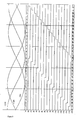
- the signal sequence is from the waveform of FIG. 8 for z. B. 5-bit interpolation accordingly refer to. It is particularly advantageous with this vectorial SIN / COS signal processing that that the vector used for the evaluation in the voltage amount at least the amplitude and up to 1.4 times the amplitude corresponds and thus always an almost constant high voltage potential Offers evaluation. In addition, signal-to-noise amplitudes are largely eliminated through the differential voltages forming the vector, so that precise Measurement signals can be used for high-precision interpolation. Another The advantage of the aforementioned vectorial interpolation is the direct signal processing to binary data that does not require additional and complex computer processing requirement. Only the tapping points via resistance dividers are corresponding to be dimensioned and tailored to the needs of the direct evaluation switch be forwarded.
- the location of the resistance network at which a comparator is determined is determined digitally last switched.
- the comparator that switched last is here the comparator COMP_1 with output Dn_1. That at the input of this comparator
- the present signal An_1 is now switched to an operational amplifier via a switch Sn_1 OPAMP switched and amplified to the analog signal Vn_1.
- This Signal is now proportional to the difference between the current angle and the through the Switching from COMP_1 given angle. This difference angle can now can be digitized by a suitable A / D converter and corrected as a fine value added to the fine values.
- a / D converter circuit With the introduction of an A / D converter circuit at this point, care must be taken that at least one of the outstanding characteristics of simplicity or absolute Real-time capability of the interpolator is not lost. If a relatively simple one A / D converters - like a sigma-delta converter - are used for the determination of the fine value requires many clock cycles. For very fast AD converters is the circuitry for interpolation even at low resolutions consuming.
- COMP_1 and COMP are the comparators that indicate that An_1 is smaller and An is larger than Uref, i.e. the angle you are looking for is located between the two fine values given by the comparators.
- the Both analog values An and An_1 are switched to two using switches Sn and Sn_1 identical amplifier OPAMP given and amplified to the signals Vn and Vn_1 and again fed into a resistor chain.
- Vn ⁇ Uref> applies Vn_1.
- the divided one Voltage is compared with Uref and analogous to the first stage digital output values F1 'to F4' an angle value (2 bits in the example) between the fine values determined.
- This A / D conversion in one clock period (Flash AD converter) is still low resolution with a few comparators well applicable.
- a switch solution with one or two is also in the second stage Comparators analogous to Figure 2 with COMP or COMP_1 and WS 1/2 executable. she is particularly advantageous compared to flash A / D converter when z. B. the resolution goes beyond 2 bits in this second stage.
- the circuit of FIG. 6 shows the principle of the one- and two-stage interpolator in the arrangement according to the invention. With simple integrated circuit components and thus cost-effective execution will also have full real-time capability achieved in use for high-resolution and fast measurement signal processing offer the required functional requirements.
- the fine values are determined as described in FIG. 3, the logic of ILOG also the logical changeover of the changeover contacts W II / I and W I / II to the operational amplifiers OPAMP1 and OPAMP 2 controls. The tension after the OPAMP's is then led to comparators, their signal sequence is used for fine value formation.
- the switches S are the most appropriate ones Interpolation resolution, e.g. B. depending on the speed of the Measuring device to be implemented using simple logic circuits. That's the easiest Case z. B. the selection of the interpolation levels (one or two levels) according to the Speed ranges of the measuring device can be easily accomplished.
- FIG. 7 shows the principle of offset compensation using the example of the comparator COMP.
- its INP input is separated from the signal source Sig I n by the switch S -sig and switched to the reference voltage U ref by the switch S ref .
- the transistors denoted by S1 to S8 By switching the transistors denoted by S1 to S8, currents flow through resistors U15 to U22, which generate a correction voltage at resistor U2 and thus at input INN.
- the resistors U15 to U18 (U19 to U22) symbolically represent binary graded current sources according to VDD (VSS). These current sources are graded in such a way that a compensation voltage up to the maximum expected offset voltage can be set taking U2 into account.
- the selection of suitable current sources is made by the logic OFF_LOG, which is activated each time the chip is reset or periodically. With the arrangement shown, the offset can easily be reduced to 1/16.
- the high-resolution measurement signals for fine and very fine values are in the industrial Ambient and measurement conditions exposed to corresponding disturbance variables. So the voltages supplied by the sensor are overlaid by noise and interference amplitudes, those in the measuring work area up to the highest adjustment speeds enough and not easy to filter.
- the basic mode of operation is used as an example for further processing of the fine and ultra-fine values, an asymmetrical adaptive digital filtering is used.
- Fig. 9 shows an advantageous embodiment for effectively fast and largely interference-free measurement signal acquisition.
- the adaptive digital filter F has as input the current ones obtained from the interpolator I. Fine and ultra-fine values Fin, which are filtered with the other fine and ultra-fine values Fout compared in feedback and according to certain basic filter parameters added up for comparison with certain and parameterizable limit values become. After one of the limit values has been reached, this is the logical consequence Filtered measured value output FOUT increased or decreased by one resolution step. Thereby are the basic filter parameters chosen according to the direction of movement expediently the parameter sizes Unsym and Lim accordingly easy to link. In block Z the basic absolute value and the filtered Fine / ultra-fine absolute value composed.
- the MAX clock cycles to be selected Cnt is therefore a first approximation of the appropriate integration time for a Measurement signal observation and is therefore also of selected filter parameters, such as z. B. Lim, Unsym dependent. The stronger the filtering and thus the higher the adaptation time constant is, the higher the MAX clock cycle number Cnt is to be selected.
- the inventive design of the adaptive interpolation filter can be symmetrical, asymmetrical, with fixed or variable parameters and their most varied Design links and is therefore not based on the illustrated embodiments limited. So the limit values or parameters z. B. from the Resolution of the measurement signal, the speed of the measuring device to be measured or also from external states of a machine control with special operating points dependent and entered.
- the flexible and versatile parameterizable The limits for self-adaptive measured value output are provided by advantageous filtering in the entire speed range for high-resolution interpolation measurement processing in z. B. particularly noisy industrial environments.
Landscapes
- Physics & Mathematics (AREA)
- General Physics & Mathematics (AREA)
- Transmission And Conversion Of Sensor Element Output (AREA)
- Analogue/Digital Conversion (AREA)
Abstract
Description

- Fig. 1:
- zeigt ein Prinzip herkömmlicher Interpolation mit einer Vielzahl von Komparatoren
- Fig. 2:
- zeigt das Prinzip der erfindungsgemäßen Interpolation mit Schalternetzwerk und einem bzw. zwei Komparatoren
- Fig. 3:
- zeigt ein Ausführungsbeispiel der Interpolation mit Schalternetzwerk und einem bzw. zwei Komparatoren unter Verwendung von drei Sinusvektoren
- Fig. 4:
- zeigt ein Prinzip der Zweistufen-Interpolation mit A/D-Wandlung für Feinstwerte
- Figur 5:
- zeigt ein Prinzip der Zweistufen-Interpolation mit zwei OPAMP- und Vergleichskomparatoren für Feinstwerte
- Fig. 6:
- zeigt ein Ausführungsbeispiel mit Schaltnetzwerk und einem bzw. zwei Komparatoren mit drei Sinus-Signalvektoren für Feinwertbildung sowie zwei OPAMP mit Vergleichskomparatoren zur Feinstwertbildung
- Fig. 7:
- zeigt ein Prinzip der Offset-Kompensation von Komparatoren und Operationsverstärker
- Fig. 8:
- zeigt den Signalverlauf im einstufigen Interpolator für Sinus-Signalvektoren
- Fig. 9:
- zeigt ein Blockschaltbild eines adaptiven Digitalfilters
- Fig. 10:
- zeigt das Ablaufdiagramm eines adaptiven Digitalfilters
Claims (14)
- Anordnung zur Interpolation eines von einer Messgröße abhängigen analogen Messsignals, das einem Spannungsteiler (Sp) zugeführt wird, dessen Abgriffsignale Komparatoren zugeführt werden, aus deren Ausgangssignalen die interpolierte Messgröße bestimmt wird, dadurch gekennzeichnet, dass die Abgriffsignale mittels Schalter (S1 bis S8), Komparatoren (Comp, Comp -1) zugeführt werden, deren Anzahl kleiner als die der Abgriffsignale ist und dass die Schalter (S1 bis S8) die Abgriffsignale folgerichtig an Komparatoren (Comp, Comp -1) anschalten.
- Anordnung nach Anspruch 1, dadurch gekennzeichnet, dass zwei Komparatoren (Comp, Comp -1) für jeweils zwei benachbarte Abgriffsignale vorgesehen sind.
- Anordnung nach Anspruch 2, dadurch gekennzeichnet, dass die zwei Komparatoren durch einen Komparator (Comp) ersetzt sind, dem die beiden benachbarten Abgriffsignale jeweils nacheinander( über WS 1 / 2) zugeführt werden.
- Anordnung nach einem der Ansprüche 1 bis 3, dadurch gekennzeichnet, daß das Messsignal einem stetigen Funktionsverlauf hat.
- Anordnung nach Anspruch 4, dadurch gekennzeichnet, dass das Messsignal einen linearen Zusammenhang zur Messgröße hat.
- Anordnung nach Anspruch 4, dadurch gekennzeichnet, dass das Messsignal aus der Kombination von Sinusfuktionen gebildet ist.
- Anordnung nach Anspruch 6, dadurch gekennzeichnet, dass drei der Signale +sin, -sin, +cos und -cos verwendet werden und dass das Kombinationssignal bereichsweise aus einem unterschiedlichen Paar der Signale +sin, -sin, +cos und -cos gebildet wird.
- Anordnung nach einem der Ansprüche 1 bis 7 gekennzeichnet, durch ihre Anwendung bei kombinierten Messsystemen, bei denen mittels Sensoren eine Absolutwertbestimmung durchgeführt wird und Zwischenwerte zwischen jeweils zwei benachbarten Absolutwerten durch ein Inkremental- Messsystem ermittelt werden.
- Anordnung nach Anspruch 8, dadurch gekennzeichnet, dass die Zusammensetzung der Absolutwerte und der Inkrementalwerte zu einem Gesamtabsolutwert am Sensor geführt wird.
- Anordnung nach einem der Ansprüche 1 bis 9, dadurch gekennzeichnet, dass ihr eine weitere Interpolationsstufe nachgeschaltet ist, in der die gewonnenen Differenzwerte der ersten Interpolation (Feinwerte) verstärkt und danach weiter zu Feinstwerten interpoliert werden.
- Anordnung nach einem der Ansprüche 1 bis 10, dadurch gekennzeichnet, dass ein Interpolationsfilter nachgeschaltet ist, in dem jeweils die Differenz des gefilterten Werts zum Aktuellen Messwert gebildet wird und dass diese Differenzen bewertet werden und dass bei Erreichen eines Grenzwerts der zuletzt gefilterte Messwert um einen Schritt erhöht oder erniedrigt wird.
- Anordnung nach Anspruch 11, dadurch gekennzeichnet, dass die zuletzt festgestellte Bewegungsrichtung der gelieferten Messwerte bei der Bewertung der aktuellen Messwerte berücksichtigt wird.
- Anordnung nach einem der Ansprüche 1 bis 12. dadurch gekennzeichnet, dass die Geschwindigkeit der Verstelleinrichtung für die Auswahl der Auflösung der Interpolation und/oder Filterung des Messsignals herangezogen wird.
- Verfahren zur Interpolation eines von einer Messgröße abhängigen analogen Messsignals, das einem Spannungsteiler (Sp) zugeführt wird, dessen Abgriffsignale Komparatoren zugeführt werden, aus deren Ausgangssignalen die interpolierte Messgröße bestimmt wird, dadurch gekennzeichnet, dass die Abgriffsignale mittels Schalter (S1 bis S8), Komparatoren (Comp, Comp -1) zugeführt werden, deren Anzahl kleiner als die der Abgriffsignale ist und dass die Schalter (S1 bis S8) die Abgriffsignale folgerichtig an Komparatoren (Comp, Comp -1) anschalten.
Applications Claiming Priority (2)
| Application Number | Priority Date | Filing Date | Title |
|---|---|---|---|
| DE10160835 | 2001-12-06 | ||
| DE10160835A DE10160835B4 (de) | 2001-12-06 | 2001-12-06 | Anordnung zur Interpolation eines Messsignals |
Publications (1)
| Publication Number | Publication Date |
|---|---|
| EP1318383A1 true EP1318383A1 (de) | 2003-06-11 |
Family
ID=7708806
Family Applications (1)
| Application Number | Title | Priority Date | Filing Date |
|---|---|---|---|
| EP02024075A Withdrawn EP1318383A1 (de) | 2001-12-06 | 2002-10-29 | Anordnung zur Interpolation eines Messignals |
Country Status (3)
| Country | Link |
|---|---|
| US (1) | US6741199B2 (de) |
| EP (1) | EP1318383A1 (de) |
| DE (1) | DE10160835B4 (de) |
Families Citing this family (11)
| Publication number | Priority date | Publication date | Assignee | Title |
|---|---|---|---|---|
| DE10301848B4 (de) | 2003-01-09 | 2014-10-09 | Anton Rodi | Messeinrichtung zur Erfassung von Größen, insbesondere von Winkeln oder Wegstrecken |
| CN1748220A (zh) * | 2003-02-06 | 2006-03-15 | 皇家飞利浦电子股份有限公司 | 伺服系统、包括伺服系统的装置、∑-△调制器、和包括∑-△调制器的集成电路 |
| US7119529B2 (en) * | 2003-06-12 | 2006-10-10 | Koninklijke Philips Electronics N.V. | Circuit arrangement with a resistor voltage divider chain |
| DE102004033990B3 (de) | 2004-07-14 | 2006-04-13 | Siemens Ag | Auswerteverfahren für ein analoges Erstsignal und ein analoges Zweitsignal sowie hiermit korrespondierende Auswerteschaltung |
| DE102004045849B4 (de) * | 2004-09-20 | 2014-06-05 | Anton Rodi | Messgeber mit Absolut-Signalverarbeitung und Inkremental-Signalausgabe |
| JP4213163B2 (ja) * | 2006-01-20 | 2009-01-21 | 三菱電機株式会社 | 磁気検出装置 |
| CN101482749A (zh) * | 2008-01-11 | 2009-07-15 | 鸿富锦精密工业(深圳)有限公司 | 主设备对从设备的自动定址系统 |
| JP5359776B2 (ja) * | 2009-10-23 | 2013-12-04 | セイコーエプソン株式会社 | 多センサー制御方法及び多センサー装置 |
| US9733106B2 (en) | 2013-05-24 | 2017-08-15 | Allegro Microsystems, Llc | Magnetic field sensor to detect a magnitude of a magnetic field in any direction |
| WO2014189733A1 (en) * | 2013-05-24 | 2014-11-27 | Allegro Microsystems, Llc | Magnetic field sensor for detecting a magnetic field in any direction above thresholds |
| CN114034238B (zh) * | 2021-11-19 | 2024-05-28 | 珠海润谷科技有限公司 | 一种补偿磁阻传感器迟滞的实现方法 |
Citations (4)
| Publication number | Priority date | Publication date | Assignee | Title |
|---|---|---|---|---|
| US3234361A (en) * | 1961-09-07 | 1966-02-08 | Ferranti Ltd | Apparatus for measuring movement of a cyclic wave pattern |
| EP0199826A1 (de) * | 1984-11-05 | 1986-11-05 | Fanuc Ltd. | Verfahren zur bestimmung der ortung |
| EP0220547A1 (de) * | 1985-10-08 | 1987-05-06 | Robert Bosch Gmbh | Drehzahlmesswertgeberschaltung |
| DE3918732A1 (de) * | 1988-07-11 | 1990-01-18 | Jenoptik Jena Gmbh | Verfahren und einrichtung zur interpolation sinusfoermiger messsignale, insbesondere solcher von fotoelektrischen messsystemen |
Family Cites Families (10)
| Publication number | Priority date | Publication date | Assignee | Title |
|---|---|---|---|---|
| US4631520A (en) * | 1984-06-08 | 1986-12-23 | Dynamics Research Corporation | Position encoder compensation system |
| JPS6275307A (ja) * | 1985-09-30 | 1987-04-07 | Toshiba Corp | 太陽センサ |
| CH670306A5 (de) * | 1986-11-13 | 1989-05-31 | Hans Ulrich Meyer | |
| JP2649390B2 (ja) * | 1988-10-12 | 1997-09-03 | キヤノン株式会社 | 信号内挿回路 |
| FR2722625B1 (fr) * | 1994-07-18 | 1996-10-04 | Thomson Consumer Electronics | Convertisseur a/n a comparaison multiple utilisant le principe d'interpolation |
| US5867116A (en) * | 1996-07-17 | 1999-02-02 | Analog Devices, Inc. | Multi-stage interpolating analog-to-digital conversion |
| US6121912A (en) * | 1998-09-30 | 2000-09-19 | National Semiconductor Corporation | Subranging analog-to-digital converter and method |
| CH706182B1 (de) * | 1999-11-18 | 2013-09-13 | Baumer Innotec Ag | Winkel- oder Weg-Messvorrichtung. |
| DE10035192C1 (de) * | 2000-07-20 | 2001-10-11 | Carl Mahr Holding Gmbh | Kapazitiver Wegaufnehmer für stromsparende Messgeräte |
| DE10059880B4 (de) * | 2000-12-01 | 2015-02-19 | Dr. Johannes Heidenhain Gmbh | Schaltungsanordnung und Verfahren zur Interpolation von Inkrementalsignalen |
-
2001
- 2001-12-06 DE DE10160835A patent/DE10160835B4/de not_active Expired - Fee Related
-
2002
- 2002-10-29 EP EP02024075A patent/EP1318383A1/de not_active Withdrawn
- 2002-12-06 US US10/314,178 patent/US6741199B2/en not_active Expired - Fee Related
Patent Citations (4)
| Publication number | Priority date | Publication date | Assignee | Title |
|---|---|---|---|---|
| US3234361A (en) * | 1961-09-07 | 1966-02-08 | Ferranti Ltd | Apparatus for measuring movement of a cyclic wave pattern |
| EP0199826A1 (de) * | 1984-11-05 | 1986-11-05 | Fanuc Ltd. | Verfahren zur bestimmung der ortung |
| EP0220547A1 (de) * | 1985-10-08 | 1987-05-06 | Robert Bosch Gmbh | Drehzahlmesswertgeberschaltung |
| DE3918732A1 (de) * | 1988-07-11 | 1990-01-18 | Jenoptik Jena Gmbh | Verfahren und einrichtung zur interpolation sinusfoermiger messsignale, insbesondere solcher von fotoelektrischen messsystemen |
Also Published As
| Publication number | Publication date |
|---|---|
| US20030107510A1 (en) | 2003-06-12 |
| DE10160835B4 (de) | 2011-02-17 |
| US6741199B2 (en) | 2004-05-25 |
| DE10160835A1 (de) | 2003-06-18 |
Similar Documents
| Publication | Publication Date | Title |
|---|---|---|
| DE69822030T2 (de) | Detektion von sich vorbeibewegenden magnetischen Gegenständen mit einem Schwellwertdetektor, wobei der Schwellwert ein prozentualer Anteil der Spitzenwerte ist | |
| DE19641035C2 (de) | Vorrichtung und Verfahren zur Positionsmessung | |
| EP1606590B1 (de) | Positionsmessverfahren und positionsmesssystem zur signalperioden-vervielfachung | |
| DE10160835B4 (de) | Anordnung zur Interpolation eines Messsignals | |
| DE3838291C1 (de) | ||
| DE102004046803A1 (de) | Verfahren zur Bestimmung der Winkelposition eines rotierenden Objekts und Drehgeber | |
| DE19707263A1 (de) | Selbstkalibrierende Sensoranordnung | |
| WO1998048284A2 (de) | Verfahren zur erkennung der drehrichtung eines rades mittels hall-sonden | |
| DE102004010613B4 (de) | Magnetfeldsensor und Verfahren zu seinem Betrieb | |
| EP1116076A2 (de) | Schaltungsanordnung und verfahren zum einstellen von schaltpunkten eines entscheiders | |
| EP1207372B1 (de) | Verfahren und Vorrichtung zur Konditionierung eines periodischen Analogsignals | |
| EP2288874A2 (de) | Verfahren zur bestimmung zumindest eines ersten internen parameters eines sensors | |
| AT401826B (de) | Messverfahren | |
| WO2001057478A1 (de) | Sensorvorrichtung und verfahren zur erzeugung eines ausgangssignals einer sensorvorrichtung | |
| EP0707198B1 (de) | Positionsmesseinrichtung | |
| DE102009006546B4 (de) | Schaltungsanordnung und Verfahren zum Bereitstellen eines aufbereiteten Messsignals | |
| DE102011077399A1 (de) | Geschwindigkeitssensor mit Costas-Schleife | |
| DE19506276B4 (de) | Verfahren und Schaltungsanordnung zur Interpolation von Sensorsignalen | |
| DE19938802B4 (de) | Verfahren und Schaltungsanorndung zur Interpolation | |
| DE102006049755B4 (de) | Schaltungsanordnung zur Konvertierung von Sensorsignalen | |
| EP0320596B1 (de) | Positionsmesseinrichtung mit Unterteilungsschaltung | |
| DE3843108C1 (de) | ||
| EP0390936B1 (de) | Schaltungsanordnung mit einem Gebersystem für weg- bzw. winkelabhängige Signale | |
| EP4597041B1 (de) | Vorrichtung und verfahren zur positions-, längen- oder winkelbestimmung | |
| EP1732309A1 (de) | Vorrichtung zur Ermittlung eines Maßes für eine Signaländerung und Verfahren zur Phasenregelung |
Legal Events
| Date | Code | Title | Description |
|---|---|---|---|
| PUAI | Public reference made under article 153(3) epc to a published international application that has entered the european phase |
Free format text: ORIGINAL CODE: 0009012 |
|
| AK | Designated contracting states |
Designated state(s): AT BE BG CH CY CZ DE DK EE ES FI FR GB GR IE IT LI LU MC NL PT SE SK TR |
|
| AX | Request for extension of the european patent |
Extension state: AL LT LV MK RO SI |
|
| 17P | Request for examination filed |
Effective date: 20031204 |
|
| AKX | Designation fees paid |
Designated state(s): AT BE BG CH CY CZ DE DK EE ES FI FR GB GR IE IT LI LU MC NL PT SE SK TR |
|
| RIN1 | Information on inventor provided before grant (corrected) |
Inventor name: GAERTNER, PETER, DR. Inventor name: RICHTER, HARALD, DR. Inventor name: RODI, ANTON |
|
| RIN1 | Information on inventor provided before grant (corrected) |
Inventor name: GAERTNER, PETER, DR. Inventor name: RICHTER, HARALD, DR. Inventor name: RODI, ANTON |
|
| RAP1 | Party data changed (applicant data changed or rights of an application transferred) |
Owner name: RODI, ANTON |
|
| 17Q | First examination report despatched |
Effective date: 20080529 |
|
| STAA | Information on the status of an ep patent application or granted ep patent |
Free format text: STATUS: THE APPLICATION IS DEEMED TO BE WITHDRAWN |
|
| 18D | Application deemed to be withdrawn |
Effective date: 20120412 |