EP1312883A2 - Vorrichtung zum Verschliessen des Bodenabstichs eines metallurgischen Gefässes für flüssigen Stahl, insbesondere eines Elektroschmelzofens - Google Patents
Vorrichtung zum Verschliessen des Bodenabstichs eines metallurgischen Gefässes für flüssigen Stahl, insbesondere eines Elektroschmelzofens Download PDFInfo
- Publication number
- EP1312883A2 EP1312883A2 EP02022821A EP02022821A EP1312883A2 EP 1312883 A2 EP1312883 A2 EP 1312883A2 EP 02022821 A EP02022821 A EP 02022821A EP 02022821 A EP02022821 A EP 02022821A EP 1312883 A2 EP1312883 A2 EP 1312883A2
- Authority
- EP
- European Patent Office
- Prior art keywords
- cylinder
- plunger
- piston
- threaded
- press
- Prior art date
- Legal status (The legal status is an assumption and is not a legal conclusion. Google has not performed a legal analysis and makes no representation as to the accuracy of the status listed.)
- Withdrawn
Links
Images






Classifications
-
- F—MECHANICAL ENGINEERING; LIGHTING; HEATING; WEAPONS; BLASTING
- F27—FURNACES; KILNS; OVENS; RETORTS
- F27D—DETAILS OR ACCESSORIES OF FURNACES, KILNS, OVENS OR RETORTS, IN SO FAR AS THEY ARE OF KINDS OCCURRING IN MORE THAN ONE KIND OF FURNACE
- F27D3/00—Charging; Discharging; Manipulation of charge
- F27D3/15—Tapping equipment; Equipment for removing or retaining slag
- F27D3/1509—Tapping equipment
- F27D3/1536—Devices for plugging tap holes, e.g. plugs stoppers
-
- F—MECHANICAL ENGINEERING; LIGHTING; HEATING; WEAPONS; BLASTING
- F27—FURNACES; KILNS; OVENS; RETORTS
- F27B—FURNACES, KILNS, OVENS OR RETORTS IN GENERAL; OPEN SINTERING OR LIKE APPARATUS
- F27B3/00—Hearth-type furnaces, e.g. of reverberatory type; Electric arc furnaces ; Tank furnaces
- F27B3/10—Details, accessories or equipment, e.g. dust-collectors, specially adapted for hearth-type furnaces
- F27B3/19—Arrangements of devices for discharging
-
- F—MECHANICAL ENGINEERING; LIGHTING; HEATING; WEAPONS; BLASTING
- F27—FURNACES; KILNS; OVENS; RETORTS
- F27D—DETAILS OR ACCESSORIES OF FURNACES, KILNS, OVENS OR RETORTS, IN SO FAR AS THEY ARE OF KINDS OCCURRING IN MORE THAN ONE KIND OF FURNACE
- F27D3/00—Charging; Discharging; Manipulation of charge
- F27D3/12—Travelling or movable supports or containers for the charge
- F27D2003/125—Charging cars, lift trolleys
- F27D2003/127—Charging cars, lift trolleys for carrying pots
Definitions
- the invention relates to a device for closing the floor tapping metallurgical vessel for liquid steel, in particular an electric melting furnace, that in melting mode by means of a sliding closing plate and above located refractory material is closed, the melt during of the rack by opening the cover plate through the tap hole and that in the presence of residual melt by filling the tap hole with the refractory material and a plunger that can be moved from bottom to top lockable and the locking plate can be moved into its locking position is.
- Such a device is known from DE 32 30 646 C1.
- the press channel for the refractory material in an arc from the horizontal to the vertical guided is known.
- granular refractory material is very difficult to get around an arched pipe channel can be pushed and turned again and again Gaps, i.e. Result in voids that significantly degrade the work result.
- this design sets the durability of Darning mass with a cartridge in advance, which must be kept in stock.
- the invention has for its object the disadvantages of the arcuate press channels for free-flowing materials and without cartridges and others Mixtures of stuffing with refractory materials for vertical ducts get along.
- the stated object is achieved according to the invention in the device described at the outset solved that the plunger by means of one in several stations horizontally movable carriage, in which granules in the cylinder of the plunger is introduced and prepared on a press piston axis aligned with the tap hole the granulate, filling the tap hole fully, can be inserted under pressure is.
- This makes it necessary to interact with the slide plate in practice enables the displacement of those located in the tap hole Remnants of melt, slag and the like Like. Allows.
- the procedure is unlimited repeatable without special effort.
- the device is robust and suitable for steelworks.
- the device can also be retrofitted to all systems.
- the invention can get by, as proposed by further features will be that a first filling station in the area of the metallurgical vessel of the cylinder with granulate, a second station for coating the granulate with a binder, a third station for heating the binder until sintering and a horizontal rail track is provided up to below the metallurgical vessel are.
- a top layer of the granulate is advantageous covered with binder. Heating the binder leads to a sintered plate on top of the granulate. At the moment of contact between liquid steel and granulate prevents the sintered plate from floating up in the granulate Steel column.
- the system of stations can be expanded by the fact that in the area of Vessel wall of the metallurgical vessel an additional, fourth station for the Lowering the plunger is provided in the cylinder.
- Another addition is that the additional station with a press tool is provided for lowering the plunger.
- the pressing tool is used as a cantilever a vertical axis position on the vessel wall of the metallurgical vessel is attached.
- the design of the car can be used in several ways. So after further features provided that the cylinder on the circumference by means of a guide Height adjustable in the carriage frame and by means of springs distributed over the circumference can be reset to a basic position.
- the carriage is further designed so that the guide is off the cylinder there are axially fixed support arms that are parallel to the carriage frame are guided to the cylinder extending and attached guide rods.
- Another embodiment is that the springs for resetting the Cylinder between the upper projections of the carriage frame and lower support arms of the cylinder are clamped.
- the movability of the carriage on the furnace platform is designed in such a way that the Wheels of the car between a cover plate, which is a cutout for the cylinder has, and brackets attached to the carriage frame are rotatably mounted.
- the functions for inserting the granulate into the cylinder and inserting it in the tap hole depend on the suitable design of the plunger.
- a particularly noteworthy construction results from the fact that the plunger in the cylinder by means of a main piston sealing against the granulate and in the center arranged, from below supporting telescope sections and an end piston arranged in the base region of the cylinder is formed.
- the pressure force for the plunger can be generated hydraulically and the The overall height of the plunger-cylinder unit becomes very low.
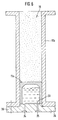
- the hydraulic embodiment is then designed according to further features, that in the cylinder a single, sealing plunger by a liquid Pressure medium is actuated by the connections in a cylinder down occluding bottom can be added or removed.
- This design has the advantage of one to be able to achieve a very low overall height.
- the sealing effects can also be reinforced by the fact that between the ring attachment and a pressure medium ring seal and in the foot area of the Press pistons are each made of Teflon guide bands.
- a practical embodiment is designed such that the plunger is by means of at least one pivoted, drivable threaded spindle and one in the plunger stationary threaded nut and a longitudinal groove in the cylinder wall, in which slides a sliding block fixed on the plunger, can be actuated, the rotary drive motor and a primary gear for the threaded spindle mounted on the cylinder base are.
- the rotary drive motor and the primary gearbox are mounted on the outside of the cylinder wall.
- the primary gear and the rotary drive motor is arranged on a bracket at the cylinder base are.
- a primary gear and a rotary drive motor each symmetrical to the plunger axis on the outside of the cylinder wall fixed console are arranged and that each of the primary gear Threaded spindle runs up to the cylinder base, which in each case by means of a yoke parallel guidance of the cylinder wall is adjustable at stroke height and one each Threaded nut carries.
- a further advantageous construction results from the fact that the press piston in the piston stroke is mechanically and / or hydraulically adjustable in stages.
- This construction can e.g. to be designed so that one or more Lifting stages mechanically by means of the threaded spindles and threaded nuts and the last stroke level hydraulically by means of synchronous piston-cylinder units are adjustable.
- this design is such that a first Stroke by means of a threaded spindle acting centrally under the head of the plunger, a second stroke by means of several side threaded spindles and third stroke level by means of one or more pairs of hydraulic piston-cylinder units are adjustable.
- a different type of drive design is based on a completely different one Principle chosen so that the distributed over the circumference of the cylinder Lead screws from an input flange of the cylinder at full stroke height run that a threaded nut with a first on each threaded spindle Magnet is arranged with an opposite second magnet corresponds within the relatively short press piston, with at least one primary gear and the rotary drive motor for the threaded spindle on the cylinder base are stationary.
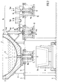
- an electric melting furnace 2 is shown as the metallurgical vessel 1, the in particular is not tiltable.
- the electric melting furnace 2 rests on supports 3, which are support yourself on the oven platform 4.
- the molten steel 9 flows through the tap hole 7 with the melt jet 10 in the pan 6a.
- the closure plate 8 is closed.
- a plunger 11a which is arranged on a carriage 12.
- the carriage 12 is along a railroad track 13 move past several stations 14 on the furnace platform 4.
- the first station 14a is the cylinder 11b with a fire-resistant granulate 15 filled.
- the plunger 11a When filling with granules 15, the plunger 11a is in it lowest position.
- To press the granules 15 into the tap hole 7 Press plunger 11a set all the way up.
- the stroke of the plunger 11a must be as large as the length of tap hole 7, i.e. the piston stroke is about 4 times large as the piston diameter.
- the granules 15 are obtained in a second station 14b a layer of binder 16 and in a third station 14c this binder layer 16 heated and thus sintered.
- the plunger is in a fourth station 14d 11a pressed down to compress the granules 15.
- the carriage 12 is driven so far under the electric melting furnace 2 until the plunger axis 11c is aligned with the axis of the tap hole 7. Then the cylinder 11b is pressed against the closing plate 8, for which purpose in the carriage 12 a short-stroke hydraulic cylinder 17 is provided, the closure plate 8 for a short time opened and the plunger 11 a together with the granules 15 in the tap hole 7 pressed straight up from the bottom, making the tap hole 7 completely filled tightly with granules 15.
- the closure plate 8 can briefly in Be closed position, the cylinder 11 b temporarily seals.
- the ladle transport trolley for the purpose of filling the tap hole 7 6 moved away with the pan 6a, so that the carriage 12 in the described Position can be brought.
- the carriage 12 is together with the Cylinder 11b designed as low as possible.
- the removal of the full pan 6a should not be possible for any reason is as follows described procedure for the closure plate 8 and the tap hole 7 anyway possible.
- the carriage 12 can be used regardless of the pan position be moved back and forth.
- the pan 6a can therefore also under the Cars 12 are located.
- an additional, fourth station 14d for lowering of the plunger 11a in the cylinder 11b.
- the additional station 14d is provided with a pressing tool 18 for lowering the pressing piston 11a.
- the pressing tool 18 is designed as a boom 19 and is vertical Axis position 18a attached to the vessel wall 1 a of the metallurgical vessel 1.
- the sequence of functions for a trouble-free ladle transport is described below:
- the molten steel 9 runs when the closing plate 8 is open, whereby the closing plate 8 can consist of a normal knife gate valve (above all, no special design is required), through the tap hole 7 into the pan 6a.
- the closing plate 8 is closed.
- the pan 6a is moved away.
- the carriage 12 with the cylinder 11b travels under the closure plate 8, the cylinder 11b being filled with granules 15 up to its edge.
- the cylinder 11b is moved sealingly vertically under the closure plate 8.
- the plunger 11 a presses the filling material against the liquid steel column and moves this through the tap hole 7 upwards until the vessel lining is reached Sealing plate 8 is closed through the filling material (granulate 15).
- the cylinder 11b is moved down.
- the pan 6a is on the side with the car 12 drove away.
- the carriage 12 moves away to the side, regardless of the pan position.
- An empty pan 6a can be under the metallurgical Vessel 1 can be driven.
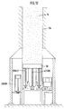
- the carriage 12 is shown on an enlarged scale in FIG. 3.
- the cylinder 11b is adjustable in height on the circumference 11d by means of a guide 20 in the carriage frame 12a and by means of springs 21 distributed over the circumference 11d into its lower basic position resettable. The force of the springs 21 therefore always presses the cylinder 11b into its lower one Home position back.
- the guide 20 is axially spaced from the cylinder 11b attached support arms 22 formed in the carriage frame 12a parallel to the cylinder 11b extending and fastened guide rods 23 are guided.
- the feathers 21 are for the return of the cylinder 11b between projections 24 of the carriage frame 12a and lower support arms 25 of the cylinder 11b clamped.
- the carriage 12 itself is guided by wheels 26 which are between a cover plate 27, which has a cutout 27a for the cylinder 11b and on the carriage frame 12a, the wheels 26 are rotatably supported on brackets 28.
- FIG. 4 shows a top view of the carriage 12. Corresponding to the four wheels 26 the cylinder 11b is guided on the four guide rods 23 offset by 90 °.
- FIGS. 5A and 5B A preferred embodiment of the plunger 11a is shown in FIGS. 5A and 5B.
- the pressing piston 11a is formed in the cylinder 11b by means of a main piston 11e sealing against the granulate 15 and in the center, from below supporting telescopic sections 29 and a closing piston 31 arranged in the base region 30 of the cylinder 11b.
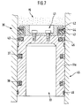
- the plunger 11a or the main piston 11e is in the lower region (FIG. 7) one or more ring seals 37, 38 against the liquid pressure medium 33 and sealed in the head region 39 with a separate granular ring seal 40.
- a ring attachment 42 is attached, in addition to a pressure medium ring seal 43 carries a metal wiper ring 44.
- a guide bands 46 made of Teflon (PTFE) are used.
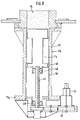
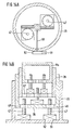
- the drive for the plunger 11a can alternatively (Fig. 8) by means of central and / or several, distributed over the circumference threaded spindles 47 and a stationary Threaded nut 48 in the press piston 11a in the uppermost position - e.g. as a single spindle drive - be formed.
- a sliding block is provided in the plunger 11 a as an anti-rotation device 49 is provided, which slides in a longitudinal groove 50 in the cylinder wall 11f.
- the threaded spindle 47 is by a rotary drive motor 51 and a primary gear 52nd driven, which are mounted on a cylinder base 11g.
- both the rotary drive motor 51 and the primary gear 52 mounted on the outside of the cylinder wall 11f on brackets 53 on the cylinder base 11g be (Fig. 9).
- synchronized lead screws 47 are on both Pages arranged.
- a threaded spindle is provided by a primary gear 52 47 to the cylinder base 11g, which are parallel by means of a yoke 54
- Guide 55 guided through slots in the cylinder wall 11f at lifting height is adjustable and each carries a threaded nut 48.
- FIGS. 10 and 11 A drive alternative for the plunger 11 a is shown in FIGS. 10 and 11.
- the plunger 11a forms a head 56, under which several, over the circumference 11d distributed sleeves 57 are provided as threaded nuts 48 for the threaded spindles 47 are.
- the threaded spindles 47 are stationary and with the respective primary gear 52 connected and in each case together with the rotary drive motor 51 mounted on the base area 30 on the cylinder base 11g.
- the sleeves 57 each have a sliding block 49, which in its longitudinal groove 50 in the cylinder wall 11f slides.
- the plunger 11a is extended, the sleeves 57 being fully extended are.
- the plunger 11a can gradually and mechanically and / or hydraulically in the piston stroke be adjusted.
- One or more lifting stages 58, 59 can be mechanical by means of the threaded spindles 47 and threaded nuts 48 and the third lifting stage 60 can be set hydraulically by means of synchronously operating piston-cylinder units 61 become (Fig. 12).
- the first lifting stage 58 works centrally by means of a the head 56 of the plunger 11a engaging threaded spindle 47, a second Lift stage 59 by means of several side threaded spindles 47 and the third lift stage 60 by means of one or more pairs of hydraulic piston-cylinder units 61.
- FIG. 13 is a further alternative design for the lifting drive of the plunger 11a:
- the threaded spindles distributed over the circumference 11d of the cylinder 11b 47 run from an input flange 62 at full lift height 63.
- At least one primary gearbox 52 and the rotary drive motor 51 for the threaded spindle 47 each have the stationary threaded spindle 47 on the cylinder base 11g.
- 14A and 14B is a further alternative design (in plan view) the plunger 11a with cylinder 11b from individual telescopic sections 29, which slide into each other and are each provided with a bottom 66, whereby the threaded spindles 47 and the threaded nuts 48 each on a bottom 66 are stored.
- For the threaded spindles 47 are 66 in opposite floors in each case through openings 67 are arranged.
- the threaded spindles 47 are as described each driven by a rotary drive motor 51 with primary gear 52.
- the rotary drive motor 51 and the primary gear 52 can also outside be arranged (Fig. 14A) and connect the threaded spindles in the lowest stage 47 / threaded nuts 48 with a horizontal shaft 68.
Landscapes
- Engineering & Computer Science (AREA)
- Mechanical Engineering (AREA)
- General Engineering & Computer Science (AREA)
- Furnace Charging Or Discharging (AREA)
- Refinement Of Pig-Iron, Manufacture Of Cast Iron, And Steel Manufacture Other Than In Revolving Furnaces (AREA)
- Vertical, Hearth, Or Arc Furnaces (AREA)
Abstract
Description
- Fig. 1
- eine Gesamtansicht einer Schmelzofenanlage mit den Stationen für das Füllen des Zylinders mit Granulat, mit einem E-Ofen beim Abstich,
- Fig. 2
- dieselbe Gesamtansicht der Schmelzofenanlage mit eingefahrenem Wagen für das Granulat,
- Fig. 3
- der Wagen mit dem Presskolben und dem Zylinder für das Granulat in Seitenansicht,
- Fig. 4
- eine Draufsicht auf den Wagen mit Zylinder für das Granulat,
- Fig. 5A
- einen senkrechten Schnitt durch den Zylinder mit Presskolben in der oberen Stellung,
- Fig. 5B
- denselben Schnitt wie Fig. 5A , in der der Zylinder mit Granulat gefüllt ist,
- Fig. 6
- eine alternative Ausführungsform für den Presskolben mit einem Hydrozylinder im senkrechten Schnitt,
- Fig. 7
- den Presskolben im axialen Schnitt mit Einzelheiten der Abdichtung,
- Fig. 8
- einen senkrechten Schnitt durch eine alternative Ausführung des Presskolbens mit Spindelantrieb,
- Fig. 9
- einen weiteren senkrechten Schnitt durch den Presskolben mit einer weiteren Alternativen einer Doppelspindel-Ausführung,
- Fig. 10
- eine andere alternative Ausführungsform im senkrechten Schnitt mit unter dem Presskolbenkopf angeordneten Spindeln in eingezogener Stellung der Spindeln,
- Fig. 11
- die Ausführungsform der Fig. 10 in Mittelposition bei ausgefahrenen Spindeln,
- Fig. 12
- eine alternative Ausführungsform mit mechanisch-hydraulischem Antrieb für den Presskolben,
- Fig. 13
- eine weitere alternative Ausführungsform für den Antrieb des Presskolbens im senkrechten Schnitt mit Magneten,
- Fig. 14A
- eine Draufsicht auf eine weitere alternative Bauweise mit mehreren Spindel-Hub-Elementen und
- Fig. 14B
- den zu Fig. 14A gehörenden axialen Längsschnitt.
- 1
- metallurgisches Gefäß
- 1a
- Gefäßwandung
- 2
- Elektroschmelzofen
- 3
- Stütze
- 4
- Ofenbühne
- 5
- Hüttenflur
- 6
- Pfannentransportwagen
- 6a
- Pfanne
- 7
- Abstichloch
- 8
- Verschlussplatte
- 9
- Stahlschmelze
- 9a
- Restschmelze
- 10
- Schmelzenstrahl
- 11a
- Presskolben
- 11b
- Zylinder
- 11 c
- Presskolben-Achse
- 11d
- Umfang
- 11e
- Hauptkolben
- 11f
- Zylinderwandung
- 11g
- Zylinderfuß
- 12
- Wagen
- 12a
- Wagenrahmen
- 13
- Schienenbahn
- 14
- Stationen
- 14a
- erste Station
- 14b
- zweite Station
- 14c
- dritte Station
- 14d
- vierte Station
- 15
- Granulat
- 16
- Schicht / Bindemittel
- 17
- Hydraulikzylinder
- 18
- Presswerkzeug
- 18a
- senkrechte Achsstellung
- 19
- Ausleger
- 20
- Führung
- 21
- Federn
- 22
- Stützarme
- 23
- Führungsstangen
- 24
- Vorsprünge
- 25
- Stützarme
- 26
- Räder
- 27
- Deckplatte
- 27a
- Ausschnitt
- 28
- Konsolen
- 29
- Teleskop-Abschnitte
- 30
- Sockelbereich
- 31
- Abschlusskolben
- 32
- Zylinder-Innenfläche
- 33
- flüssiges Druckmittel
- 34
- Anschluss
- 35
- Anschluss
- 36
- Boden
- 37
- Ringdichtung
- 38
- Ringdichtung
- 39
- Kopfbereich
- 40
- Granulat-Ringdichtung
- 41
- Stirnseite
- 42
- Ringaufsatz
- 43
- Druckmittel-Ringdichtung
- 44
- Metallabstreifer-Ring
- 45
- Fußbereich des Presskolbens
- 46
- Führungsbänder
- 47
- Gewindespindel
- 48
- Gewindemutter
- 49
- Gleitstein
- 50
- Längsnut
- 51
- Drehantriebsmotor
- 52
- Vorschaltgetriebe
- 53
- Konsolen
- 54
- Joch
- 55
- parallele Führung
- 56
- Kopf
- 57
- Hülsen
- 58
- erste Hubstufe
- 59
- zweite Hubstufe
- 60
- dritte Hubstufe
- 61
- Kolben-Zylinder-Einheit
- 62
- Eingangs-Flansch
- 63
- volle Hubhöhe
- 64
- Magnet
- 65
- Magnet
- 66
- Boden
- 67
- Durchgangsöffnung
- 68
- horizontale Welle
Claims (26)
- Vorrichtung zum Verschließen des Bodenabstichs eines metallurgischen Gefäßes für flüssigen Stahl, insbesondere eines Elektroschmelzofens, der im Schmelzbetrieb mittels einer verschiebbaren Verschlussplatte und darüber befindlichem feuerfestem Material verschlossen ist, dessen Schmelze während des Abstichs durch Öffnen der Verschlussplatte durch das Abstichloch abgestochen wird und der bei Vorhandensein einer Restschmelze durch Befüllen des Abstichlochs mit dem feuerfesten Material und eines senkrecht von unten nach oben verstellbaren Presskolbens verschließbar und die Verschlussplatte in ihre Verschlusstellung verschiebbar ist,
dadurch gekennzeichnet, dass der Presskolben (11 a) mittels eines in mehreren Stationen (14) horizontal verfahrbaren Wagens (12), in denen Granulat (15) in den Zylinder (11b) des Presskolbens (11a) eingebracht und vorbereitet wird, auf einer mit dem Abstichloch (7) fluchtenden Presskolben-Achse (11c) und dabei das Granulat (15), das Abstichloch (7) voll ausfüllend, unter Druck einbringbar ist. - Vorrichtung nach Anspruch 1,
dadurch gekennzeichnet, dass der Zylinder (11b) für den Presskolben (11a) auf dem Wagen (12) höhenverstellbar zum Anpressen des Zylinders (11b) gegen die Verschlussplatte (8) ist. - Vorrichtung nach den Ansprüchen 1 und 2,
dadurch gekennzeichnet, dass im Bereich des metallurgischen Gefäßes (1) eine erste Station (14a) zum Befüllen des Zylinders (11b) mit Granulat (15), eine zweite Station (14b) zum Beschichten des Granulats (15) mit einem Bindemittel (16), eine dritte Station (14c) zum Beheizen des Bindemittels (16) bis zum Versintern und eine horizontale Schienenbahn (13) bis unter das metallurgische Gefäß (1) vorgesehen sind. - Vorrichtung nach einem der Ansprüche 1 bis 3,
dadurch gekennzeichnet, dass im Bereich der Gefäßwandung (1a) des metallurgischen Gefäßes (1) eine zusätzliche, vierte Station (14d) für das Absenken des Presskolbens (11a) im Zylinder (11 b) vorgesehen ist. - Vorrichtung nach Anspruch 4,
dadurch gekennzeichnet, dass die zusätzliche Station (14d) mit einem Presswerkzeug (18) für das Absenken des Presskolbens (11a) versehen ist. - Vorrichtung nach einem der Ansprüche 4 oder 5,
dadurch gekennzeichnet, dass das Presswerkzeug (18) als Ausleger (19) mit einer senkrechten Achsstellung (18a) an der Gefäßwandung (1a) des metallurgischen Gefäßes (1) befestigt ist. - Vorrichtung nach einem der Ansprüche 1 bis 6,
dadurch gekennzeichnet, dass der Zylinder (11b) am Umfang (11d) mittels einer Führung (20) im Wagenrahmen (12a) höhenverstellbar und mittels über den Umfang (11d) verteilten Federn (21) in eine Grundstellung rückstellbar ist. - Vorrichtung nach einem der Ansprüche 1 bis 7,
dadurch gekennzeichnet, dass die Führung (20) aus am Zylinder (11b) in axialem Abstand befestigten Stützarmen (22) besteht, die in am Wagenrahmen (12a) parallel zum Zylinder (11b) verlaufenden und befestigten Führungsstangen (22) geführt sind. - Vorrichtung nach einem der Ansprüche 7 oder 8,
dadurch gekennzeichnet, dass die Federn (21) für die Rückstellung des Zylinders (11b) zwischen oberen Vorsprüngen (24) des Wagenrahmens (12a) und unteren Stützarmen (25) des Zylinders (11b) eingespannt sind. - Vorrichtung nach einem der Ansprüche 1 bis 9,
dadurch gekennzeichnet, dass die Räder (26) des Wagens (12) zwischen einer Deckplatte (27), die einen Ausschnitt (27a) für den Zylinder (11b) aufweist, und am Wagenrahmen (12a) angebrachter Konsolen (28) drehgelagert sind. - Vorrichtung nach einem der Ansprüche 1 bis 10,
dadurch gekennzeichnet, dass der Presskolben (11a) in dem Zylinder (11b) mittels eines gegen das Granulat (15) dichtenden Hauptkolbens (11e) und in dessen Zentrum angeordneten, von unten stützenden Teleskop-Abschnitte (29) und eines im Sokkelbereich (30) des Zylinders (11b) angeordneten Abschlusskolbens (31) gebildet ist. - Vorrichtung nach einem der Ansprüche 1 bis 11,
dadurch gekennzeichnet, dass die Zylinder-Innenfläche (32) mit Wolframkarbid beschichtet ist. - Vorrichtung nach einem der Ansprüche 1 bis 10 und 11,
dadurch gekennzeichnet, dass in dem Zylinder (11b) ein einziger, abdichtender Presskolben (11a) durch ein flüssiges Druckmittel (33) betätigbar ist, das durch Anschlüsse (34, 35) in einem den Zylinder (11b) nach unten verschließenden Boden (36) zu- oder abführbar ist. - Vorrichtung nach einem der Ansprüche 1 bis 13,
dadurch gekennzeichnet, dass der Presskolben (11a) bzw. der Hauptkolben (11e) im unteren Bereich mit einer oder mehreren Ringdichtungen (37, 38) gegen das flüssige Druckmittel (33) und im Kopfbereich (39) mit einer separaten Granulat-Ringdichtung (40) versehen ist. - Vorrichtung nach einem der Ansprüche 1 bis 14,
dadurch gekennzeichnet, dass auf der Stirnseite (41) des Presskolbens (11a) bzw. des Hauptkolbens (11e) ein Ringaufsatz (42) befestigt ist, der neben einem Dichtungsring (43) einen Metallabstreifer-Ring (44) trägt. - Vorrichtung nach einem der Ansprüche 1 bis 15,
dadurch gekennzeichnet, dass zwischen dem Ringaufsatz (42) und einer Druckmittel-Ringdichtung (43) und im Fußbereich (45) des Presskolbens (11a) jeweils Führungsbänder (46) aus Teflon eingesetzt sind. - Vorrichtung nach einem der Ansprüche 1 bis 12,
dadurch gekennzeichnet, dass der Presskolben (11a) mittels einer zentrischen und / oder mehreren, über den Umfang verteilter Gewindespindeln (47) und ortsfesten oder höhenverstellbaren Gewindemuttern (48) im Presshub verstellbar ist. - Vorrichtung nach einem der Ansprüche 1 bis 12 und 17,
dadurch gekennzeichnet, dass der Presskolben (11a) mittels zumindest einer drehgelagerten, antreibbaren Gewindespindel (47) und einer im Presskolben (11a) stationären Gewindemutter (48) sowie einer Längsnut (50) in der Zylinderwandung (11f), in der ein am Presskolben (11a) fester Gleitstein (49) gleitet, betätigbar ist, wobei der Drehantriebsmotor (51) und ein Vorschaltgetriebe (52) für die Gewindespindel (47) am Zylinderfuß (11g) gelagert sind. - Vorrichtung nach Anspruch 17,
dadurch gekennzeichnet, dass der Drehantriebsmotor (51) und das Vorschaltgetriebe (52) außen an der Zylinderwandung (11f) gelagert sind. - Vorrichtung nach einem der Ansprüche 17 oder 18,
dadurch gekennzeichnet, dass das Vorschaltgetriebe (52) und der Drehantriebsmotor (51) auf einer Konsole (53) am Zylinderfuß (11g) angeordnet sind. - Vorrichtung nach einem der Ansprüche 17 oder 18,
dadurch gekennzeichnet, dass ein Vorschaltgetriebe (52) und ein Drehantriebsmotor (51) jeweils symmetrisch zur Presskolben-Achse (12c) auf einer jeweils außen an der Zylinderwandung (11f) befestigten Konsole (53) angeordnet sind und dass vom Vorschaltgetriebe (52) jeweils eine Gewindespindel (47) bis zum Zylinderfuß (11 g) verläuft, die mittels eines Jochs (54) in jeweils einer parallelen Führung (55) der Zylinderwandung ( 11f auf Hubhöhe verstellbar ist und jeweils eine Gewindemutter (48) trägt. - Vorrichtung nach Anspruch 17 oder 18,
dadurch gekennzeichnet, dass der Presskolben (11 a) unter seinem Kopf (56) mehrere über den Umfang (11d) verteilte Hülsen (57) als Gewindemuttern (48) für die Gewindespindeln (47) aufweist und dass die Gewindespindeln (47) stationär sind und mit dem jeweiligen Vorschaltgetriebe (52) verbunden sind, die jeweils zusammen mit dem Drehantriebsmotor (51) auf dem Sockelbereich (30) am Zylinderfuß (11g) gelagert sind. - Vorrichtung nach Anspruch 17 oder 18,
dadurch gekennzeichnet, dass der Presskolben (11a) im Kolbenhub stufenweise mechanisch und / oder hydraulisch verstellbar ist. - Vorrichtung nach Anspruch 23,
dadurch gekennzeichnet, dass eine oder mehrere Hubstufen (58) mechanisch mittels den Gewindespindeln (47) und Gewindemuttern (48) und die letzte Hubstufe hydraulisch mittels synchron arbeitenden Kolben-Zylinder-Einheiten (58) verstellbar sind. - Vorrichtung nach den Ansprüchen 23 oder 24,
dadurch gekennzeichnet, dass eine erste Hubstufe (58) mittels einer zentrisch unter dem Kopf (56) des Presskolbens (11a) angreifenden Gewindespindel (47), eine zweite Hubstufe (59) mittels mehrerer Seiten-Gewindespindeln (47) und die dritte Hubstufe (60) mittels eines oder mehrerer Paare von hydraulischen Kolben-Zylinder-Einheiten (61) einstellbar sind. - Vorrichtung nach einem der Ansprüche 17 oder 18,
dadurch gekennzeichnet, dass die über den Umfang (11d) des Zylinders (11b) verteilten Gewindespindeln (47) von einem Eingangs-Flansch ( 62) des Zylinders (11b) auf voller Hubhöhe (63) verlaufen, dass auf einer Gewindespindel (47) jeweils eine Gewindemutter (48) mit einem ersten Magneten (64) angeordnet ist, der mit einem gegenüberliegenden zweiten Magneten (65) innerhalb des relativ kurzen Presskolbens (11a) korrespondiert, wobei zumindest ein Vorschaltgetriebe (52) und der Drehantriebsmotor (51) für die Gewindespindel (47) jeweils am Zylinderfuß (11g) stationär gelagert sind.
Applications Claiming Priority (2)
| Application Number | Priority Date | Filing Date | Title |
|---|---|---|---|
| DE10156455 | 2001-11-16 | ||
| DE2001156455 DE10156455A1 (de) | 2001-11-16 | 2001-11-16 | Vorrichtung zum Verschließen des Bodenabstichs eines metallurgischen Gefäßes für flüssigen Stahl, insbesondere eines Elektroschmelzofens |
Publications (2)
| Publication Number | Publication Date |
|---|---|
| EP1312883A2 true EP1312883A2 (de) | 2003-05-21 |
| EP1312883A3 EP1312883A3 (de) | 2003-12-03 |
Family
ID=7706057
Family Applications (1)
| Application Number | Title | Priority Date | Filing Date |
|---|---|---|---|
| EP02022821A Withdrawn EP1312883A3 (de) | 2001-11-16 | 2002-10-12 | Vorrichtung zum Verschliessen des Bodenabstichs eines metallurgischen Gefässes für flüssigen Stahl, insbesondere eines Elektroschmelzofens |
Country Status (2)
| Country | Link |
|---|---|
| EP (1) | EP1312883A3 (de) |
| DE (1) | DE10156455A1 (de) |
Cited By (2)
| Publication number | Priority date | Publication date | Assignee | Title |
|---|---|---|---|---|
| WO2011089054A1 (de) * | 2010-01-20 | 2011-07-28 | Tmt Tapping-Measuring-Technology Gmbh | Stichlochstopfmaschinenkanone für metallurgische öfen |
| CN116007388A (zh) * | 2023-03-24 | 2023-04-25 | 江苏联兴成套设备制造有限公司 | 一种基于密封腔室内部检测的装配式密封结构溜槽盖板 |
Family Cites Families (2)
| Publication number | Priority date | Publication date | Assignee | Title |
|---|---|---|---|---|
| DE3230646C1 (de) * | 1982-08-13 | 1983-10-20 | Mannesmann AG, 4000 Düsseldorf | Verfahren und Vorrichtung zum Verschließen des Abstichloches eines feststehenden, nicht kippbaren Elektro-Metallschmelzofens |
| DE19755932C1 (de) * | 1997-12-17 | 1998-12-10 | Dango & Dienenthal Maschbau | Stichlochstopfmaschine für metallurgische Öfen |
-
2001
- 2001-11-16 DE DE2001156455 patent/DE10156455A1/de not_active Withdrawn
-
2002
- 2002-10-12 EP EP02022821A patent/EP1312883A3/de not_active Withdrawn
Cited By (3)
| Publication number | Priority date | Publication date | Assignee | Title |
|---|---|---|---|---|
| WO2011089054A1 (de) * | 2010-01-20 | 2011-07-28 | Tmt Tapping-Measuring-Technology Gmbh | Stichlochstopfmaschinenkanone für metallurgische öfen |
| US8968640B2 (en) | 2010-01-20 | 2015-03-03 | Tmt Tapping-Measuring-Technology Gmbh | Clay gun machine cannon for metallurgical furnaces |
| CN116007388A (zh) * | 2023-03-24 | 2023-04-25 | 江苏联兴成套设备制造有限公司 | 一种基于密封腔室内部检测的装配式密封结构溜槽盖板 |
Also Published As
| Publication number | Publication date |
|---|---|
| DE10156455A1 (de) | 2003-05-28 |
| EP1312883A3 (de) | 2003-12-03 |
Similar Documents
| Publication | Publication Date | Title |
|---|---|---|
| EP2663413B1 (de) | Giessrohrwechsler mit blindplatte für eine giessvorrichtung zum erzeugen metallurgischer produkte | |
| EP0468363B1 (de) | Einrichtung zum Wechseln eines Giessrohres an einem metallurgischen Gefäss | |
| EP1119428B1 (de) | Schiebeverschluss für einen metallschmelze enthaltenden behälter | |
| EP0727268B1 (de) | Schieberverschluss-system für einen Metallschmelze enthaltenden Behälter | |
| DE2630232C2 (de) | Automatische Abstichmaschine für den Abstich bei elektrischen Hochöfen und Öfen für die Herstellung von Legierungen o.dgl. | |
| DE2902096C2 (de) | ||
| DE2912295A1 (de) | Verfahren und vorrichtung zur reparatur des abstichlochs eines konverters | |
| DE2938538A1 (de) | Absperrschieber | |
| DE4034149A1 (de) | Temporaere deckenabstuetzung | |
| DD150365A5 (de) | Schiebeverschluss fuer den abstichkanal eines metallurgischen ofens oder gefaesses | |
| DE2024829A1 (de) | Verschlußmechanismus für ein Gießgefäß mit Bodenausgußöffnung | |
| DE3410211C2 (de) | ||
| WO2003080323A1 (de) | Presse zum bearbeiten von material beliebiger art | |
| DE2840183C2 (de) | Kompaktanlage zum Bohren und Stopfen von Schachtofen -, insbesondere Hochofenabstichlöchern | |
| DE10156455A1 (de) | Vorrichtung zum Verschließen des Bodenabstichs eines metallurgischen Gefäßes für flüssigen Stahl, insbesondere eines Elektroschmelzofens | |
| DE102004056564A1 (de) | Vorrichtung und Verfahren zur horizontalen Herstellung von Kohlestampfkuchen | |
| DE102006015022A1 (de) | Hydraulischen Presse für die Kunststoff- und Metallverarbeitung | |
| EP0822017B1 (de) | Antriebsanordnung für eine Metallstrangpresse | |
| EP3511090B1 (de) | Kaltkammerdruckgiessmaschine | |
| DE9408700U1 (de) | Vorrichtung zum Anschließen und Wechseln eines Gießrohres an ein Metallschmelze enthaltendes Gefäß | |
| DE2319844A1 (de) | Verfahren und vorrichtung zum verschieben eines grubenstempels im streb | |
| DE2154631B2 (de) | Ueberlastungsschutzvorrichtung fuer einen ladekran | |
| DE19629854C1 (de) | Liegende Metallstrangpresse | |
| DE102006026608B4 (de) | Säulenziehvorrichtung | |
| WO2021144088A1 (de) | Schiebeverschluss für ein metallurgisches gefäss |
Legal Events
| Date | Code | Title | Description |
|---|---|---|---|
| PUAI | Public reference made under article 153(3) epc to a published international application that has entered the european phase |
Free format text: ORIGINAL CODE: 0009012 |
|
| 17P | Request for examination filed |
Effective date: 20021012 |
|
| AK | Designated contracting states |
Designated state(s): AT BE BG CH CY CZ DE DK EE ES FI FR GB GR IE IT LI LU MC NL PT SE SK TR |
|
| AX | Request for extension of the european patent |
Extension state: AL LT LV MK RO SI |
|
| RIC1 | Information provided on ipc code assigned before grant |
Ipc: 7B 22D 41/46 B Ipc: 7C 21C 5/46 B Ipc: 7F 27D 3/15 A |
|
| PUAL | Search report despatched |
Free format text: ORIGINAL CODE: 0009013 |
|
| AK | Designated contracting states |
Kind code of ref document: A3 Designated state(s): AT BE BG CH CY CZ DE DK EE ES FI FR GB GR IE IT LI LU MC NL PT SE SK TR |
|
| AX | Request for extension of the european patent |
Extension state: AL LT LV MK RO SI |
|
| AKX | Designation fees paid |
Designated state(s): AT BE BG CH CY CZ DE DK EE ES FI FR GB GR IE IT LI LU MC NL PT SE SK TR |
|
| 17Q | First examination report despatched |
Effective date: 20041029 |
|
| GRAP | Despatch of communication of intention to grant a patent |
Free format text: ORIGINAL CODE: EPIDOSNIGR1 |
|
| STAA | Information on the status of an ep patent application or granted ep patent |
Free format text: STATUS: THE APPLICATION HAS BEEN WITHDRAWN |
|
| 18W | Application withdrawn |
Effective date: 20050422 |