BACKGROUND OF THE INVENTION
Field of the Invention
The present invention relates to an evaluation apparatus and an
evaluation method for evaluating the degree of adhesion of adherents
sticking to the surface of a mold used for molding resin, namely the mold
surface.
The present invention further relates to a surface treatment
apparatus and a surface treatment method applied to the surface of a mold
used for molding resin to prevent adherents from being deposited on the
mold surface while ensuring the releasability of cured resin from the mold
surface, the cured resin formed by curing melted resin.
The present invention still further relates to a cleaning method and
a cleaning apparatus for removing adherents sticking to the surface of a
mold used for molding resin.
Description of the Background Art
The degree of adhesion of adherents, dirt for example, sticking to the
surface of a mold used for molding resin has been evaluated by stopping the
resin-molding operation and then conducting a visual inspection of the mold
surface by an operator.
Regarding the conventional evaluation of the degree of adhesion,
however, as the evaluation varies depending on the operator, the degree of
adhesion, the degree of dirtiness for example, may not be evaluated
accurately. Accordingly, even if the dirt is minor one and thus has no
damaging effect on a molded product, the mold surface could be cleaned,
resulting in degradation of the efficiency of the resin-molding operation.
On the contrary, even if the dirt adheres to such a degree that could
adversely affect a molded product, the degree of dirtiness may not be
evaluated accurately. In such a case, the resin-molding operation could be
continued without cleaning, resulting in defective products and decreased
yield.
In addition, as the degree of dirtiness of the mold surface is
evaluated by stopping the resin-molding operation, the efficiency of the
resin-molding operation is deteriorated and the operation is hindered from
being automated.
One object of the present invention is to provide an evaluation
apparatus and an evaluation method for evaluating the degree of adhesion
of adherents sticking to a mold surface, the degree of adhesion to the mold
surface being evaluated quantitatively so as to accurately judge the degree
of adhesion thereby improve the efficiency of the resin-molding operation,
automatically improve the efficiency and increase the yield of molded
products.
In recent years, molded products that are produced by molding resin
have been required to have a higher quality. In particular, a molded
product which is manufactured by means of a resin-sealing mold through a
process of sealing electronic components with resin, namely the package of
LSI for example, is required to have a still higher quality, for example, the
dimension accuracy and the quality of appearance. It accordingly becomes
significantly important to ensure the releasability of a molded product from
a mold.
According to a conventional method, the releasability of a molded
product from a mold is ensured by providing a release layer on the mold
surface before a resin-sealing process by means of a new mold and melted
resin intended for use as a sealing material. Specifically, melted resin
containing a sufficient amount of release agent is used to conduct molding
operation several times. Accordingly, in a resin-flowing region where
melted resin flows within the mold, a release layer is formed on the mold
surface. After this, the melted resin intended for use as a sealing material
is used to conduct preparatory molding operation several times in order to
check the moldability and quality of a molded product for example. If no
particular problem arises, main molding operation is started to manufacture
the package as a product.
In the molding operation, such adherents as dirt are deposited on the
mold surface. Then, the mold surface is cleaned by brushing the mold
surface with a cleaning brush, providing a cleaning sheet between molds
and conducting resin-sealing operation, or using such cleaning resin as
melamine resin and conducting resin-sealing operation. After this, in a
similar manner to that when a new mold is used, molding operation by
means of melted resin intended to ensure releasability and preparatory
molding conducted by means of melted resin intended for use as resin-sealing
material are conducted successively. After the moldability for
example is checked, the main molding operation is started.
The above-described conventional cleaning, however, is inevitably
accompanied by deposition of such adherents as dirt to the mold surface
through the molding operation. The adherents are deposited for the reason
described below.
Immediately after the release layer containing a specific component
serving as a release agent is formed on the mold surface, preparatory
molding operation and main molding operation are successively carried out
with melted resin intended for use as resin-molding material. Here, in the
upper part of the release layer, any component other than the specific
component, namely a component which degrades the releasability
(hereinafter referred to "releasability degrading component") is generated.
Accordingly, in the part where the releasability degrading component is
generated on the mold surface, the releasability is deteriorated.
As the main molding operation is repeated, matters contained in the
melted resin intended for use as resin sealing material are deposited
gradually as adherents to the part on the mold surface where the
releasability is degraded. Moreover, as oxidation of the deposited
adherents is taking place, the firmness of bonding between the molded
product and the release layer increases.
As the main molding operation is further repeated, the thickness of
the deposited adherents gradually increases. Finally, the releasability of
the molded product from the mold is deteriorated to such a degree that
adversely influences the dimension accuracy and the quality of appearance
of the molded product, i.e., package of LSI for example.
Another object of the present invention is to provide a surface
treatment apparatus and a surface treatment method applied to the surface
of a mold used for molding resin, for preventing adherents from being
deposited on the mold surface by restoring as completely as possible the
state of the mold surface to a state at the time immediately after a mold
release layer is formed.
Moreover, molded products manufactured by a mold which is used
for molding resin have recently been required to have a severer quality, for
example, dimension accuracy and the quality of appearance of the surface.
Accordingly, in order to improve the moldability as well as the releasability
of the molded product from the mold, it is necessary to effectively clean the
surface of the mold. According to a conventional method, the mold surface
is cleaned by a cleaning apparatus combining a rotating brush or
reciprocating brush with a sucking mechanism.
The conventional cleaning apparatus described above, however, has
a problem that, when a small-sized and precision product is mold, the
apparatus cannot remove residue of the resin that sticks to fine depressions
and corners in the cavity of the mold for molding resin.
The mold is generally used for sealing electronic components, with
resin, of a semiconductor chip for example mounted on a leadframe or
printed circuit board (hereinafter circuit board). In this case, in addition to
the above-discussed reason, there is another reason for the fact that the
resin residue cannot be removed completely. Specifically, as the size and
thickness of a completed product or package are reduced, sealing resin of a
high bonding strength to the circuit board is employed for the purpose of
ensuring the reliability of the package. The high bonding strength of the
sealing resin, however, allows the sealing resin to exhibit a high bonding
strength to the mold surface. Then, it is likely that the resin residue sticks
to the mold surface and the sticking resin is more difficult to remove.
It has been proposed to use a low-voltage mercury lamp for cleaning
with ultraviolet radiation. However, it takes a long time to remove resin
residue sticking to the mold surface.
It is seen from the above that it takes a considerable time to clean
the mold used for molding resin, in order to maintain the quality of molded
products.
Still another object of the present invention is to provide a cleaning
method and a cleaning apparatus for removing such adherents as resin
residue sticking to the surface of a mold used for molding resin sufficiently
in a short period of time.
SUMMARY OF THE INVENTION
In order to achieve that one object of the present invention, an
evaluation apparatus evaluating the degree of adhesion of adherents to a
mold surface of a mold used for molding resin, according to the present
invention, has the structure described below.
The evaluation apparatus of the present invention includes a
detection unit for detecting optical data of the mold surface, an operation
unit for calculating a measurement indicating the degree of adhesion based
on the optical data, and a comparison unit comparing the measurement with
a predetermined reference value to generate, when the measurement
indicating the degree of adhesion is equal to or larger than the reference
value, a warning signal indicating that the adhesion is to such a degree that
causes a malfunction.
In this way, the degree of adhesion of adherents to the mold surface
is quantitatively calculated as the measurement based on the detected
optical data of the mold surface. If the measurement is equal to or larger
than the reference value, the warning signal is generated indicating that the
degree of adhesion is to such a degree that causes a malfunction. The
degree of adhesion is thus accurately determined based on the measurement.
Moreover, any measures can be taken for avoiding the malfunction
according to the warning signal. Then, the efficiency of the resin molding
operation is enhanced, the resin molding operation is automated, and the
yield of molded products is enhanced.
In the evaluation apparatus evaluating the degree of adhesion of
adherents to the mold surface according to the present invention, the
detection unit emits radiation to detect the intensity of reflected radiation of
the emitted radiation, the operation unit calculates a value, as the
measurement, based on the intensity of the reflected radiation, and the
comparison unit compares the intensity of the reflected radiation with the
reference value.
As the intensity of the reflected radiation is detected, the evaluation
apparatus of the present invention evaluates, not only the degree of
adhesion of adherents to the entire mold surface, but also any location to
which adherents are likely to stick or a location from which adherents are
likely to be removed, using such a location as a pinpoint.
In the evaluation apparatus evaluating the degree of adhesion of
adherents to the mold surface according to the present invention, the
detection unit takes a picture of a predetermined area of the mold surface,
the operation unit calculates, as the measurement, an area where the
density of the picture exceeds a predetermined level, and the comparison
unit compares the area with the reference value.
The picture of a predetermined area of the mold surface is taken,
and then the degree of adhesion of adherents is evaluated based on an area
where the density exceeds a predetermined level. The degree of adhesion is
thus evaluated for the whole of a predetermined area of the mold in a short
period of time.
In order to achieve that object of the present invention, an
evaluation method evaluating the degree of adhesion of adherents to a mold
surface of a mold used for molding resin, according to the present invention,
includes the steps as described below.
The evaluation method of the present invention includes the steps of
detecting optical data of the mold surface, calculating a measurement
indicating the degree of adhesion based on the optical data, and comparing
the measurement with a reference value to generate, when the
measurement indicating the degree of adhesion is equal to or larger than the
reference value, a warning signal indicating that the adhesion is to such a
degree that causes a malfunction.
In this way, the degree of adhesion of adherents to the mold surface
is quantitatively calculated as the measurement based on the detected
optical data of the mold surface. If the measurement is equal to or larger
than the reference value, the warning signal is generated indicating that the
degree of adhesion is to such a degree that causes a malfunction. The
degree of adhesion is thus accurately determined based on the measurement.
Moreover, any measures can be taken for avoiding the malfunction
according to the warning signal. Then, the efficiency of the resin molding
operation is enhanced, the resin molding operation is automated, and the
yield of molded products is enhanced.
In order to achieve that another object of the present invention, a
surface treatment apparatus, for a mold surface of a mold used for molding
resin, treats a layer formed on the mold surface for the purpose of ensuring
releasability, from the mold surface of a resin-flowing portion where melted
resin flows, of cured resin generated from the melted resin by being cured in
the resin-flowing portion. The surface treatment apparatus has the
following characteristics.
Namely, the surface treatment apparatus includes an irradiation
mechanism emitting excimer ultraviolet radiation to the mold surface, and a
transport mechanism moving the irradiation mechanism to a location above
the mold surface. The irradiation mechanism emits the excimer ultraviolet
radiation under an irradiation condition without causing the layer formed
on the mold surface to peel off from the mold surface.
In this way, the mold surface is irradiated with the excimer
ultraviolet radiation under such an irradiation condition which does not
cause the layer formed on the mold surface to peel off from the mold surface.
Accordingly, the surface of the layer formed by ozone (O3) and active oxygen
caused by the excimer ultraviolet radiation, particularly the active oxygen,
is activated. Then, the state of the mold surface is restored to its initial
state at the time immediately after the layer is formed, which ensures the
releasability of the cured resin from the mold surface.
The surface treatment apparatus according to the present invention
further includes a jetting mechanism emitting a jet of gas having a property
of suppressing attenuation of the excimer ultraviolet radiation to a region
near the mold surface.
Attenuation of the excimer ultraviolet radiation near the mold
surface is thus suppressed. The degree of activation of the surface of the
layer thus formed is not lowered, and thus the efficiency of activating the
mold surface while the mold surface is restored to the initial state is
maintained. Even if the mold surface is uneven, the surface of the layer
formed on the uneven part is uniformly activated.
The surface treatment apparatus according to the present invention
further includes a heating mechanism heating the gas.
The temperature of the mold surface is suppressed from decreasing,
so that the effect of activating the surface of the layer is maintained.
The surface treatment apparatus according the present invention
further includes an evaluation mechanism optically evaluating a state of the
mold surface to determine whether or not excimer ultraviolet radiation is to
be emitted to the mold surface by the irradiation mechanism or determine
an irradiation condition of the excimer ultraviolet radiation, based on result
of the evaluation.
Based on the result of the optical evaluation of the state of the mold
surface, it is determined whether or not the excimer ultraviolet radiation is
emitted to the mold surface, or an irradiation condition of the excimer
ultraviolet radiation is determined. The excimer ultraviolet radiation is
thus emitted under an appropriate condition as required to allow the mold
surface to be restored to the initial state. Then, the working efficiency of
the resin-molding operation is improved.
In order to achieve that another object of the present invention,
according to a surface treatment method for a mold surface of a mold used
for molding resin, a layer formed on the mold surface is treated for the
purpose of ensuring releasability, from the mold surface of a resin-flowing
portion where melted resin flows, of cured resin generated from the melted
resin by being cured in the resin-flowing portion. The surface treatment
method includes the steps of moving an irradiation mechanism to a location
above the mold surface, and emitting excimer ultraviolet radiation to the
mold surface by the irradiation mechanism. In the step of emitting the
excimer ultraviolet radiation, the excimer ultraviolet radiation is emitted
under an irradiation condition without causing the layer formed on the mold
surface to peel off from the mold surface.
In this way, the mold surface is irradiated with the excimer
ultraviolet radiation under such an irradiation condition which does not
cause the layer formed on the mold surface to peel off from the mold surface.
Accordingly, the surface of the layer formed by ozone (O3) and active oxygen
caused by the excimer ultraviolet radiation, particularly the active oxygen,
is activated. Then, the state of the mold surface is restored to its initial
state immediately after the layer is formed, which ensures the releasability
of the cured resin from the mold surface.
The surface treatment method according to the present invention
further includes the step of emitting a jet of gas having a property of
suppressing attenuation of the excimer ultraviolet radiation to a region near
the mold surface.
Attenuation of the excimer ultraviolet radiation near the mold
surface is thus suppressing. The degree of activation of the surface of the
layer thus formed is not lowered, and thus the efficiency of activating the
mold surface while the mold surface is restored to the initial state is
maintained. Even if the mold surface is uneven, the surface of layer formed
on the uneven part is uniformly activated.
The surface treatment method according to the present invention
further includes the step of heating the gas.
Decreasing of the temperature of the mold surface is suppressed, so
that the effect of activating the surface of the layer is maintained.
The surface treatment method according the present invention
further includes the steps of optically evaluating a state of the mold surface;
and determining whether or not excimer ultraviolet radiation is to be
emitted to the mold surface by the irradiation mechanism or determining an
irradiation condition of the excimer ultraviolet radiation, based on result of
the evaluation.
Based on the result of the optical evaluation of the state of the mold
surface, it is determined whether or not the excimer ultraviolet radiation is
emitted to the mold surface, or an irradiation condition of the excimer
ultraviolet radiation is determined. The excimer ultraviolet radiation is
thus emitted under an appropriate condition as required to allow the mold
surface to be restored to the initial state. Then, the working efficiency of
the resin-molding operation is improved.
In order to achieve that still another object of the present invention,
a cleaning method of removing adherents to a surface of a resin-molding
mold used for molding resin includes the steps of emitting excimer radiation
to the surface of the resin-molding mold to decompose the adherents, and
removing the decomposed adherents from the surface.
In this way, the excimer radiation that has a single peak wavelength,
a high energy conversion efficiency and a high photon energy is emitted to
the mold surface to decompose adherents to the mold surface of the resin-molding
mold in a short period of time. The adherents to the surface of the
resin-molding mold are thus removed in a short period of time.
According to the cleaning method of the present invention, the
excimer radiation has a center wavelength of 172 nm or less.
The excimer radiation that has a single peak wavelength of 172 nm
or less corresponding to the short wave, a high energy conversion efficiency
and a higher photon energy is emitted to the mold surface to decompose
adherents to the mold surface of the resin-molding mold in a shorter period
of time.
A cleaning apparatus according to the present invention removes
adherents to a surface of a resin-molding mold used for molding resin. The
cleaning apparatus includes an irradiation mechanism emitting excimer
radiation to the surface of the resin-molding mold to decompose the
adherents, and a removal mechanism removing the decomposed adherents
from the surface.
In this way, the excimer radiation that has a single peak wavelength,
a high energy conversion efficiency and a high photon energy is emitted to
the mold surface to decompose adherents to the mold surface of the resin-molding
mold in a short period of time. The adherents to the surface of the
resin-molding mold are thus removed in a short period of time.
Regarding the cleaning apparatus according to the present invention,
the excimer radiation has a center wavelength of 172 nm or less.
The excimer radiation that has a single peak wavelength of 172 nm
or less corresponding to the short wave, a high energy conversion efficiency
and a higher photon energy is emitted to the mold surface to remove
adherents to the mold surface of the resin-molding mold in a shorter period
of time.
The foregoing and other objects, features, aspects and advantages of
the present invention will become more apparent from the following detailed
description of the present invention when taken in conjunction with the
accompanying drawings.
BRIEF DESCRIPTION OF THE DRAWINGS
Fig. 1 is a partial cross sectional view of an evaluation apparatus
evaluating the degree of adhesion of adherents according to a first
embodiment of the present invention, showing that an optical sensor of the
apparatus emits radiation and detects reflected radiation thereof.
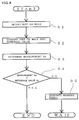
Fig. 2 is a flowchart showing a method of evaluating the degree of
adhesion of adherents according to the first embodiment of the present
invention.
Fig. 3 is a partial cross sectional view of an evaluation apparatus
evaluating the degree of adhesion of adherents according to a second
embodiment of the present invention, showing that a CCD (charge coupled
device) camera of the apparatus takes a picture of a certain area of a mold.
Fig. 4 is a flowchart showing a method of evaluating the degree of
adhesion of adherents according to the second embodiment of the present
invention.
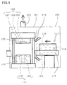
Fig. 5 is a schematic front view of a surface treatment apparatus for
a mold surface according to a third embodiment of the present invention,
showing that the surface treatment apparatus is incorporated in a resin-sealing
apparatus.
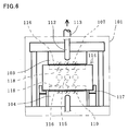
Fig. 6 is a schematic side view of the surface treatment apparatus in
Fig. 5 showing that the apparatus irradiates a mold surface with excimer
ultraviolet radiation.
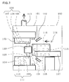
Fig. 7 is a schematic front view of a surface treatment apparatus for
a mold surface according to a forth embodiment of the present invention,
showing that the apparatus is incorporated in a resin-sealing apparatus.
Fig. 8 is a schematic front view of a surface treatment apparatus for
a mold surface according to a fifth embodiment of the present invention,
showing that the apparatus is incorporated in a resin-sealing apparatus to
perform surface treatment
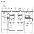
Fig. 9 is a schematic front view of a resin-sealing apparatus having a
cleaning apparatus attached thereto according to a sixth embodiment of the
present invention.
Fig. 10 is a schematic side view of the resin-sealing apparatus shown
in Fig. 9, showing that the cleaning apparatus cleans the surface of a mold
with excimer radiation.
Fig. 11 illustrates an effect of the cleaning apparatus of the sixth
embodiment of the present invention as compared with a conventional
cleaning apparatus using ultraviolet radiation from a low-voltage mercury
lamp.
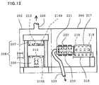
Fig. 12 is a schematic front view showing main portions of a resin-sealing
apparatus having a cleaning apparatus attached thereto, according
to a seventh embodiment of the present invention.
DESCRIPTION OF THE PREFERRED EMBODIMENTS
First Embodiment
With reference to Figs. 1 and 2, an apparatus and a method for
evaluating the degree of adhesion of adherents to the mold surface are
described. According to this embodiment, a mold used for molding resin is
described. Specifically, a mold is described that is used for a resin-sealing
apparatus for sealing electronic components mounted on a leadframe with
resin. Here, as an example of adherents to the mold surface, dirt sticking
to the mold surface is described.
Fig. 1 is a partial cross sectional view of the evaluation apparatus
evaluating the degree of adhesion of adherents according to this
embodiment, showing that an optical sensor of the apparatus emits
radiation and detects reflected radiation of the emitted radiation. Fig. 2 is
a flowchart showing a method of evaluating the degree of adhesion of
adherents according to this embodiment.
Referring to Fig. 1, a mold used for sealing with resin is constituted
of a lower mold 1 and an upper mold 2 placed opposite to this lower mold 1.
Lower mold 1 has a pot 3 formed of a cylindrical space. A substantially
columnar plunger 4 is provided in pot 3 to be movable up-and-down.
Further, a lower cavity 5 is provided to lower mold 1 that is a space where
melted resin is injected. A recess 6 around lower cavity 5 receives a
leadframe placed therein.
Upper mold 2 has a cull 7 placed substantially opposite to pot 3 for
holding melted resin. A resin channel 8 where melted resin flows and an
upper cavity 9 where the melted resin is injected are provided to
successively communicate with cull 7.
A sensor unit 10 is provided between lower mold 1 and upper mold 2
that is secured to an arm 11 and capable of moving forward/backward.
Sensor unit 10 is constituted of a holder 12, a lower sensor 13 attached to the
bottom of holder 12 at a predetermined distance from a surface (mold
surface) of lower mold 1 and an upper sensor 14 attached to the top of holder
12 at a predetermined distance from the mold surface of upper mold 2.
Lower sensor 13 is an optical sensor having a light-emitting unit
emitting radiation 15 and a light-receiving unit receiving reflected radiation
16 that is the reflected radiation of radiation 15 from the mold surface of
lower cavity 5. Similarly, upper sensor 14 is an optical sensor having a
light-emitting unit emitting radiation 17 and a light-receiving unit receiving
reflected radiation 18 that is the reflected radiation of radiation 17 from the
mold surface of cavity 9. Lower sensor 13 and upper sensor 14 convert
respective intensities of reflected radiation 16 and reflected radiation 18
that are detected optical data into predetermined detection signals (voltages
for example) respectively, and supply those respective detection signals to
an operation unit 20 via a signal line 19. It is noted that these lower sensor
13 and upper sensor 14 are optical sensors using infrared radiation, laser or
the like, other than visible radiation.
Operation unit 20 constituted of an A/D converter for example
individually calculates, based on respective detection signals supplied from
lower sensor 13 and upper sensor 14, respective measurements indicative of
the degree of adhesion of adherents to the mold surface of lower mold 1 and
of adherents to the mold surface of upper mold 2. A comparator unit 21
compares respective measurements indicative of the degree of adhesion for
lower mold 1 and upper mold 2 that are provided from operation unit 20
with a predetermined reference value. If the measurements satisfy a
predetermined condition for the reference value, the comparator transmits a
predetermined warning signal via a signal line 22. Operation unit 20
treats a value, which has been calculated based on a measurement as
required, as a new measurement. Comparator unit 21 compares the new
measurement with the reference value. If the new measurement satisfies a
predetermined condition for the reference value, a predetermined warning
signal is transmitted.
According to this embodiment, an operation of the evaluation
apparatus evaluating the degree of adhesion is described with reference to
Figs. 1 and 2. As shown in Fig. 1, sensor unit 10 is allowed to enter
between lower mold 1 and upper mold 2. In step S1 of Fig. 2, the degree of
adhesion of adherents, namely dirt, to the mold surface is detected.
Specifically, lower sensor 13 and upper sensor 14 in Fig. 1 emit radiation 15
and radiation 17 respectively toward respective mold surfaces of lower
cavity 5 and upper cavity 9. Further, lower sensor 13 and upper sensor 14
respectively receive reflected radiation 16 and reflected radiation 18
reflected from respective mold surfaces of lower cavity 5 and upper cavity 9,
use reflected radiation 16 and reflected radiation 18 as optical data, and
convert respective intensities of radiation 16 and radiation 18 into electrical
detection signals. The detection signals are then transmitted to operation
unit 20. The greater the degree of dirtiness on the mold surfaces is, the
lower the intensities of reflected radiation 16 and reflected radiation 18
received by lower sensor 13 and upper sensor 14.
The evaluation apparatus evaluating the degree of adhesion of
adherents according to this embodiment thus detects dirt, if any location of
the mold surface which is prone to dirt sticking thereto is known in advance,
by using this location as a pinpoint.
Next, in step S2, the degree of adhesion of dirt is converted into a
numerical value. Specifically, operation unit 20 in Fig. 1 performs
individual calculation of the degree of adhesion of dirt to respective mold
surfaces of lower mold 1 and upper mold 2 based on the detection signals
supplied respectively from lower sensor 13 and upper sensor 14. Here, the
degree of adhesion is converted into a numerical value through analog-to-digital
conversion of the detection signal representing voltage, for example.
In step S3, based on respective intensities of reflected radiation 16
and reflected radiation 18 as received, measurement VM is then determined
that indicates the degree of adhesion of dirt to each of respective mold
surfaces of lower mold 1 and upper mold 2. Here, the intensity of the
reflected radiation is regarded as a direct measurement. Specifically,
measurement is taken multiple times for the same location prone to dirt
adhering thereto, this location being used as a pinpoint, for example, or
measurement is taken for multiple locations of the mold surface. The
average of a plurality of values resultant from this measurement is
calculated by operation unit 20, and the calculated average is used as
measurement VM. Step S3 may be skipped as required and, if step S3 is
skipped, the numerical value determined in step S2 is used as measurement
VM.
In step S4, operation unit 20 then compares measurement VM
determined in step S3 with a reference value VS representing the intensity
of reflected radiation that is stored in advance. Here, operation unit 20
stores in advance, as a threshold, i.e., reference value Vs, the value of the
intensity of the reflected radiation indicating the greatest degree of dirt that
still has no adverse effect on the molding operation, namely, the intensity of
reflected radiation indicating the degree of adhesion immediately before
occurrence of molding failure.
In step S4, comparator unit 21 compares measurement VM with
reference value VS. If relation: measurement VM > reference value VS is
satisfied for both of lower mold 1 and upper mold 2, which means that
respective intensities of reflected radiation 16 and reflected radiation 18 are
sufficiently high and accordingly comparator unit 21 determines that the
degree of adhesion of dirt to the mold surface is smaller than the reference.
After the evaluation of the degree of adhesion is completed, resin-molding
operation is continued as required.
If relation: measurement VM ≤ reference value VS is satisfied for at
least one of lower mold 1 and upper mold 2, that is, if measurement VM is
equal to or smaller than reference value VS, at least one of the intensities of
reflected radiation 16 and reflected radiation 18 is not great enough. It is
accordingly determined that the degree of adhesion of dirt to the mold
surface is equal to or greater than the reference and the process proceeds to
step S5.
It is noted that the degree of adhesion of dirt may be determined
based on relations VM ≥ VS and VM < VS.
In step S5, comparator unit 21 generates and outputs a warning
signal to signal line 22. A control unit (not shown) which receives this
warning signal stops the resin-molding operation and generates a signal for
starting cleaning. Accordingly, a cleaner (not shown) starts cleaning. The
evaluation apparatus evaluating the degree of adhesion is on standby until
the cleaning is completed. After the cleaning, the evaluation apparatus has
to evaluate again the degree of adhesion of dirt and thus returns to the
operation in step S1 of Fig. 2.
As discussed above, the evaluation apparatus of this embodiment
compares measurement VM indicating the degree of adhesion of dirt that is
calculated according to optical data of the mold surface with predetermined
reference value VS to evaluate the degree of adhesion of dirt and generates a
warning signal if cleaning is necessary. The degree of adhesion of dirt is
thus evaluated quantitatively without the possibility of variation in
evaluation due to subjective evaluation by an operator in charge.
The warning signal indicates an appropriate timing for cleaning and
thus the efficiency of the resin-molding operation is enhanced, the resin-molding
operation is automated, and the yield is improved.
Moreover, as the measurement to be compared with the reference
value, not only measurements based on the intensity of reflected radiation
detected at a plurality of locations on the mold surface, but also
measurements detected at one location may be used. Accordingly,
evaluation may be made of the degree of adhesion of dirt not only on the
entire mold surface but also at any pinpoint which is particularly prone to
dirt adhering thereto.
A modification of the evaluation apparatus of this embodiment is
described below. According to the discussion above, respective intensities
of reflected radiation 16 and reflected radiation 18 that are calculated by
operation unit 20 based on detection signals respectively generated by lower
sensor 13 and upper sensor 14 are used directly as measurement VM and
reference value VS. A similar effect to that achieved by the evaluation
apparatus of the above-discussed embodiment is obtained by the evaluation
apparatus of the modification as described below.
For the intensity of reflected radiation that is calculated by
operation unit 20, a value of ratio RM with respect to a predetermined initial
value, 100, is determined and, this value of ratio RM is compared with a
predetermined value of ratio RTH. The initial value is calculated by
operation unit 20, based on respective detection signals generated by lower
sensor 13 and upper sensor 14 for the mold surface before resin-molding.
Here, the initial value indicates the intensity of each of reflected radiation
16 and reflected radiation 18 when radiation is reflected from the plating
itself of the mold, namely the intensity of reference reflected radiation.
Accordingly, the value of ratio RM calculated by operation unit 20 is the
value of ratio between the intensity of each of reflected radiation 16 and
reflected radiation 18 as measured and the intensity of the reference
reflected radiation that is reflection from the plating itself of the mold, and
this ratio is represented by percentage with respect to the intensity of the
reference reflected radiation of 100.
The evaluation apparatus of this modification then compares in step
S4 the calculated value of ratio RM with predetermined value of ratio RTH by
comparator unit 21 of Fig. 1. Here, predetermined value of ratio RTH is
determined by experiment in advance. If the intensity of each of reflected
radiation 16 and reflected radiation 18 that is measured with respect to 100
of the intensity of the reference reflected radiation by experiment is at least
95 for example, there is no particular problem in terms of the quality of
molded products produced through resin-molding by lower mold 1 and upper
mold 2. In this case, the predetermined value of ratio RTH is 95 %.
In step S4, comparator unit 21 compares the calculated value of ratio
RM with the predetermined value of ratio RTH. If a relation RM ≥ RTH is
satisfied for both of lower mold 1 and upper mold 2, in other words, if a
relation RM ≥ 95% is satisfied, the intensity of each of reflected radiation 16
and reflected radiation 18 is sufficiently large. Then, operation unit 20
determines that the degree of adhesion of dirt to the mold surface is smaller
than the reference. Then, evaluation of the degree of adhesion by the
evaluation apparatus is completed. As required, resin-molding operation is
continued.
In step S4, if a relation RM < RTH is satisfied for at least one of lower
mold 1 and upper mold 2, i.e., a relation RM < 95% is satisfied, the intensity
of at least one of reflected radiation 16 and reflected radiation 18 is not
sufficiently large. Accordingly, the degree of dirt to the mold surface is at
least the reference. After the operation in step S5 by the evaluation
apparatus, the operation is carried out by the evaluation apparatus as
described above.
According to the description above, lower sensor 13 and upper sensor
14 simultaneously detect the degree of adhesion of dirt to respective mold
surfaces of lower mold 1 and upper mold 2. Alternatively, the evaluation
apparatus may have sensor unit 10 with its top or bottom provided with one
optical sensor, sensor unit 10 being inverted by arm 11, and the degree of
adhesion of dirt to respective mold surfaces of lower mold 1 and upper mold
2 being detected successively. Such an evaluation apparatus also achieves
an effect similar to that of the evaluation apparatus of the above-discussed
embodiment.
Further, although the evaluation apparatus of this embodiment
converts the degree of adhesion of dirt into a numerical value in step S2,
steps S2 and S3 may be skipped and the degree of adhesion of dirt may be
evaluated without operation unit 20. In this case, comparator unit 21
directly compares in step S4 measurements of respective detection signals
from lower sensor 13 and upper sensor 14 with a reference value (e.g.
voltage) stored in advance. Then, if the measurement according to one of
reflected radiation 16 and reflected radiation 18 is equal to or smaller than
the equal value, it is determined that the degree of adhesion of dirt to the
mold surface is equal to or greater than the reference and the process
proceeds to step S5.
Moreover, lower sensor 13 and upper sensor 14 may be attached to
such a transport mechanism as loader/unloader. In this case, the degree of
adhesion of dirt is evaluated for each resin-molding operation as required, so
that in-line monitoring of the dirt of the mold is possible. Then, even if dirt
unexpectedly adheres to the mold, the dirt is appropriately found and the
degree of dirtiness is accurately evaluated. A warning signal is generated
depending on the degree of dirtiness so as to prevent defective products from
being manufactured.
Second Embodiment
With reference to Figs. 3 and 4, an evaluation apparatus and an
evaluation method for evaluating the degree of adhesion of adherents to the
mold surface according to a second embodiment of the present invention are
described. Fig. 3 is a partial cross sectional view of the evaluation
apparatus of this embodiment showing that a CCD camera takes a picture of
a certain area of a mold. Fig. 4 is a flowchart showing the evaluation
method of this embodiment. Those components of the evaluation
apparatuses of the first embodiment in Fig. 1 and the second embodiment in
Fig. 3 that have the same function are denoted by the same reference
character.
As shown in Fig. 3, the evaluation apparatus of this embodiment has
CCD camera 23 attached to an arm 11, instead of sensor unit 10 of the first
embodiment. CCD camera 23 is inverted by arm 11 to take a picture of any
of a lower cavity 5 and an upper cavity 9. CCD camera 23 is positioned in
the vertical direction so that the entire mold surfaces of lower cavity 5 and
upper cavity 9 are in view of CCD camera 23 and CCD camera 23 is focused
on the mold surfaces.
Two CCD cameras may be attached to arm 11 to face upward and
downward respectively. In this case, respective pictures of the cavities both
can be taken without inverting arm 11.
The evaluation apparatus of this embodiment operates as described
below. As shown in Fig. 3, CCD camera 23 is allowed to enter between a
lower mold 1 and an upper mold 2. In step S1 in Fig. 4, CCD camera 23
takes a picture of the mold surface of the entire bottom of lower cavity 5.
The picture thus taken is optical data, and any portion of the picture that
has a relatively high density corresponds to a part to which dirt adheres.
In step S2, the degree of adhesion of adherents, i.e., dirt, is converted
into a numerical value, based on the image of lower cavity 5. Specifically,
an operation unit 20 in Fig. 3 binarizes the image of lower cavity 5 according
to a predetermined reference level, i.e., threshold of the density. This
threshold is determined in advance by experiment.
In step S3, operation unit 20 calculates a measurement VM which is
a sum of areas each having the density of the binarized image that is equal
to or higher than the threshold, namely a sum of dirty areas.
In step S4, a comparator unit 21 in Fig. 3 compares measurement VM
with a reference value VS which is stored in advance. Reference value VS
relates to the magnitude of dirty areas. Reference value VS is determined
in advance as described below and stored in comparator unit 21 in Fig. 3.
Specifically, as resin-molding operation is repeated, dirty areas gradually
increase, resulting in defective molded products. Here, the sum of dirty
areas immediately before occurrence of any defect in molded products is
determined as reference value VS.
In step S4, if a relation: measurement VM < reference value VS (or VM
≤ VS) is satisfied, the dirty areas are small enough and then the evaluation
apparatus determines that the degree of adhesion of dirt to the mold surface
is smaller than the reference value, and the evaluation of the degree of
adhesion is completed. The resin-molding operation is subsequently
continued as required.
In step S4, if a relation: measurement VM ≥ reference value VS (or VM
> VS) is satisfied, the dirty areas are not small enough and then the
evaluation apparatus determines that the degree of adhesion of dirt to the
mold surface is equal to or greater than the reference value to perform an
operation in step S5. Then, the evaluation apparatus of this embodiment
performs the operation in step S5 similarly to the evaluation apparatus of
the first embodiment.
As discussed above, the evaluation apparatus of this embodiment
generates a warning signal, based on the optical data of the mold surface,
namely image, when dirt adheres to such a degree that requires cleaning, as
the evaluation apparatus of the first embodiment. In this way, the degree
of adhesion of dirt is quantitatively evaluated. Accordingly, the efficiency
of the resin-molding operation is enhanced, the resin-molding operation is
automated and the yield is improved.
The evaluation of the degree of adhesion of dirt is performed based
on the image obtained by taking a picture of the entire mold surface. The
degree of adhesion of dirt to the entire mold surface is thus evaluated in a
short period of time.
Respective evaluation apparatuses of the above-described
embodiments each start cleaning according to a warning signal.
Alternatively, the control unit may generate a warning signal indicating an
abnormal state by lighting a warning lamp, for example. In this case, an
operator in charge stops the resin-molding operation to start cleaning.
The evaluation apparatuses respectively of the first and second
embodiments use, as optical data, the received reflected radiation or the
image obtained by taking the picture to calculate a measurement indicative
of the degree of adhesion of dirt. The optical data may include color
components and then a measurement may be calculated. Specifically, the
evaluation apparatus of the first embodiment may measure the intensity of
the reflected radiation based on color components, and the evaluation
apparatus of the second embodiment may process the density not only on the
basis of monochrome but also on the basis of color contrast. Then,
depending on the type of melted resin which causes dirt, optical data may
include color components so as to more accurately evaluate the degree of
adhesion.
The mold may be cleaned with a brush for example, by means of
ultraviolet radiation or by injecting melamine resin into each cavity.
Each time the resin-molding operation is done or the resin-molding
operation is done a relatively small number of times, sensor unit 10 may be
allowed to enter between lower mold 1 and upper mold 2 to evaluate the
degree of adhesion. In this case, the degree of adhesion of dirt to the mold
surface is monitored substantially in the line. Then, even if dirt adheres to
the mold surface unexpectedly, the dirt is appropriately found and the
degree of adhesion is accurately evaluated. Depending on the degree of
dirtiness, a warning signal may be generated to prevent defective products
from being manufactured, for example.
Moreover, it may be determined by experiment how many times the
resin-molding operation is done before the degree of adhesion of dirt reaches
or exceeds the reference value. Then, in the stage immediately before the
determined number is reached, the degree of adhesion may be evaluated, for
example, each time the resin-molding operation is carried out. In this case,
the time required for evaluation of the degree of adhesion is shortened to
increase the efficiency of the entire resin-sealing operation.
Regarding respective evaluation apparatuses of the embodiments
discussed above, dirt is referred to as an example of matters adhering to the
mold surface. Alternatively, to any material composing a layer formed on
the mold surface for the purpose of improving the releasability, i.e., a release
agent, the evaluation apparatus of each embodiment of the present
invention may be applied to evaluate the degree of adhesion of the release
agent. In this case, the release agent gradually peels off from the mold
surface as the resin-molding operation is repeated, resulting in failure in
molding. Then, in order to evaluate the degree of adhesion of the release
agent by means of the intensity of reflected radiation, the degree is
determined on a basis as described below, since the intensity of the reflected
radiation increases as the release agent peels off.
More specifically, comparator unit 21 compares measurement VM
with predetermined reference value Vs. If a relation, measurement VM <
reference value VS is satisfied, the evaluation apparatus determines that the
intensity of each of reflected radiation 16 and reflected radiation 18 is
sufficiently small. Then, the degree of adhesion of the release agent to the
mold surface is greater than the reference, which means a good releasability
of a molded product from a mold is secured and there is no problem
accordingly. If there is a relation, measurement VM ≥ reference value VS,
any of reflected radiation 16 and reflected radiation 18 has an intensity
which is not small enough. The degree of adhesion of the release agent to
the mold surface is equal to or smaller than the reference value, and the
releasability of the molded product from the mold is deteriorated.
Comparator unit 21 accordingly generates a warning signal.
The evaluation as described above is performed of the degree of
adhesion of adherents or dirt to a mold employed for a resin-sealing
apparatus. Alternatively, the present invention is applicable to other
molds for molding resin including molds for injection-molding.
Further, the present invention is not limited to the evaluation
apparatuses respectively of the above-discussed embodiments. The
characteristic structure of the present invention may be applied by being
modified or selected arbitrarily and properly as required to the extent that
such a modification or selection falls within the scope of the invention.
Third Embodiment
With reference to Figs. 5 and 6, a surface treatment apparatus for a
mold surface according to a third embodiment of the present invention is
described, in connection with a mold used for sealing electronic components
with resin, as an example of molds used for molding resin. Fig. 5 is a
schematic front view of the surface treatment apparatus of this embodiment
showing that the apparatus is incorporated in a resin-sealing apparatus.
Fig. 6 is a schematic side view of the surface treatment apparatus in Fig. 5
showing that the apparatus irradiates the mold surface with excimer
ultraviolet radiation.
Referring to Fig. 5, a mold unit 101 is used for sealing with resin and
a waiting unit 102 is coupled to mold unit 101 to serve as a place where a
lamp unit described hereinbelow waits. In mold unit 101, an upper mold
103 and a lower mold 104 are placed to face each other for resin-sealing.
Upper mold 103 is fixed and has a cull 105 as well as a runner 106 and a
cavity 107 communicating successively with cull 105. Cull 105, runner 106
and cavity 107 compose a resin-flowing portion 108 of upper mold 103.
Lower mold 104 is movable and has a pot 109 placed opposite to cull 105.
Lower mold 104 also has a cavity 110 placed opposite to cavity 107. Pot 109
and cavity 110 compose a resin-flowing portion 111 of lower mold 104. A
nozzle 112 is connected via a valve to a gas supply source (both are not
shown) to serve as a jet mechanism emitting a jet of a predetermined gas as
required. The emitted jet of gas is any gas, except for oxygen, having a
property of suppressing attenuation of excimer ultraviolet radiation, a
nitrogen gas, for example. An exhaust pipe 113 is connected via a valve to
a suction pump (both are not shown) to discharge the gas within mold unit
101 to the outside.
A lamp unit 114 serves as an irradiation mechanism irradiating
respective surfaces of upper mold 103 and lower mold 104 with excimer
ultraviolet radiation. An excimer lamp 115 is mounted within lamp unit
114 to generate excimer ultraviolet radiation of 172 nm in wavelength by
dielectric barrier discharge with xenon (Xe) used as a discharge gas. A
translucent window 116 provided on each of the upper and lower sides of
lamp unit 114 is made of synthetic quartz glass for example and serves as a
window for irradiation. For the purpose of preventing decrease of the
illuminance of the excimer ultraviolet radiation on the mold surface, the
distance between translucent window 116 and each mold surface is
preferably as short as possible. A rail 117 is a transport mechanism for
moving lamp unit 114, and lamp unit 114 driven by a motor (not shown) is
moved horizontally along rail 117.
An operation of the surface treatment apparatus for the mold surface
according to this embodiment is now described with reference to Figs. 5 and
6. On respective resin-flowing portions 108 and 111 of upper mold 103 and
lower mold 104 heated to a predetermined molding temperature (e.g. 180°C)
in advance, a mold release layer containing a specific component as a mold
release agent is formed on the mold surface in advance. On the surface of
the mold release layer, a component which deteriorates the releasability is
generated through the molding.
Referring to Fig. 5, lamp unit 114 is moved from waiting unit 102
along rail 117 and stopped at a predetermined position which allows desired
regions on the mold surfaces of upper mold 103 and lower mold 104 to be
irradiated uniformly with the excimer ultraviolet radiation passed through
translucent window 116. Moreover, a jet of nitrogen gas is emitted by
nozzle 112 to the regions close to the mold surfaces of upper mold 103 and
lower mold 104. Accordingly, the regions close to the mold surfaces are in
an atmosphere of low-oxygen-concentration.
Then, a predetermined high-frequency voltage is applied to excimer
lamp 115. Accordingly, as shown in Fig. 6, excimer lamp 115 generates
excimer ultraviolet radiation 118 having a predetermined center frequency
(e.g. 172 nm). Lamp unit 114 thus irradiates respective mold surfaces of
upper mold 103 and lower mold 104, i.e., respective mold surfaces of resin-flowing
portions 108 and 111 shown in Fig. 5 with excimer ultraviolet
radiation 118 through translucent window 116. The excimer ultraviolet
radiation 118 is called VUV (Vacuum Ultraviolet), having a wavelength of
an extremely narrow range with its center at the center frequency, i.e.,
single peak wavelength, and having a characteristic of a high photon
energy.
Excimer ultraviolet radiation 118 is emitted under a condition that
the energy of excimer ultraviolet radiation 118 has a value to the extent that
the mold release layer does not peel off from the mold surface when the mold
surface is irradiated for a certain period of time, and this value is
determined in advance. In addition, preferably this energy has a value to
the extent that the state of the mold surface returns to a state immediately
after the mold release layer is formed thereon, namely the initial state,
when the mold surface is irradiated for a certain period of time. Excimer
ultraviolet radiation 118 having such an energy is emitted to the mold
surface to allow the state of the mold surface to become close to the initial
state, or return to the initial state, depending on irradiation conditions.
The mold surface is thus irradiated with excimer ultraviolet radiation 118
for a certain period of time and then the surface treatment for the mold
surface is completed.
Here, a detailed description is given below, regarding the action of
excimer ultraviolet radiation 118. By the energy of excimer ultraviolet
radiation 118, ozone (O3) and active oxygen are generated from oxygen
present within mold unit 101. Of the generated ozone and active oxygen,
the active oxygen in particular causes the surface of the mold release layer
to be activated. Then, the state of the mold surface becomes close to the
initial state or returns to the initial state depending on irradiation
conditions. The gas within mold unit 101 contains ozone which is
hazardous to humans and causes metal and polymeric materials to be
degraded or corroded. Then, this gas is discharged to the outside of the
resin sealing apparatus through exhaust pipe 113.
By the surface treatment apparatus of this embodiment, the space
near the mold surface, i.e., the space between translucent window 116 and
the mold surface, is in an atmosphere of low-oxygen-concentration as a jet of
nitrogen gas is emitted thereinto that has a property of suppressing
attenuation of excimer ultraviolet radiation. Attenuation of excimer
ultraviolet radiation 118 due to oxygen is thus suppressed. Since there is
no decrease of the efficiency of generating ozone and active oxygen, the
efficiency of activating the mold surface as the mold surface becomes close to
the initial state is maintained. Further, excimer ultraviolet radiation 118
is unlikely to attenuate. Then, even if the mold surface has depressed and
protruded portions and is thus uneven, the surface of the entire mold release
layer including the mold release layer on the depressed portion of the mold
surface is uniformly activated.
Then, emission of the jet of nitrogen gas by nozzle 112 is stopped,
and lamp unit 114 is moved along rail 117 to waiting unit 102 shown in Fig.
5. After this, a substrate with electronic components mounted thereon is
placed on lower mold 104, upper mold 103 and lower mold 104 are clamped
together, melted resin (not shown) is injected from pot 109 into cavities 107
and 110 by being passed successively through cull 105 and runner 106, and
the melted resin is cured to produce cured resin.
Then, upper mold 103 and lower mold 104 are opened to take out a
molded product (not shown) formed of the substrate and the cured resin.
Then, resin-sealing of electronic components is completed.
Next, lamp unit 114 is moved from waiting unit 102 to a
predetermined location, and a jet of nitrogen gas is emitted to portions close
to the mold surfaces of the upper mold 103 and lower mold 104. As shown
in Fig. 6, lamp unit 114 emits excimer ultraviolet radiation 118 to respective
mold surfaces of upper mold 103 and lower mold 104. The surface
treatment of the mold surfaces and resin-sealing of electronic components
are thereafter repeated.
As discussed above, the surface treatment apparatus of this
embodiment performs the surface treatment of the mold surfaces, between
resin-sealing operations of electronic components, by irradiating respective
mold surfaces of upper mold 103 and lower mold 104 with excimer
ultraviolet radiation 118 having a single peak wavelength and a high
photon energy. Then, the surfaces of the mold release layers on the mold
surfaces are activated, the state of the mold surfaces becomes close to the
initial state or returns to the initial state depending on irradiation
conditions. In resin-sealing of electronic components, the releasability of
cured resin from the mold surface is thus ensured to prevent adherents from
being deposited on the mold surface. In addition, cleaning with a brush for
example is unnecessary, which allows resin-sealing to be carried out
successively. Moreover, the efficiency of generating ozone and active
oxygen is improved. Even if the mold surface is uneven, the surface of the
mold release layer on the mold surface is uniformly activated.
According to the description above of the surface treatment
apparatus of this embodiment, after lamp unit 114 is stopped at a
predetermined position, excimer lamp 115 is turned on to emit excimer
ultraviolet radiation 118. Alternatively, with excimer lamp 115 turned on,
the mold surfaces may be irradiated with excimer ultraviolet radiation 118
while lamp unit 114 is moved. In this case, not only the energy of excimer
ultraviolet radiation 118 but also the moving speed of lamp unit 114 may
preferably be considered to determine the irradiation conditions for the mold
release layer. In addition, one or a plurality of excimer lamps 115 may
preferably be provided that are perpendicular to the side of the apparatus
seen in Fig. 5.
When the surface treatment apparatus of this embodiment is used,
the mold surfaces are irradiated each time the resin-sealing operation is
performed. Alternatively, a relation between the number of times the
resin-sealing operation is successively done, the state of the mold surfaces
and the releasability may be evaluated in advance and then the mold
surfaces may be irradiated after the resin-sealing operation is done a
predetermined number of times according to the evaluation. Lamp unit
114 thus operates a minimum number of times as required, which enhances
the working efficiency of resin-sealing.
Fourth Embodiment
With reference to Fig. 7, a fourth embodiment of the present
invention is described. Fig. 7 is a schematic front view of a surface
treatment apparatus for a mold surface of this embodiment showing that the
apparatus is incorporated in a resin-sealing apparatus. This embodiment
has a characteristic that the surface treatment apparatus includes an
evaluation mechanism which optically detects the state of the mold surface
to determine whether irradiation is necessary or not.
Referring to Fig. 7, a sensor 119 is the evaluation mechanism which
emits radiation 120 in both of the upward and downward directions, detects
reflected radiation 121 which is radiation 120 reflected from each mold
surface, calculates the ratio of reflected radiation 121 to emitted radiation
120, i.e., reflectance, and compares the calculated reflectance with a
predetermined reference value. Sensor 119 may be an optical non-contact
sensor using, for example, visible radiation, infrared radiation or laser.
An operation of the surface treatment apparatus according to this
embodiment is described with reference to Fig. 7. As in the surface
treatment apparatus of the third embodiment, a lamp unit 114 is moved,
and a jet of nitrogen gas is emitted to regions close to respective mold
surfaces of an upper mold 103 and a lower mold 104 by a nozzle 112.
Sensor 119 then reaches the position facing cavities 107 and 110 to
emit radiation 120 in both of the upward and downward directions and then
detect reflected radiation 121 which is radiation 120 reflected from
respective surfaces of cavities 107 and 110. Further, sensor 119 calculates
the reflectance to compare the calculated reflectance with a predetermined
reference value. Respective operations of detection of reflected radiation
121, calculation of the reflectance and comparison between the reflectance
and the reference value may be shared by the sensor body and a calculating
unit.
If the calculated reflectance is equal to or higher than the reference
value, for example, sensor 119 determines that there is only a slight change
in the state of the mold surface relative to an initial state and thus generates
no signal which turns on an excimer lamp 115. Accordingly, lamp unit 114
returns to a waiting unit 102 without emitting radiation, upper mold 103
and lower mold 104 are clamped together and normal resin-sealing
operation is carried out.
On the other hand, if the calculated reflectance is lower than the
reference value, sensor 119 determines that the state of the mold surface
changes relative to the initial state and generates a signal for turning on
excimer lamp 115. According to this signal, lamp unit 114 irradiates the
mold surface with radiation under predetermined conditions for irradiation
and thereafter returns to waiting unit 102. Then, normal resin-sealing
operation is performed.
As discussed above, the surface treatment apparatus of this
embodiment determines, based on the result of optical evaluation of the
state of the mold surface, whether or not the mold surface is to be irradiated
with the radiation. Accordingly, an effect similar to that achieved by the
surface treatment apparatus of the third embodiment is obtained. In
addition, since the radiation is emitted to the mold surface as required so as
to cause the mold surface to return to the initial state, the working efficiency
of the resin-sealing is further improved.
According to the description of the surface treatment apparatus of
this embodiment, radiation is emitted to the mold surface with lamp unit
114 being stopped. Alternatively, the radiation may be emitted to the mold
surface while lamp unit 114 is moving.
It is determined whether or not the mold surface is to be irradiated,
according to the result of evaluation by sensor 119. Alternatively, based on
the result of evaluation by sensor, such conditions for irradiation as the
period of time for irradiation while the lamp unit is stationary, the moving
speed when the radiation is emitted while the lamp unit is moving, the
distance for irradiation and the illuminance, for example may be determined.
Specifically, if it is determined by the evaluation that the surface of a mold
release layer considerably changes relative to the initial state, the
irradiation time may be extended to allow the surface of the mold release
layer to return to the initial state.
Sensor 119 may evaluate the state of the mold surface by calculating
respective reflectances of a plurality of points to find any point where the
state of the mold surface changes to the greatest degree and accordingly
makes an evaluation based on that point, or calculates the average of the
reflectances and makes an evaluation based on the average. Alternatively,
the reflectance of a point of each of cavities 107 and 110 that is close to a
runner 106 may be calculated by using that point as a pinpoint, in order to
evaluate the state of the mold surface.
In the surface treatment apparatus of this embodiment, sensor 119
calculates the reflectance and compares the reflectance with the reference
value. Alternatively, the state of the mold surface may be evaluated based
on image data obtained by taking a picture of a certain region. For example,
sensor 119 used here may include a CCD camera and an image processing
unit to binarize the obtained image with a predetermined threshold and
compare the area of a region of a high density with a reference value.
Fifth Embodiment
With reference to Fig. 8, a fifth embodiment of the present invention
is described. Fig. 8 is a schematic front view of a surface treatment
apparatus for a mold surface according to this embodiment showing that the
apparatus is included in a resin-sealing apparatus to carry out surface
treatment. This embodiment has a characteristic that the surface
treatment apparatus for the mold surface has a mechanism of heating and
supplying gas.
Referring to Fig. 8, nozzles 122 are provided to constitute a jetting
mechanism connected via a gas pipe 123 and a valve 124 to a gas source 125
and placed, for example, to extend from respective corners of a lamp unit 114
toward respective centers of the top surface and the bottom surface of the
lamp unit. From this nozzle 122, a jet of gas having a property of
suppressing attenuation of excimer ultraviolet radiation, nitrogen gas 126
for example, is emitted to the regions near respective mold surfaces of an
upper mold 103 and a lower mold 104. A heater is a heating mechanism
provided on gas pipe 123 between gas source 125 and valve 124 to heat
nitrogen gas 126 to a predetermined temperature (e.g. 180°C equal to
molding temperature). A cooling pipe 128 is a cooling mechanism placed
around a translucent window 116 of lamp unit 114 to cool translucent
window 116 to a predetermined temperature (e.g. 120°C) or less by
circulating such fluid coolant like water.
If it is possible to heat emitted jet of nitrogen gas 126 to a
predetermined temperature, heater 127 may be provided on gas pipe 123
near each nozzle 122. In this case, valve 124 may be attached closer to
nozzle 122 relative to heater 127.
Instead of cooling pipe 128, such a cooling mechanism as Peltier
device may be provided near translucent window 116.
The surface treatment apparatus of this embodiment provides
advantages as described below. First, the effect of activating the surface of
a mold release layer is maintained, since the temperature of the mold
surface is kept constant. In other words, nitrogen gas 126 heated to a
predetermined temperature by heater 127 is jetted to the regions near
respective mold surfaces of upper mold 103 and lower mold 104 to allow the
temperature of the mold surface to be kept at a molding temperature. Here,
the effect of activating the surface of the mold release layer by ozone and
active oxygen generated by excimer ultraviolet radiation is reduced if the
temperature of the mold surface decreases. Then, as the temperature of the
mold surface is kept at the molding temperature, the effect of activating the
surface of the mold release layer is maintained.
Second, the illuminance of excimer ultraviolet radiation on the mold
surface is maintained. Specifically, translucent window 116 is cooled by
cooling pipe 128. As translucent window 116 made of synthetic quartz
glass has a property that the transmission factor decreases as the
temperature increases. Then, the transmission factor of translucent
window 116 is maintained by cooling translucent window 116 and thus the
illuminance of the excimer ultraviolet radiation on the mold surface is
maintained.
Regarding the surface treatment apparatus of each of the above-discussed
embodiments, nozzle 122, lamp unit 114 (and sensor 119) may be
attached to a transport mechanism for loading a substrate and unloading a
molded product, i.e., a loader and an unloader. Then, in any of the
situations prior to loading of a substrate and subsequent to unloading of a
molded product, the surface treatment of the mold surface is readily
performed. The mold surface is thus returned to the initial state in a
shorter period of time and at a higher frequency.
Both of the upper and lower molds 103 and 104 undergo the surface
treatment. Alternatively, the mold surface of any one of these molds may
undergo the surface treatment.
Nozzle 122, lamp unit 114 (and sensor 119) may be provided for the
surface of only one of the upper and lower molds to emit a jet of gas to this
mold surface, emit excimer ultraviolet radiation and evaluate the state of
the mold surface. In this case, nozzle 122, lamp unit 114 (and sensor 119)
may be inverted as required.
The discharge gas composed of xenon (Xe) only is used here to
generate excimer ultraviolet radiation. Alternatively, any discharge gas
containing at least one of elements F, Ar, Kr, Xe for example may be used.
In this case, excimer ultraviolet radiation having a single peak wavelength
except for the wavelength of 172 nm, particularly a single peak wavelength
shorter than 172 nm, is obtained as well.
According to the description above, the mold release layer is formed
with the intention of using melted resin containing an ample amount of
mold release agent for ensuring the releasability. Alternatively, the layer
formed on the mold surface may be an organic thin film, plating layer or the
like for ensuring the releasability. In addition, the present invention may
be applied to ensure the releasability between cured resin and a layer
formed on the mold surface without the purpose of ensuring the
releasability.
The mold described above is used for sealing electronic components
with resin. Alternatively, the present invention is applicable to other
molds for molding resin.
Sixth Embodiment
With reference to Figs. 9-11, a sixth embodiment of the present
invention is described regarding cleaning of a mold used for a resin-sealing
apparatus. Fig. 9 is a schematic front view of a resin-sealing apparatus of
this embodiment having a cleaning apparatus attached thereto.
Referring to Fig. 9, a loading/unloading unit 201 is provided near the
resin-sealing apparatus for loading a circuit board with electronic
components mounted thereon into the resin-sealing apparatus and
unloading a resin-sealed package therefrom. Further, a molding unit 202
is provided near the resin-sealing apparatus for sealing the circuit board
having electronic components mounted thereon with resin.
Loading/unloading unit 201 and molding unit 202 constitute an elementary
unit 203 which is a minimum component of the resin-sealing apparatus. A
cleaning unit 204 is further provided near the resin-sealing apparatus that
has a cleaning apparatus for cleaning a mold (described later) used for the
resin-sealing apparatus.
The resin-sealing apparatus includes clamping plates 205A and
205B for securing a movable lower mold 206 and a stationary upper mold
207 respectively. The resin-sealing apparatus includes this movable lower
mold 206 secured to the lower clamping plate 205A which is provided to
freely move up and down as well as stationary upper mold 207 secured to the
upper clamping plate 205B. Movable lower mold 206 and stationary upper
mold 207 compose a mold 208 for sealing with resin. The resin-sealing
apparatus further includes a tie-bar 209 connected to the main body via
clamping plates 205A and 205B. The resin-sealing apparatus includes a
bottom base 210 constituting the lowest part of the body of molding unit 202.
The resin-sealing apparatus includes a mold open/close mechanism 211
which closes or opens mold 208 by moving clamping plate 205A upward or
downward or allowing movable lower mold 206 to ascend or descend.
Further, the resin-sealing apparatus includes a pot 212 which is a
cylindrical space and a plunger 213 movable up and down in pot 212 that
are provided to movable lower mold 206. The resin-sealing apparatus
includes cavities 214A and 214B provided respectively to movable lower
mold 206 and stationary upper mold 207 that are each a space into which
melted resin is injected. The resin-sealing apparatus includes a cull 215
which is placed to face pot 212 of movable lower mold 206 and is a space
provided in stationary upper mold 207.
Moreover, the resin-sealing apparatus includes a guide rail 216
secured to loading/unloading unit 201 and cleaning unit 204 to pass each
molding unit 202. The resin-sealing apparatus includes a cleaner unit 217
for cleaning the mold surface of mold 208 by emitting excimer radiation to
the mold surface of mold 208. The resin-sealing apparatus includes, in the
cleaner unit 217, one or a plurality of (three in the resin-sealing apparatus
of this embodiment) excimer lamps 218 depending on the size of an object to
be cleaned, the excimer lamp generating excimer radiation. Within the
excimer lamp 218, discharge gas containing at least one of the elements F,
Ar, Kr and Xe is enclosed, for example, xenon (Xe) is enclosed. The resin-sealing
apparatus further includes a translucent window 219 fit in an
opening of each of the top and bottom surfaces of cleaner unit 217 and made
of a material which allows excimer radiation to pass, quartz glass, for
example. In addition, the resin-sealing apparatus includes an exhaust pipe
220 provided to on the top surface of each molding unit 202 and connected to
an exhaust mechanism (not shown).
An operation of the cleaning apparatus according to this
embodiment is now described with reference to Figs. 9-11. Fig. 10 is a
schematic side view of the resin-sealing apparatus shown in Fig. 9 showing
that the cleaning apparatus cleans the surface of the mold with excimer
radiation.
When no resin-molding is performed by mold 208, namely movable
lower mold 206 and stationary upper mold 207 are separated from each
other, cleaner unit 217 is moved along guide rail 216 toward molding unit
202. Cleaner unit 217 is stopped at a position which allows a desired
region of the mold surface of each of movable lower mold 206 and stationary
upper mold 207 to be irradiated uniformly with excimer radiation passed
through translucent window 219. The distance between translucent
window 219 and each mold surface is preferably as small as possible in order
to prevent the intensity of the excimer radiation from decreasing.
A predetermined high-frequency voltage is applied to each of the
three excimer lamps 218. Accordingly, each excimer lamp 218 which uses
xenon (Xe) as discharge gas generates excimer radiation having a center
wavelength (peak) of 172 nm. The excimer radiation is thus emitted
through each translucent window 219 to each of respective mold surfaces of
movable lower mold 206 and stationary upper mold 207. The energy of the
excimer radiation having its wavelength in an extremely small range with
the center frequency at the center, i.e., single peak wavelength, breaks the
chemical bond of any matter adhering to the irradiated mold surface, such
an organic material as resin residue. The firmness of bonding between the
mold surface and the matter adhering to the mold surface is thus lessened.
Irradiation with the excimer radiation is continued. Then, ozone
(O3) and atoms of active oxygen generated by the excimer energy act on the
adhering matter with the lessened firmness of bonding to oxidize, decompose
and accordingly volatilize the adhering matter. The adhering matter is
thus removed from the mold surface. By means of exhaust pipe 220, the
adhering matter removed from the mold surface is discharged to the outside
of the apparatus. As the generated ozone is hazardous to humans, the
atmosphere containing the ozone is also discharged to the outside of the
apparatus by means of exhaust pipe 220. After irradiation with the
excimer radiation is continued for a predetermined time necessary for
cleaning, excimer lamps 218 are turned off.
Through the above-discussed operation, the mold surfaces, i.e.,
respective surfaces of the top part of pot 212 (not shown in Fig. 10), cavities
214A and 214B, cull 215 (not shown in Fig. 10) and a resin passage
communicating with cavity 214A and cull 215 are irradiated with the
excimer radiation having a single peak wavelength, a high energy
conversion efficiency and a high photon energy, particularly having a center
wavelength of 172 nm. Such a matter adhering to the mold surface as
residue of resin is thus removed from the mold surface in a short period of
time.
As cleaner unit 217 having excimer lamps 218 is moved to irradiate
the surface of resin-sealing mold 208 with excimer radiation, mold 208 is
cleaned by cleaner unit 217 incorporated in the resin-sealing apparatus.
The process of cleaning mold 208 is thus automated.
Further, as excimer lamps 218 are illuminated for a predetermined
period of time, reduction of the energy consumption as well as increase of the
life of excimer lamps 218 are achieved.
In addition, as mold 208 is cleaned in non-contact manner, mold 208
is cleaned with its surface receiving no damage.
Fig. 11 illustrates an effect of the cleaning apparatus of this
embodiment as compared with a conventional cleaning apparatus using
ultraviolet radiation from a low-voltage mercury lamp. Dirt on the surface
of mold 208 is detected optically by a sensor and converted into a numerical
value. Here, a cleaning ratio of 100 % refers to the state without adhering
dirt, namely the state in which the color and gloss of plating itself of mold
208 before resin-sealing are detected as they are. Cleaning is regarded as
being completed when it is determined by visual inspection of the surface of
mold 208 that the color and gloss of the mold surface are equivalent to those
of plating itself. It has been confirmed empirically that, if it is determined
by visual inspection that the surface of mold 208 has its color and gloss
identical to those of plating itself, no particular problem occurs in resin
sealing.
Specifically, two molds 208 of the same type are used, and resin-sealing
is performed the same number of times by these molds in order to
cause dirt to stick to respective mold surfaces to the same degree. A sensor
is used to detect the dirt on the surface of mold 208 and a relative value of
dirt with respect to the cleaning ratio of 100 % is calculated to use the
resultant relative value as an initial value. This initial value thus
calculated corresponds to the cleaning ratio of 66 %.
Then, one of the two molds 208 having dirt adhering thereto to the
same degree is cleaned according to this embodiment and the other mold is
cleaned by the conventional method. At every two minutes of irradiation
time, i.e., cleaning time, the dirt on the surface of mold 208 is detected by the
sensor to calculate a relative value of the dirt. In any case, the mold
temperature during irradiation is 180°C and the irradiation is done in an
atmosphere.
As shown in Fig. 11, the cleaning ratio increases as cleaning time
passes for both of the cleaning of this embodiment and the conventional
cleaning, and accordingly the dirt is removed step by step. Respective
graphs for cleaning of this embodiment and the conventional cleaning are
both slightly uneven, which could be due to variations of measurement.
From the comparison of the time consumed for completing the
cleaning (cleaning completion time), it is seen that the cleaning completion
time of this embodiment is approximately six minutes while the cleaning
ratio of the conventional cleaning is 92-93 % and substantially reaches
saturation even when twenty minutes have passed. Then, cleaning of this
embodiment is completed in approximately six minutes while the
conventional cleaning does not attain a satisfactory level even when twenty
minutes have passed. The cleaning of this embodiment thus provides an
effect superior to that of the conventional cleaning.
For the cleaning of this embodiment, one excimer lamp is used that
has a lamp power of 20 W and uses xenon (Xe) as discharge gas. The center
wavelength (peak) of generated excimer radiation is 172 nm. A final
distance between the mold surface and the bottom surface of the translucent
window from which the excimer radiation is emitted toward the mold
surface is 4 mm.
For the conventional cleaning, one low-voltage mercury lamp having
a lamp power of 3.0 kW is used. The wavelength of generated ultraviolet
radiation is 254 nm and 185 nm. A final distance between the mold surface
and the surface of a lamp tube from which the ultraviolet radiation is
emitted toward the mold surface is 55 mm.
The difference in lamp power between these two cleaning methods is
due to different principles of irradiation. The difference in distance
between the place from which radiation is emitted and the mold surface is
due to constraints on the apparatuses. However, this difference in the
distance would have almost no influence on the cleaning effect since the
ultraviolet radiation generated by the low-voltage mercury lamp is
extremely unlikely to be absorbed by the air.
The radiant emittance at the place from which the excimer radiation
or ultraviolet radiation is emitted is 15 mW/cm2 for the excimer radiation
and 25 mW/cm2 for the ultraviolet radiation (wavelength 254 nm) from the
low-voltage mercury lamp. This fact means that the excimer radiation and
the ultraviolet radiation have the radiant emittance of the same order and
the excimer radiation having a single peak wavelength has a higher energy
conversion efficiency relative to other radiations.
Seventh Embodiment
Adherents sticking to the mold surface like residue of resin may not
be removed satisfactorily by excimer radiation only, if, for example, sealing
resin is bonded firmly (to the mold surface) or the mold surface has a
complex shape. A cleaning method of a seventh embodiment is applied to
such a case.
The cleaning method of the seventh embodiment is now described
with reference to Fig. 12 regarding cleaning of a mold used for a resin-sealing
apparatus. Fig. 12 is a schematic front view of the resin-sealing
apparatus showing a main portion thereof, the sealing apparatus having a
cleaning apparatus of this embodiment attached thereto.
Referring to Fig. 12, the resin-sealing apparatus includes a cleaning
unit 221 using a brush and a suction tube that are described below.
Cleaning unit 221 is placed adjacently to a cleaner unit 217 using an
excimer lamp 218 and attached to a guide rail 216 to be movable forward
and backward. Metal meshes are mounted respectively on top and bottom
surfaces of cleaning unit 221. The resin-sealing apparatus includes
brushes 222 provided on both of the top and bottom surfaces of cleaning unit
221 having respective leading ends touching respective mold surfaces of a
movable lower mold 206 and a stationary upper mold 207. Further, the
resin-sealing apparatus includes a suction tube 223 provided on any side of
cleaning unit 221 and connected to a suction mechanism (not shown). This
structure allows the atmosphere near both of the top and bottom surfaces of
cleaning unit 221 to be sucked into cleaning unit 221 by suction tube 223.
The cleaning apparatus according to this embodiment including
cleaner unit 217 and cleaning unit 221 operates as detailed below.
With movable lower mold 206 and stationary upper mold 207 being
opened, cleaner unit 217 and cleaning unit 221 are moved along guide rail
216 toward a molding unit 202. Cleaner unit 217 is then stopped at a
position to allow desired regions on respective mold surfaces of movable
lower mold 206 and stationary upper mold 207 to be irradiated uniformly
with excimer radiation passed through translucent windows 219.
In the cleaning apparatus of this embodiment, as the cleaning
apparatus of the sixth embodiment, excimer lamp 218 emits excimer
radiation through respective translucent windows 219 onto respective mold
surfaces of movable lower mold 206 and stationary upper mold 207.
Accordingly, the energy of the excimer radiation lessens the firmness of
bonding between the mold surface and adherents to the mold surface.
Further, the cleaning apparatus of this embodiment continues to
emit, as the cleaning apparatus of the sixth embodiment, the excimer
radiation to oxidize, decompose and volatilize the adherents with lessened
firmness of bonding. In this way, the adherents to the mold surface are
removed in a short time from the mold surface. Then, through an exhaust
pipe 220, the adherents removed from the mold surface as well as the
atmosphere containing generated ozone are discharged to the outside of the
apparatus.
After cleaner unit 217 is moved from the location between movable
lower mold 206 and stationary upper mold 207, cleaning unit 221 is moved
instead to the location between movable lower mold 206 and stationary
upper mold 207. Then, brush 222 is rotated to physically remove adherents
with firmness of bonding lessened that are not volatilized by the excimer
radiation only and thus remain on the mold surface. Suction tube 223
sucks the removed adherents in the vicinity of the mold surface through the
metal mesh mounted on each of the upper and lower sides of cleaning unit
221 and discharges them to the outside of the resin-sealing apparatus.
Through the above-discussed operation, after irradiation with the
excimer radiation, brush 222 and suction tube 223 are used to sufficiently
remove such adherents as residue of resin sticking to mold surfaces, i.e.,
respective surfaces on pot 212, cavities 214A and 214B, cull 215, and the
resin passage communicating with cavity 214B and cull 215.
Brush 222 described in connection with this embodiment may be a
rotating brush, reciprocating brush or brush with the tips of bristles
vibrating quickly.
Instead of brush 222, a blowing mechanism emitting a jet of highpressure
gas toward the mold surface may be employed. The jet of highpressure
gas emitted to the mold surface physically removes adherents with
firmness of bonding lessened that are not volatilized by the excimer
radiation only and thus remain on the mold surface.
After cleaning by brush 222 or the blowing mechanism, the mold
surface may be irradiated with excimer radiation.
As discussed above, the cleaning apparatus of this embodiment
emits the excimer radiation to sufficiently remove, by using brush 222 and
suction tube 223, the adherents with the lessened firmness of bonding to the
surface of mold 208, from the mold surface.
Regarding each of respective resin-sealing apparatuses of the
above-discussed embodiments, mold 208 for the resin-sealing apparatus is
described as one example of molds used for molding resin. Alternatively,
the present invention is applicable to general molds for molding resin.
The cleaning apparatuses of the sixth and seventh embodiments
described above move cleaner unit 217 having excimer lamp 218 to emit the
excimer radiation to mold 208 for molding resin. Alternatively, cleaner
unit 217 may independently be provided to emit excimer radiation to
dismounted mold 208. In this case, the relative positions of cleaner unit
217 and mold 208 are determined to allow some parts of mold 208 that are
likely to be subjected to residue of resin for example adhering thereto, i.e.,
fine depressions or corners of cavities 214A and 214B, to be irradiated
sufficiently with excimer radiation. Accordingly, the effect of removing
such adherents as residue of resin from the surface of mold 208 is improved.
Cleaner unit 217 and cleaning unit 221 may be moved manually by
an operator as required, or by manual operation of a motor for example by a
switch. Further, each time one molding process is completed, or after the
molding process is conducted a predetermined number of times, cleaner unit
217 and cleaning unit 221 may be moved for cleaning, which is namely an
automatic operation.
Mold 208 for molding resin is usually heated, in the resin-molding
process, to approximately 175°C-180°C by a heater. In this state, excimer
radiation may be emitted. In this case, as mold 208 is heated, the firmness
of bonding of adherents with respect to the mold surface is more likely to be
lessened. The effect of removing adherents from the surface of mold 208 is
thus enhanced to shorten the cleaning time. If cleaner unit 217 may
independently be provided to emit excimer radiation to dismounted mold
208, mold 208 may be heated to shorten the cleaning time.
Not only mold 208 for molding resin that is to be cleaned, but also a
circuit board with or without electronic components mounted thereon may
be irradiated with excimer radiation. Adherents sticking to the circuit
board are thus removed. In this way, the strength of bonding between
electronic components and the circuit board is improved and further, the
reliability of electrical connection between the electronic components and
electrodes of the circuit board, for example, wire or bump connection, is
improved. Moreover, in resin-sealing, the strength of bonding between the
circuit board and sealing resin is improved. Accordingly, as moisture is
prevented from entering a package, the reliability of the package is
enhanced.
In particular, for such a component as a circuit board which is likely
to receive damage, the non-contact cleaning by means of excimer radiation
prevents the component to be cleaned from being damaged.
Excimer lamp 218 generates an extremely small amount of heat, and
thus the temperature of translucent window 219 is approximately 40°C
even when the lamp is illuminated. Cleaning is thus accomplished without
thermally damaging not only metal plating but also the circuit board made
of a material susceptible to heat.
In addition, excimer lamp 218 may be turned on/off instantaneously
by applying/interrupting a high-frequency voltage. Then, a high-frequency
voltage may be applied to excimer lamp 218 in pulsing manner to emit
excimer radiation intermittently. In this case, each time the lamp is turned
on, the energy of excimer radiation lessens the firmness of bonding between
the surface of a component to be cleaned and the surface of adherents, and
causes ozone (O3) and active oxygen atoms to act on adherents with lessened
bonding firmness.
Cleaner unit 217 used here emits radiation to both sides of a
component to be cleaned. Alternatively, a cleaner unit may emit radiation
to one side. In addition, the cleaner unit emitting radiation to one side may
be inverted to emit radiation to both sides.
The number of excimer lamps 218 is appropriately
increased/decreased depending on the size of a component to be cleaned.
For example, if excimer radiation is emitted to a slender leadframe of the
circuit board, a single excimer lamp may be employed. If a mold having the
mold surface of a large area is to be cleaned, an increased number of excimer
lamps may be used.
As for the discharge gas, instead of xenon (Xe), another gas may be
used. For example, excimer radiation generated by fluorine (F) gas has a
center wavelength of 153 nm, excimer radiation generated by krypton (Cr)
gas has a center wavelength of 146 nm, and excimer radiation generated by
argon (Ar) gas has a center wavelength of 126 nm. In addition, excimer
radiation generated by krypton/chlorine (Kr/Cl) has a center wavelength of
222 nm. Any of the excimer radiations may be used to clean a component to
be cleaned.
Although the present invention has been described and illustrated in
detail, it is clearly understood that the same is by way of illustration and
example only and is not to be taken by way of limitation, the spirit and scope
of the present invention being limited only by the terms of the appended
claims.