EP1310831A2 - Zweikomponentenentwickler und Herstellungsverfahren - Google Patents
Zweikomponentenentwickler und Herstellungsverfahren Download PDFInfo
- Publication number
- EP1310831A2 EP1310831A2 EP02025226A EP02025226A EP1310831A2 EP 1310831 A2 EP1310831 A2 EP 1310831A2 EP 02025226 A EP02025226 A EP 02025226A EP 02025226 A EP02025226 A EP 02025226A EP 1310831 A2 EP1310831 A2 EP 1310831A2
- Authority
- EP
- European Patent Office
- Prior art keywords
- toner
- particles
- carrier
- particle
- charge
- Prior art date
- Legal status (The legal status is an assumption and is not a legal conclusion. Google has not performed a legal analysis and makes no representation as to the accuracy of the status listed.)
- Withdrawn
Links
Images


Classifications
-
- G—PHYSICS
- G03—PHOTOGRAPHY; CINEMATOGRAPHY; ANALOGOUS TECHNIQUES USING WAVES OTHER THAN OPTICAL WAVES; ELECTROGRAPHY; HOLOGRAPHY
- G03G—ELECTROGRAPHY; ELECTROPHOTOGRAPHY; MAGNETOGRAPHY
- G03G9/00—Developers
- G03G9/08—Developers with toner particles
- G03G9/0819—Developers with toner particles characterised by the dimensions of the particles
-
- G—PHYSICS
- G03—PHOTOGRAPHY; CINEMATOGRAPHY; ANALOGOUS TECHNIQUES USING WAVES OTHER THAN OPTICAL WAVES; ELECTROGRAPHY; HOLOGRAPHY
- G03G—ELECTROGRAPHY; ELECTROPHOTOGRAPHY; MAGNETOGRAPHY
- G03G9/00—Developers
- G03G9/08—Developers with toner particles
- G03G9/0827—Developers with toner particles characterised by their shape, e.g. degree of sphericity
-
- G—PHYSICS
- G03—PHOTOGRAPHY; CINEMATOGRAPHY; ANALOGOUS TECHNIQUES USING WAVES OTHER THAN OPTICAL WAVES; ELECTROGRAPHY; HOLOGRAPHY
- G03G—ELECTROGRAPHY; ELECTROPHOTOGRAPHY; MAGNETOGRAPHY
- G03G9/00—Developers
- G03G9/08—Developers with toner particles
- G03G9/10—Developers with toner particles characterised by carrier particles
Definitions
- the present invention relates generally to electrostatic methods Image development in toner systems in which two-component developers are used.
- the present invention relates to devices and methods for electrostatic image development, in which the image development process by Manipulation of certain relationships between the carrier particle size, the Toner particle size, the dielectric constant or conductivity of the carrier particles and the toner charge is optimized to by particle polarization and uneven surface charge distribution caused by attractive forces to minimize between the toner particles and the carrier particles.
- Electrophotographic printer Processes for developing electrostatic images using dry toner are known. Such development systems are used in many electrophotographic printers and copier (hereinafter collectively as “electrophotographic printer” or “printer”) and typically use a developer who is from Toner particles, hard magnetic carrier particles and other components. In the carrier particles are clear to many known developers - up to 30 times and more - larger than the toner particles.
- the developer is brought close to that guided on a photoconductor element brought electrostatic image.
- the toner component of the developer is on the Photoconductor element and then to form the final image on one Transfer paper sheets.
- a rotating toner transfer jacket introduces the developer the proximity of the photoconductor element.
- This toner transfer jacket is electrical as one biased, conductive metal roller formed, which coincides with the Photoconductor element rotates so that the opposing surfaces of the Move the photoconductor element and the toner transfer sleeve in the same direction.
- a multi-pole magnetic core is located inside the toner transfer jacket a plurality of magnets, the magnetic core either fixed with respect to the Toner transfer jacket is or is usually contrary to Toner transfer jacket rotates.
- the developer is on the toner transfer jacket filed as it rotates and the developer in one as "Toner transfer nip" designated area in which the photoconductor element and the Are closest to the toner transfer jacket, in the vicinity of the photoconductor member.
- the magnetic particles move vertically from the surface of the Particle chains lifting off in the direction of the magnetic field form, forms the magnetic carrier component of the developer on the Toner transfer jacket a "pile" similar to the pile of a fabric.
- the pile thickness reaches a maximum value when the magnetic field of a north or south pole is at a right angle to the toner transfer jacket.
- Contiguous Magnets in the magnetic core have an opposite polarity. When the Magnetic core also turns the magnetic field from a right-angled one Alignment with respect to the toner transfer jacket in a parallel alignment regarding the toner transfer case.
- the chains collapse onto the surface of the Toner transfer cover and then rotate back to their perpendicular orientation, when the magnetic field is back in the direction of its perpendicular orientation moved to the toner transfer jacket.
- the carrier chains seem to be on the Move the surface of the toner transfer jacket forward by one end of the chain the other tilts. If the magnetic core is in the rotation of the Rotates in the opposite direction, the chains move in the direction of movement of the photoconductor element.
- the toner component of the developer is due to the toner particles attached to the Carrying particles binding attraction forces carried with the carrier particles.
- This Forces include surface or adhesive forces such as the Van der Waals forces as well electrostatic forces caused by both free charges and triboelectric charges also arise from bound charge. The latter arises from the loads caused polarization and the polarization of the particles by the Image development generated external electrical field. Surface forces are for small ones Toner particles are important, but usually have a very short range and only play a role with particles in contact. Triboelectric charge can however, create charge areas at the point of contact between particles and thus become one lead to uneven charge distribution, which in turn has very strong attractions between particles.
- the present invention solves this and other known problems Development systems by the relative size of the carrier particles and the toner particles is optimized and thus the formation of unevenly distributed electrostatic charge on the particles and the resulting forces are minimized.
- the present invention relates to a two-component developer in which the Carrier particles are a little larger than the toner particles.
- the invention relates to a two-component developer, which contains magnetic carrier particles and pigmented resin toner particles, the dielectric constant or conductivity of the toner and the carrier are selected in such a way that minimizes the forces arising due to uneven charge distribution become.
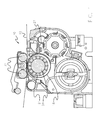
- a developer station 10 for development electrostatic images includes an imaging element 12 for electrostatic Images, which is also referred to below as a photoconductor element and on the one electrostatic image is generated, and a magnetic brush 14 that rotates Toner transfer jacket 18, a mixture 16 of hard magnetic carrier particles and Toner (also referred to as developer below) and a rotating one Magnetic core 20 includes.
- the photoconductor element 12 is designed as an arc-like film.
- the photoconductor element can also be constructed differently, e.g. as a drum.
- the photoconductor film 12 is relatively elastic, stands usually under tension, and two support rods 32 can be provided, the Imaging element in a desired position with respect to the Hold the toner transfer case 18 as shown in FIG. 1.
- the photoconductor element 12 and the toner transfer jacket 18 rotate so that the opposite surfaces of the toner transfer jacket 18 and the photoconductor member 12 move in the same direction.
- the photoconductor element 12 and the Toner transfer jacket 18 define a space which is called Toner transfer nip 34 is referred to.
- the developer 16 is before Toner transfer nip 34 applied to the toner transfer jacket 18 and at the Transfer of developer 16 to the toner transfer jacket is Average speed at which the developer moves through the narrow Toner transfer nip 34 moves, initially slower than the speed of the Developer 16 to other locations on the toner transfer jacket 18. Therefore, accumulates Developer 16 immediately before the toner transfer nip 34 in a so-called Stowage area until enough pressure has built up in the toner transfer nip 34 to cause the Developer 16 to compress so much that it deals with the same Mass velocity like developer 16 on the rest of the toner transfer jacket 18 moves.
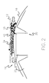
- Adjacent to the toner transfer jacket 18 is a metering and Scraper element 27 is provided, which is used to set the toner transfer jacket supplied developer amount closer to the toner transfer jacket 18 or further is movable away from this.
- the toner station comprises a stainless steel toner transfer jacket containing a 14-pin magnetic core and having a desired diameter of 5.08 cm (2 inches).
- the alternating north and south poles have a field strength of approximately 0.1 T (1000 Gauss).
- toner particles 50 and Carrier particles 52 are electrostatically charged and have opposite charges, so that they attract each other.
- the toner particles 50 contact the carrier particles 52 and take up a charge q in a triboelectric process.
- an equally strong, opposite charge Q -q is distributed on the surface of the carrier particle 52.
- the force between the particles emanating from the free charges behaves as if the charges q and Q were concentrated in the center of the respective particle and is calculated according to equation (1), where r ⁇ R C + R T.
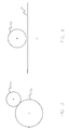
- FIG. 4 shows a toner particle 50 adjoining a carrier particle 52, the diameter of the carrier particle 52 being significantly larger than that of the toner particle 50. The difference in diameter is so great that the carrier particle 52 as a flat, conductive, grounded on the toner particle 52 adjacent level can be displayed.
- the charge q of the toner particle 50 generates an electrostatic mirror charge -q in the carrier particle 52.
- This electrostatic mirror charge is not to be confused with the electrographic image charge of the photoconductor element 12.
- the electrostatic mirror charge is actually a distribution of free charges on the surface of the carrier particle 52, but it can be represented as an electrostatic mirror charge according to FIG. 4.
- the point-level model is a good approximation for very large carriers with a high but finite conductivity or a very high dielectric constant >> 1.
- ⁇ C For a large carrier with a dielectric constant ⁇ C applies and
- typical toner properties for example a toner charge of 20 ⁇ C / g, an average toner diameter of 11.5 ⁇ m and a density of approx. 1 g / cm 3 , the toner has a charge of approximately 1.6 ⁇ 10 -14 C (4.78 x 10 -5 statcoulomb), and the toner particle 50 contacting the electrostatic mirror charge in the case of a conductive carrier particle 52 shown as a flat surface is approximately -1.73 x 10 -8 N (-1.73 x 10 -3 dynes).
- toners of larger or smaller diameters can be used in the present invention.
- the electrostatic potential energy that binds the toner particle 50 to a conductive carrier particle 52 is approximately -9.93 x 10 -14 J (-9.93 x 10 -7 ergs).
- the force and potential of large dielectric carriers with a high dielectric constant ⁇ C approximately correspond to the force and potential of large conductive carriers.
- a toner particle 50 that is triboelectrically charged on the surface of a spherical carrier particle 52 receives a charge q that is distributed uniformly on the surface of the toner particle 52 while the carrier particle takes up a charge Q.
- the center point of the toner particle 50 with the charge q is spaced apart from the center point of the carrier particle 52 by the radius r.
- the carrier is conductive, part of its total charge Q is concentrated on the surface of the carrier particle 52 in an area 54 adjacent to the toner particle 50, resulting in an uneven charge distribution.
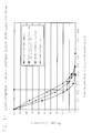
- FIGS. 6 and 7 show the effects of changes in the relative size of the toner and carrier particles.
- FIG. 7 is a log-log plot, ie a diagram in which the two axes are shown in logarithmic division.
- Fig. 6 shows that the contact force with a charge point toner particle with a dielectric spherical carrier particle is always lower than with a conductive carrier particle, and that it is greater than the Coulomb force.
- the force is greatest when the carrier particles are small, ie R C corresponds approximately to RT.
- the force approaches the limit of the counterforce from a dielectric flat surface.
- the force qE exerted on the toner particle by the electrostatic field for image development should be as large as possible compared to the attractive force binding the toner to the carrier. This can be achieved with carrier particles with a radius R C , for which R C ⁇ 1.5R T applies in combination with a high dielectric constant.
- the preferred high dielectric constant results in an electrical imaging field which, for practical reasons, is as strong as a field generated by conductive supports.
- the dielectric constant for commercially available carrier particles from Heidelberg Digital is approximately 5 x 10 3 .
- a dielectric constant of 6 at 60% packing reduces the effective dielectric constant by 20%, which leads to a 20% reduction in the electric field for image development, but also reduces the attraction force depending on n by 10% -29%.
- a dielectric constant of 3 reduces the effective dielectric constant and electric field by 33%, but also reduces the attractive force by 16% -50%.
- the dielectric constant for the carrier particles can be between 6 and ⁇ . Similar results are obtained with the Maxwell Wagner model.
- the force and the potential change very rapidly with increasing distance r for large carrier particles, while the force decreases significantly more slowly for smaller carrier particles, as is clear from FIG. 7.
- the curves correspond to a toner distance from contact with the carrier surface up to ten times the toner radius between the particle surfaces.
- the force can decrease faster than 1 / r 30 , and it behaves similarly to a surface force.
- the triboelectric charge and the charge-induced polarization approach a dependency of 1 / r 2 up to 1 / r 3 at moderate intervals.
- the Coulomb force is also drawn in as a reference curve. Because of the 1 / r2 dependency of the force and the 1 / r dependency of the potential, the coulomb behavior is represented by a straight line of negative slope in a log-log plot, the y-passage being 2log 10 (q).
- the Coulomb force and the forces caused by charge-induced polarization of the carrier by the toner were used to calculate the attractive force between the toner and carrier.
- the influence of the forces caused by the polarization of the toner by the carrier on the attractive force between the toner and the carrier is substantially less and can therefore be neglected in the present approximation, the dielectric constant ⁇ T of the resin toner being approximately 3.
- the force between the toner particle and the carrier particle results in the case of a conductive carrier particle according to Coulomb's law, with all interactions between the two charges on the toner particle and the three mirror charges being summed "inside" the carrier particle.
- q 1 plus the potential energy of both charges is equal to q 1 and due to the potential of the uniform charge q 2 by the potential of the concentrated charge q 2 plus the Coulomb potential for the interaction of the carrier charge Q and the toner charges q 1 and q 2 the potential energy of the potential energy for q 1 and for q 2 .
- the force can be determined by differentiation: Charge concentrations cause a significant increase in the attraction between toner particles and carrier particles.
- FIG. 9 shows the force on a toner particle with a concentration of 10% of its charge in a point adjacent to the carrier for dielectric and for conductive carrier particles with a distance of 0.05 toner radii between the surface of the toner particle and the carrier particle. Similar to FIG. 6, the force with a conductive carrier particle is always stronger than the force with a dielectric carrier particle.
- the force shown in FIG. 9 for a dielectric carrier particle and a toner with concentrated charge decreases with increasing carrier particle diameter, but is always significantly greater than the force shown in FIG. 6 for a dielectric carrier particle and a toner with uniform charge distribution.
- the dielectric carrier data shown in FIG. 9 was calculated from the sum of the first 200 terms of equation (19). Very similar results are obtained if the force is calculated according to the slope of the potential energy according to equation (18). The potential energy calculated according to equation (18) converges for rR T > R C. For very large n, the force calculated according to equation (19) diverges to infinity. However, if one chooses a reasonable number of terms for each sum in such a way that the nth term is significantly smaller than the first term, one obtains a good agreement for the forces calculated according to equation (19) and for those obtained by means of a numerical evaluation the slope of the curve for the potential energy forces calculated according to equation (18).
- FIG. 9 shows a decrease in the attractive forces for large carrier particles of up to five times that of smaller carrier particles, the radius R C of which approximately corresponds to 30 R T.
- the preferred particle size is a few times the size of the toner particles, since in this preferred carrier size range the likelihood that a strong concentration of charge develops on the toner surface is significantly reduced.
- the relative size of the carrier particles and the toner particles is of great importance for minimizing an uneven charge distribution, which is caused by the fact that the toner particles only contact the carrier particles on a small portion of their surface. This phenomenon is influenced to some extent by the empty volume in the toner transfer nip 34 (see Figures 1 and 2), which in turn determines how much the developer is packed under the pressure applied in the toner transfer nip 34.
- the empty volume in the toner transfer nip 34 can be calculated by assuming that the volume in the toner transfer nip 34 is limited by the actual 0.4 mm (0.018 inch) distance between the photoconductor element 12 and the toner transfer jacket 18 that is actually occupied by each toner particle Volume calculated, and this volume divided by the packing density f for dense, randomly packed spheres. With a very high packing density, f ⁇ is 0.6. A spherical shape is assumed for the toner and carrier particles.
- N T DMAD x TC / ( ⁇ T V T )
- N C DMAD x (1-TC) / ( ⁇ C V C )
- DMAD the developer mass area density
- TC the toner content of the developer
- ⁇ T the density of the toner particles
- ⁇ C the density of the carrier particles
- k the inter-spatial toner fraction
- the available empty volume both inside and outside the Toner transfer nip largely depends on the extent to which the toner particles fit into the empty spaces that arise when packing the carrier particles. If the Toner particles are smaller than those generated by the packing of the carrier particles Whitespaces, the volume occupied by the developer depends almost exclusively on the carrier particles. However, it can be seen that with increasing Toner particle diameter relative to the carrier particle diameter the ability of Toner particles to fit into the voids in the carrier particle packaging structure decreases and the toner particles increasingly contribute to the total developer volume, making the Empty volume is reduced.
- Neest- neighbor distribution functions in many-body systems (for example: distribution functions for nearest neighbors in multi-body systems), in Phys. Rev. A, Vol. 41, No. 4 (15.02.1990), p. 2059ff and in Lu, B. and Torquato, p. "Neurest-surface distribution functions for polydispersed particle systems” (about: distribution functions in close proximity to the Surface for polydisperse systems), in Phys. Rev. A., Vol. 45, No. 8 (15.04.1992) method described.
- FIG. 11 shows the size distribution of continuous and defined empty spaces for random systems of packed spheres with a radius 1.
- the packing density lies for that Model with defined empty spaces is 0.6 and lies for the model with continuous White spaces between 0.6 and 0.2.
- For a toner particle with the radius x shows the y-axis in FIG. 11 the percentage of empty space that the particle can take up without to distort the packed structure or more than one carrier particle at a time to contact. Form due to strong magnetic interactions between particles the collapsed carrier chains with a high probability clusters, their overall structure between the model with defined empty spaces and the model with continuous There is empty space.
- the toner particle diameter is significantly smaller than the carrier particle diameter or if the packing density is significantly less than 0.6, then the toner particles are significantly smaller than the empty space structures and therefore fit easily into the empty space, with the result that the toner particles only have one carrier particle in one Contact the point, such as shown in Fig. 12.
- the size of the toner particles with respect to the carrier particles is selected such that the toner particles are either large enough to just fit in the space or slightly too large to fit in the space, and if the packing density is maximum , the contact between the toner particles and the carrier particles is also maximum, as shown in FIG. 12.
- the toner is preferred, with a relative size of between about 1 / 10R C and 2 / 3R C, corresponding to a volume size of between about 1.5R T and 10R T ,
- a toner with a relative size of between about 2 / 10R C and 1 / 2R C is preferred, which corresponds to a carrier size of between about 2R T and 5R T.
- the importance of maximizing contact between the toner particle surface and the carrier particle lies in the one generated by triboelectric charge Surface charge distribution.
- a toner particle contains a carrier particle with only one small part of its surface contacted, so the small take direct contact part as well as a point opposite the contact point a charge on what leads to an uneven charge distribution on the surface of the toner particle.
- a spherical charge distribution is clearly preferred, since the through uneven charge distribution caused by small toner particles can cause that the electrostatic adhesive force dominates and so the separation of the toner particle from the first carrier particle difficult.
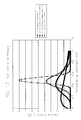
- the size distribution of particles is often described according to a Schulz distribution: where z> -1.
- a spherical charge distribution can be achieved by using instead of Grinding produced toner monodisperse, spherical, chemically developed toner particles used with a narrow size distribution.
- Such chemically produced toners the Use preferred in the context of the present invention are known.
- the toner particles preferably have the appropriate one Size relative to the carrier particles. If the typical toner size and the typical Carrier size to meet the preferred proportions, increase tighter Size distributions are the percentage of toner and carrier particles that make up the preferred size proportions. Narrower toner particle size distributions with z> 20 are preferred.
- the same benefits can be achieved by using spherical, chemically manufactured carrier particles with a narrow size distribution are used as this a spherical, uniform charge distribution on the carrier particles and on the Toner particles as well as a high percentage of toner particles which is preferred Size ratio with the carrier particles.
Landscapes
- Physics & Mathematics (AREA)
- General Physics & Mathematics (AREA)
- Developing Agents For Electrophotography (AREA)
Abstract
Description
- Fig. 1
- eine Seitenansicht einer Vorrichtung zur Entwicklung elektrofotografischer Bilder gemäß einem Aspekt der vorliegenden Erfindung,
- Fig. 2
- eine Seiten-Querschnittsansicht einer Vorrichtung zur Entwicklung elektrostatografischer Bilder gemäß einem Aspekt der vorliegenden Erfindung,
- Fig. 3
- eine schematische Darstellung der Interaktion zwischen einem Tonerpartikel und einem Trägerpartikel mit gleicher und entgegengesetzter Ladung,
- Fig. 4
- eine schematische Darstellung der Interaktion zwischen einem Tonerpartikel und einem Trägerpartikel, wobei der Radius des Trägerpartikels deutlich größer ist als der Radius des Tonerpartikels,
- Fig. 5
- eine schematische Darstellung der Auswirkungen von ladungsbedingter Polarisierung auf einen leitfähigen, sphärischen Trägerpartikel,
- Fig. 6
- eine grafische Darstellung der Anziehungskraft zwischen einem Trägerpartikel und einem Tonerpartikel in Abhängigkeit von der Größe des Trägerpartikels und den elektrischen Eigenschaften der einander kontaktierenden Toner- und Trägerpartikel,
- Fig. 7
- eine grafische Darstellung der Anziehungskraft zwischen einem Trägerpartikel und einem Tonerpartikel in Abhängigkeit von der Größe des Trägerpartikels bei verschiedenen Abständen,
- Fig. 8
- eine schematische Darstellung der Interaktion zwischen einem Tonerpartikel mit ungleichmäßiger Ladungsverteilung und einem Trägerpartikel,
- Fig. 9
- eine grafische Darstellung der Anziehungskraft zwischen einem Trägerpartikel und einem Tonerpartikel in Abhängigkeit von der Größe des Trägerpartikels und den elektrischen Eigenschaften der Toner- und Trägerpartikel bei einem Abstand von 0,05 Tonerradien und bei einer Konzentration von 10% der Tonerladung an dem der Trägeroberfläche am nächsten gelegenen Punkt,
- Fig. 10A
- eine schematische Darstellung eines von gepackten Trägerpartikeln gebildeten Leerraum in Form eines Tetraeders,
- Fig. 10B
- eine schematische Darstellung eines von gepackten Trägerpartikeln gebildeten Leerraums in Form eines Oktaeders,
- Fig. 10C
- eine schematische Darstellung eines von gepackten Trägerpartikeln gebildeten Leerraums in Form eines trigonalen Prismas mit drei angrenzenden halben Oktaedern,
- Fig. 10D
- eine schematische Darstellung eines von gepackten Trägerpartikeln gebildeten archimedischen Antiprismas mit zwei angrenzenden halben Oktaedern,
- Fig. 10E
- eine schematische Darstellung eines von gepackten Trägerpartikeln gebildeten Leerraums in Form eines tetragonalen Dodekaeders,
- Fig. 11
- eine grafische Darstellung der Größenverteilung der von Trägerpartikeln in einem zufälligen System dicht gepackter Kugeln gebildeten Leerräume,
- Fig. 12
- eine schematische Darstellung gepackter Träger- und Tonerpartikel, wenn die Trägerpartikel bedeutend größer sind als die Tonerpartikel,
- Fig. 13
- eine grafische Darstellung der Partikelgrößenverteilung,
- Fig. 14
- eine grafische Darstellung der Größenverteilung der Leerräume in einem zufälligen System dicht gepackter Kugeln für Trägerpartikel mit enger und breiter Größenverteilung.




- 10
- Vorrichtung zur Entwicklung elektrostatischer Bilder
- 12
- elektrostatisches Bilderzeugungselement/Fotoleiterelement
- 14
- Magnetbürste
- 16
- Entwickler/Mischung aus hartmagnetischen Trägerpartikeln und Toner
- 18
- Tonerübertragungsmantel
- 20
- Magnetkern
- 21
- Magnet
- 27
- Dosier- und Abstreifelement
- 32
- Stützstangen
- 34
- Tonerübertragungsspalt
- 50
- Tonerpartikel
- 52
- Trägerpartikel
- 54
- Bereich
- q
- Ladung
- Q
- Ladung
- Q'
- Ladung
- q1
- Ladung
- q1'
- Ladung
- q2
- Ladung
- q2'
- Ladung
- RC
- Radius des Trägerpartikels
- RT
- Radius des Tonerpartikels
Claims (16)
- Ein Zweikomponentenentwickler (16) zur Verwendung im elektrografischen Druckvorgang, wobei der Zweikomponentenentwickler (16) im Wesentlichen sphärische Tonerpartikel (50) mit einem Radius (RT) und im Wesentlichen sphärische magnetische Trägerpartikel (52) mit einem Radius (RC) enthält, und wobei der Radius (RC) der Trägerpartikel (52) zwischen dem 1,5fachen des Radius (RT) der Tonerpartikel (50) und dem 10fachen des Radius (RT) der Tonerpartikel (50) beträgt.
- Zweikomponentenentwickler (16) zur Verwendung im elektrografischen Druckvorgang, wobei der Zweikomponentenentwickler (16) im Wesentlichen sphärische Tonerpartikel (50) mit einem Radius (RT) und im Wesentlichen sphärische magnetische Trägerpartikel (52) mit einem Radius (RC) und einer dielektrischen Konstante εC enthält, die mindestens ungefähr 6 beträgt, und wobei der Radius (RC) der Trägerpartikel (52) zwischen dem ungefähr 1,5fachen des Radius (RT) der Tonerpartikel (50) und dem ungefähr 10fachen des Radius (RT) der Tonerpartikel (50) beträgt.
- Entwickler nach einem der Ansprüche 1 bis 2,
dadurch gekennzeichnet, dass die Trägerpartikel (52) eine dielektrische Konstante εC aufweisen, die mehr als 10 beträgt. - Entwickler nach einem der Ansprüche 1 bis 2,
dadurch gekennzeichnet, dass die Trägerpartikel (52) eine dielektrische Konstante εC von mehr als 100 aufweisen. - Entwickler nach einem der Ansprüche 1 bis 2,
dadurch gekennzeichnet, dass die Trägerpartikel (52) eine dielektrische Konstante εC von mehr als ungefähr 298 aufweisen. - Entwickler nach einem der Ansprüche 1 bis 5,
dadurch gekennzeichnet, dass der Radius (RC) der Trägerpartikel (52) zwischen ungefähr dem ungefähr Zweifachen des Radius (RT) der Tonerpartikel (50) und dem ungefähr Fünffachen des Radius (RT) der Tonerpartikel (50) beträgt. - Entwickler nach einem der Ansprüche 1 bis 6,
dadurch gekennzeichnet, dass die Trägerpartikel (52) eine Größenverteilung gemäß der Schulzschen Verteilung mit z größer als ungefähr 6 aufweisen. - Entwickler nach einem der Ansprüche 1 bis 6,
dadurch gekennzeichnet, dass die Trägerpartikel (52) eine Größenverteilung gemäß der Schulzschen Verteilung mit z größer als ungefähr 10 aufweisen. - Entwickler nach einem der Ansprüche 1 bis 6,
dadurch gekennzeichnet, dass die Trägerpartikel (52) eine Größenverteilung gemäß der Schulzschen Verteilung mit z größer als ungefähr 50 aufweisen. - Entwickler nach einem der Ansprüche 1 bis 6,
dadurch gekennzeichnet, dass die Trägerpartikel (52) eine Größenverteilung gemäß der Schulzschen Verteilung mit z größer als ungefähr 100 aufweisen. - Entwickler nach einem der Ansprüche 1 bis 6,
dadurch gekennzeichnet, dass die Tonerpartikel (50) eine Größenverteilung gemäß der Schulzschen Verteilung mit z größer als ungefähr 20 aufweisen. - Entwickler nach einem der Ansprüche 1 bis 6,
dadurch gekennzeichnet, dass die Tonerpartikel (50) eine Größenverteilung gemäß der Schulzschen Verteilung mit z größer als ungefähr 30 aufweisen. - Entwickler nach einem der Ansprüche 1 bis 6,
dadurch gekennzeichnet, dass die Tonerpartikel (50) eine Größenverteilung gemäß der Schulzschen Verteilung mit z größer als ungefähr 50 aufweisen. - Entwickler nach Anspruch 1,
dadurch gekennzeichnet, dass die Tonerpartikel (50) eine Größenverteilung gemäß der Schulzschen Verteilung mit z größer als ungefähr 100 aufweisen. - Verfahren zur Herstellung von elektrografischen Bildern,
dadurch gekennzeichnet, dass das Verfahren die folgenden Schritte umfasst:(a) Bereitstellen eines elektrografischen Druckers (10) mit einem Bebilderungselement (12), einem an das Bebilderungselement (12) angrenzenden Tonerübertragungsmantel (18), der zwischen sich und dem Bebilderungselement (12) ein externes elektrisches Feld zur Bildentwicklung definiert, und einem Zweikomponentenentwickler (16), wobei es sich bei dem Entwickler um einen Entwickler gemäß eines der Ansprüche 1 bis 14 handelt;(b) Veranlassen des Entwicklers (16) zu einer Bewegung durch das externe elektrische Feld, so dass dieser mit einem elektrostatischen Bild auf dem Bebilderungselement (12) zusammenwirkt. - Verfahren nach Anspruch 15,
dadurch gekennzeichnet, dass das externe elektrische Feld zur Bildentwicklung schwächer ist als das durch einen gleichmäßig geladenen Tonerpartikel (50) mit einer Ladung (q) und einem Radius (RT) erzeugte elektrische Feld.
Applications Claiming Priority (2)
| Application Number | Priority Date | Filing Date | Title |
|---|---|---|---|
| US10/054,514 US6946230B2 (en) | 2001-11-13 | 2001-11-13 | Electrostatic image developing processes and compositions |
| US54514 | 2001-11-13 |
Publications (2)
| Publication Number | Publication Date |
|---|---|
| EP1310831A2 true EP1310831A2 (de) | 2003-05-14 |
| EP1310831A3 EP1310831A3 (de) | 2004-07-21 |
Family
ID=21991615
Family Applications (1)
| Application Number | Title | Priority Date | Filing Date |
|---|---|---|---|
| EP02025226A Withdrawn EP1310831A3 (de) | 2001-11-13 | 2002-11-12 | Zweikomponentenentwickler und Herstellungsverfahren |
Country Status (3)
| Country | Link |
|---|---|
| US (1) | US6946230B2 (de) |
| EP (1) | EP1310831A3 (de) |
| DE (1) | DE10252883A1 (de) |
Families Citing this family (9)
| Publication number | Priority date | Publication date | Assignee | Title |
|---|---|---|---|---|
| WO2001088628A1 (en) * | 2000-05-17 | 2001-11-22 | Heidelberg Digital, L.L.C. | Electrostatic image developing process with optimized setpoints |
| US6728503B2 (en) | 2001-02-28 | 2004-04-27 | Heidelberger Druckmaschinen Ag | Electrophotographic image developing process with optimized average developer bulk velocity |
| US20060150902A1 (en) * | 2004-03-09 | 2006-07-13 | Eastman Kodak Company | Powder coating apparatus and method of powder coating using an electromagnetic brush |
| US7481884B2 (en) * | 2004-03-09 | 2009-01-27 | Eastman Kodak Company | Powder coating apparatus and method of powder coating using an electromagnetic brush |
| US7426361B2 (en) | 2005-09-01 | 2008-09-16 | Eastman Kodak Company | Developer mixing apparatus having four ribbon blenders |
| US7885584B2 (en) * | 2007-06-29 | 2011-02-08 | Eastman Kodak Company | Self-cleaning electrophotographic toning roller system |
| US8224209B2 (en) * | 2009-08-18 | 2012-07-17 | Eastman Kodak Company | High-frequency banding reduction for electrophotographic printer |
| US8311463B2 (en) * | 2009-08-18 | 2012-11-13 | Eastman Kodak Company | Method and system to reduce high-frequency banding for electrophotographic development stations |
| JP5875453B2 (ja) * | 2012-04-19 | 2016-03-02 | キヤノン株式会社 | 自動追尾装置 |
Family Cites Families (99)
| Publication number | Priority date | Publication date | Assignee | Title |
|---|---|---|---|---|
| JPS5115992B2 (de) * | 1971-12-17 | 1976-05-20 | ||
| US4546060A (en) | 1982-11-08 | 1985-10-08 | Eastman Kodak Company | Two-component, dry electrographic developer compositions containing hard magnetic carrier particles and method for using the same |
| JPS59185350A (ja) * | 1983-04-06 | 1984-10-20 | Minolta Camera Co Ltd | 磁性現像剤 |
| US4602863A (en) | 1983-07-01 | 1986-07-29 | Eastman Kodak Company | Electrographic development method, apparatus and system |
| US4473029A (en) | 1983-07-01 | 1984-09-25 | Eastman Kodak Company | Electrographic magnetic brush development method, apparatus and system |
| US4531832A (en) | 1983-08-01 | 1985-07-30 | Eastman Kodak Company | Electrographic apparatus, method and system employing image development adjustment |
| US4496643A (en) | 1984-03-23 | 1985-01-29 | Eastman Kodak Company | Two-component dry electrostatic developer composition containing onium charge control agent |
| US4887132A (en) | 1984-04-06 | 1989-12-12 | Eastman Kodak Company | Electrographic development apparatus having a ribbon blender |
| US4637973A (en) | 1984-11-15 | 1987-01-20 | Konishiroku Photo Industry Co., Ltd. | Image forming process for electrophotography |
| JPH0648396B2 (ja) * | 1984-11-30 | 1994-06-22 | 三田工業株式会社 | 二成分系現像剤 |
| US4634286A (en) | 1985-09-06 | 1987-01-06 | Eastman Kodak Company | Electrographic development apparatus having a continuous coil ribbon blender |
| US4714046A (en) | 1985-11-20 | 1987-12-22 | Eastman Kodak Company | Electrographic magnetic brush development apparatus and system |
| US4671207A (en) | 1985-12-11 | 1987-06-09 | Eastman Kodak Company | Magnetic brush development apparatus |
| US4764445A (en) | 1987-06-15 | 1988-08-16 | Eastman Kodak Company | Electrographic magnetic carrier particles |
| US4825244A (en) | 1987-11-23 | 1989-04-25 | Eastman Kodak Company | Development station with improved mixing and feeding apparatus |
| US4922302A (en) | 1988-07-07 | 1990-05-01 | Eastman Kodak Company | Device for developing electrostatic images on a film belt |
| US5001028A (en) | 1988-08-15 | 1991-03-19 | Eastman Kodak Company | Electrophotographic method using hard magnetic carrier particles |
| US5049471A (en) | 1988-11-28 | 1991-09-17 | Mita Industrial Co., Ltd. | Magnetic brush development process |
| DE68912537T2 (de) | 1988-11-28 | 1994-05-05 | Mita Industrial Co Ltd | Magnetbürstenentwicklungsverfahren. |
| JPH03170978A (ja) | 1989-11-29 | 1991-07-24 | Mita Ind Co Ltd | 現像装置 |
| US5019796A (en) | 1989-12-22 | 1991-05-28 | Eastman Kodak Company | Bar magnet for construction of a magnetic roller core |
| US4967236A (en) | 1989-12-27 | 1990-10-30 | Eastman Kodak Company | Charge retention xeroprinting |
| US5484680A (en) | 1990-02-28 | 1996-01-16 | Hitachi Metals, Ltd. | Magnetic brush developing method |
| US5061586A (en) | 1990-04-05 | 1991-10-29 | Eastman Kodak Company | Glass composite magnetic carrier particles |
| US5043760A (en) | 1990-04-09 | 1991-08-27 | Eastman Kodak Company | Carrier particle loosening device |
| US5040003A (en) | 1990-06-04 | 1991-08-13 | Eastman Kodak Company | Method and apparatus for recording color with plural printheads |
| US5106714A (en) | 1990-08-01 | 1992-04-21 | Eastman Kodak Company | Interdispersed two-phase ferrite composite and electrographic magnetic carrier particles therefrom |
| US5063399A (en) | 1990-08-06 | 1991-11-05 | Eastman Kodak Company | Electrophotographic apparatus having reduced drum drive flutter |
| JP2979599B2 (ja) | 1990-08-10 | 1999-11-15 | ミノルタ株式会社 | 電子写真現像法 |
| US5095340A (en) | 1990-09-06 | 1992-03-10 | Eastman Kodak Company | Method of controlling the operation of a magnetic brush toning station |
| US5104761A (en) | 1990-09-14 | 1992-04-14 | Eastman Kodak Company | Interdispersed three-phase ferrite composite and electrographic magnetic carrier particles therefrom |
| US5066981A (en) | 1990-10-15 | 1991-11-19 | Eastman Kodak Company | Mechanism for responsively spacing a development roller |
| US5047807A (en) | 1990-10-15 | 1991-09-10 | Eastman Kodak Company | Development apparatus having a plate scavenging device |
| US5227265A (en) | 1990-11-30 | 1993-07-13 | Eastman Kodak Company | Migration imaging system |
| US5138388A (en) | 1990-12-24 | 1992-08-11 | Eastman Kodak Company | Method and apparatus for removing unexposed marking particles with magnetic carrier particles |
| JPH05504422A (ja) | 1990-11-30 | 1993-07-08 | イーストマン・コダック・カンパニー | 移動画像形成システム |
| US5111245A (en) | 1990-12-03 | 1992-05-05 | Eastman Kodak Company | Apparatus for positioning a development unit with respect to an image member |
| US5182608A (en) | 1990-12-03 | 1993-01-26 | Eastman Kodak Company | Method and apparatus for applying toner to an electrostatic image |
| US5237127A (en) | 1990-12-24 | 1993-08-17 | Eastman Kodak Company | Development apparatus having means for translating development units in producing multicolor images |
| US5247331A (en) | 1991-11-19 | 1993-09-21 | Eastman Kodak Company | Color image forming apparatus with translatable development apparatus having an integral wheel mount |
| US5084739A (en) | 1991-01-22 | 1992-01-28 | Eastman Kodak Company | Self-loading cleaning blade and holder therefor |
| US5132732A (en) | 1991-01-22 | 1992-07-21 | Eastman Kodak Company | Dual axis displacement lifting mechanism for a development apparatus |
| US5146278A (en) | 1991-03-15 | 1992-09-08 | Eastman Kodak Company | Apparatus for applying toner to an electrostatic image |
| US5300988A (en) | 1991-06-07 | 1994-04-05 | Eastman Kodak Company | Toning station for selectively applying toner to an electrostatic image |
| US5162854A (en) | 1991-06-07 | 1992-11-10 | Eastman Kodak Company | Image forming apparatus having at least two toning stations |
| US5148220A (en) | 1991-06-07 | 1992-09-15 | Eastman Kodak Company | Toning station drive for image-forming apparatus |
| US5196887A (en) | 1991-06-07 | 1993-03-23 | Eastman Kodak Company | Image forming apparatus having a magnetic brush toning station |
| JPH056099A (ja) | 1991-06-28 | 1993-01-14 | Mita Ind Co Ltd | 現像方法 |
| US5184194A (en) | 1991-10-28 | 1993-02-02 | Eastman Kodak Company | Carrier particle scavenging device |
| US5190842A (en) | 1991-12-19 | 1993-03-02 | Eastman Kodak Company | Two phase ferroelectric-ferromagnetic composite carrier |
| US5190841A (en) | 1991-12-19 | 1993-03-02 | Eastman Kodak Company | Two-phase ferroelectric-ferromagnetic composite and carrier therefrom |
| US5245388A (en) | 1992-04-27 | 1993-09-14 | Eastman Kodak Company | Image forming apparatus including indexible toning units |
| US5241327A (en) | 1992-06-01 | 1993-08-31 | Eastman Kodak Company | Method and apparatus for removing untacked toner from images |
| US5280302A (en) | 1992-06-05 | 1994-01-18 | Eastman Kodak Company | Recording apparatus with magnetic brush removal of non-tacked toner |
| US5298358A (en) | 1992-06-29 | 1994-03-29 | Eastman Kodak Company | Method and apparatus for reproducing image information |
| US5296898A (en) | 1992-08-05 | 1994-03-22 | Eastman Kodak Company | Method for producing images |
| US5332645A (en) | 1992-09-28 | 1994-07-26 | Eastman Kodak Company | Low dusting carriers |
| US5347345A (en) | 1992-10-19 | 1994-09-13 | Eastman Kodak Company | Method and apparatus of creating two-color images in a single pass |
| US5306592A (en) | 1992-10-29 | 1994-04-26 | Eastman Kodak Company | Method of preparing electrographic magnetic carrier particles |
| US5268249A (en) | 1992-10-29 | 1993-12-07 | Eastman Kodak Company | Magnetic carrier particles |
| US5339140A (en) | 1992-11-04 | 1994-08-16 | Eastman Kodak Company | Method and apparatus for control of toner charge |
| US5293201A (en) | 1992-11-09 | 1994-03-08 | Eastman Kodak Company | Image forming apparatus in which toner is recycled between toner applying and cleaning stations |
| US5296905A (en) | 1992-11-12 | 1994-03-22 | Eastman Kodak Company | Cleaning device using magnetic particulate cleaning material |
| US5291259A (en) | 1992-11-12 | 1994-03-01 | Eastman Kodak Company | Image forming apparatus having toner cleaning device |
| US5400124A (en) | 1992-11-16 | 1995-03-21 | Eastman Kodak Company | Development station having a roughened toning shell |
| US5313993A (en) | 1992-12-03 | 1994-05-24 | Eastman Kodak Company | Toner container and receiving apparatus therefor |
| US5255053A (en) | 1992-12-03 | 1993-10-19 | Eastman Kodak Company | Image forming apparatus having a transfer drum, an image member cartridge and exposure means |
| US5282002A (en) | 1992-12-03 | 1994-01-25 | Eastman Kodak Company | Image forming apparatus having a sump component for multiple developing units |
| US5296894A (en) | 1992-12-03 | 1994-03-22 | Eastman Kodak Company | Image forming apparatus and an image member cartridge containing a photoconductive drum |
| US5268719A (en) | 1992-12-03 | 1993-12-07 | Eastman Kodak Company | Image forming apparatus having a positioning mechanism for multiple developing units |
| JPH06289689A (ja) * | 1993-04-01 | 1994-10-18 | Hitachi Metals Ltd | 画像形成方法 |
| US5376492A (en) | 1993-05-20 | 1994-12-27 | Eastman Kodak Company | Method and apparatus for developing an electrostatic image using a two component developer |
| US5409791A (en) | 1993-05-20 | 1995-04-25 | Eastman Kodak Company | Image forming method and apparatus |
| US5325161A (en) | 1993-05-24 | 1994-06-28 | Eastman Kodak Company | Device for developing an electrostatic image on an image member |
| US5347347A (en) | 1993-05-25 | 1994-09-13 | Eastman Kodak Company | Apparatus for applying toner to an electrostatic image having improved developer flow |
| US5592268A (en) | 1994-07-22 | 1997-01-07 | Brother Kogyo Kabushiki Kaisha | Mechanism to prevent toner leakage from an image forming unit |
| US5500320A (en) | 1994-08-29 | 1996-03-19 | Eastman Kodak Company | High speed developer compositions with ferrite carriers |
| US5512404A (en) | 1994-08-29 | 1996-04-30 | Eastman Kodak Company | Developer compositions exhibiting high development speeds |
| US5648842A (en) | 1995-01-21 | 1997-07-15 | Ricoh Company, Ltd. | Methods and systems for cleaning residual toner from image-developing device |
| US5705307A (en) | 1995-08-23 | 1998-01-06 | Eastman Kodak Company | Method of developing electrostatic images |
| US5713064A (en) | 1996-01-17 | 1998-01-27 | Eastman Kodak Company | Method and apparatus for forming toner images with two distinct toners |
| US5748218A (en) | 1996-01-17 | 1998-05-05 | Eastman Kodak Company | Method for forming toner images with two distinct toners |
| US5701550A (en) | 1996-03-22 | 1997-12-23 | Eastman Kodak Company | Method and apparatus for controlling charge on toner in a toning station |
| EP0801334B1 (de) * | 1996-04-08 | 2001-08-29 | Canon Kabushiki Kaisha | Beschichtete magnetische Trägerteilchen, zwei-Komponententyp-Entwickler und Entwicklungsverfahren |
| JP3639382B2 (ja) * | 1996-07-15 | 2005-04-20 | 株式会社Neomax | 静電荷像現像用現像剤およびそれを使用した静電荷像現像方法 |
| JP3535681B2 (ja) | 1996-12-04 | 2004-06-07 | キヤノン株式会社 | 画像形成装置 |
| US5853941A (en) | 1996-12-11 | 1998-12-29 | Eastman Kodak Company | Eliminating triboelectrically generated background in an electrophotographically produced image |
| US5732311A (en) | 1996-12-26 | 1998-03-24 | Eastman Kodak Company | Compliant electrographic recording member and method and apparatus for using same |
| US5923933A (en) | 1997-02-21 | 1999-07-13 | Hitachi Koki Co., Ltd. | Electrophotographic apparatus |
| EP0884653B1 (de) * | 1997-06-13 | 2003-05-02 | Canon Kabushiki Kaisha | Bilderzeugungsverfahren, Bilderzeugungsgerät und Prozesskassette |
| US5835832A (en) | 1997-06-26 | 1998-11-10 | Eastman Kodak Company | Optimal toner charge for use with a compliant transfer intermediate |
| US5926679A (en) | 1997-12-08 | 1999-07-20 | Eastman Kodak Company | Method and apparatus for forming an image for transfer to a receiver sheet using a clear toner and sintering of a pigmented toner layer |
| US5998076A (en) | 1998-03-09 | 1999-12-07 | Xerox Corporation | Carrier |
| US5923937A (en) | 1998-06-23 | 1999-07-13 | Eastman Kodak Company | Electrostatographic apparatus and method using a transfer member that is supported to prevent distortion |
| EP0999478B1 (de) * | 1998-11-06 | 2007-01-10 | Canon Kabushiki Kaisha | Zwei-Komponenten-Entwickler und Bildherstellungsverfahren |
| JP2000172078A (ja) | 1998-12-04 | 2000-06-23 | Fuji Xerox Co Ltd | 画像形成方法 |
| WO2001088628A1 (en) | 2000-05-17 | 2001-11-22 | Heidelberg Digital, L.L.C. | Electrostatic image developing process with optimized setpoints |
| JP2001330985A (ja) * | 2000-05-22 | 2001-11-30 | Fuji Xerox Co Ltd | トリクル現像方式用現像剤及び画像形成方法 |
| US6728503B2 (en) | 2001-02-28 | 2004-04-27 | Heidelberger Druckmaschinen Ag | Electrophotographic image developing process with optimized average developer bulk velocity |
-
2001
- 2001-11-13 US US10/054,514 patent/US6946230B2/en not_active Expired - Lifetime
-
2002
- 2002-11-12 DE DE10252883A patent/DE10252883A1/de not_active Withdrawn
- 2002-11-12 EP EP02025226A patent/EP1310831A3/de not_active Withdrawn
Also Published As
| Publication number | Publication date |
|---|---|
| US20030091921A1 (en) | 2003-05-15 |
| DE10252883A1 (de) | 2003-05-22 |
| US6946230B2 (en) | 2005-09-20 |
| EP1310831A3 (de) | 2004-07-21 |
Similar Documents
| Publication | Publication Date | Title |
|---|---|---|
| DE69231164T3 (de) | Gerät und Verfahren um ein Bild zu erzeugen | |
| DE3206815C2 (de) | ||
| DE69317908T2 (de) | Entwicklungsapparat für ein latentes bild | |
| DE3134188C2 (de) | Reinigungseinrichtung für ein Kopiergerät | |
| DE3390265C2 (de) | Elektrographischer 2-Komponenten-Trockenentwicklerund Verwendung desselben | |
| DE3212865A1 (de) | Entwicklungsvorrichtung zur entwicklung eines latenten ladungsbilds | |
| DE3517625A1 (de) | Entwicklungsverfahren und -geraet | |
| DE3014849A1 (de) | Entwicklungseinrichtung und verfahren zur herstellung derselben | |
| DE2210337A1 (de) | Vorrichtung zur Entwicklung latenter elektrostatischer Bilder | |
| DE3413061A1 (de) | Entwicklungsvorrichtung | |
| DE3231687A1 (de) | Entwickler fuer latente ladungsbilder | |
| DE2839218C2 (de) | Verfahren zum Entwickeln eines Ladungsbilds und Vorrichtung zur Durchführung des Verfahrens | |
| DE3107055A1 (de) | "entwicklungsvorrichtung" | |
| DE3000195C2 (de) | ||
| DE10252883A1 (de) | Verfahren und Zusammensetzungen für die elektrostatische Bildentwicklung | |
| DE4104743A1 (de) | Bilderzeugungsgeraet | |
| DE2933848C2 (de) | Magnetbürsten-Entwicklungsvorrichtung | |
| DE4446982B4 (de) | Elektrophotographisches Entwicklungsgerät | |
| DE3239544A1 (de) | Verfahren zum herstellen eines vielfarben-tonerbildes | |
| DE2159009C3 (de) | Anordnung zur Entwicklung eines elektrostatischen Ladungsbildes | |
| DE3608375A1 (de) | Verfahren und vorrichtung zur entwicklung von abbildungsblaettern mit photosensitiven mikrokapseln | |
| DE2200449A1 (de) | Verfahren zur Entwicklung eines latenten elektrostatischen Bildes | |
| DE60018522T2 (de) | Aufladevorrichtung, Aufladerolle und Bilderzeugungsgerät | |
| DE3005756A1 (de) | Entwicklungseinrichtung | |
| DE2111494A1 (de) | Vorrichtung zur Entwicklung von elektrostatischen latenten Bildern durch Fluessigkeitsentwicklung |
Legal Events
| Date | Code | Title | Description |
|---|---|---|---|
| PUAI | Public reference made under article 153(3) epc to a published international application that has entered the european phase |
Free format text: ORIGINAL CODE: 0009012 |
|
| AK | Designated contracting states |
Designated state(s): AT BE BG CH CY CZ DE DK EE ES FI FR GB GR IE IT LI LU MC NL PT SE SK TR |
|
| AX | Request for extension of the european patent |
Extension state: AL LT LV MK RO SI |
|
| PUAL | Search report despatched |
Free format text: ORIGINAL CODE: 0009013 |
|
| AK | Designated contracting states |
Kind code of ref document: A3 Designated state(s): AT BE BG CH CY CZ DE DK EE ES FI FR GB GR IE IT LI LU MC NL PT SE SK TR |
|
| AX | Request for extension of the european patent |
Extension state: AL LT LV MK RO SI |
|
| RAP1 | Party data changed (applicant data changed or rights of an application transferred) |
Owner name: EASTMAN KODAK COMPANY |
|
| 17P | Request for examination filed |
Effective date: 20041215 |
|
| AKX | Designation fees paid |
Designated state(s): DE ES GB |
|
| 17Q | First examination report despatched |
Effective date: 20050421 |
|
| STAA | Information on the status of an ep patent application or granted ep patent |
Free format text: STATUS: THE APPLICATION IS DEEMED TO BE WITHDRAWN |
|
| 18D | Application deemed to be withdrawn |
Effective date: 20050831 |