EP1308944A2 - Verfahrun zur Herstellung eines Informationsaufzeichnungsmediums, Herstellungsvorrichtung und Informationsaufzeichnungsmedium - Google Patents
Verfahrun zur Herstellung eines Informationsaufzeichnungsmediums, Herstellungsvorrichtung und Informationsaufzeichnungsmedium Download PDFInfo
- Publication number
- EP1308944A2 EP1308944A2 EP02024465A EP02024465A EP1308944A2 EP 1308944 A2 EP1308944 A2 EP 1308944A2 EP 02024465 A EP02024465 A EP 02024465A EP 02024465 A EP02024465 A EP 02024465A EP 1308944 A2 EP1308944 A2 EP 1308944A2
- Authority
- EP
- European Patent Office
- Prior art keywords
- disk substrate
- recording layer
- recording medium
- relief
- information recording
- Prior art date
- Legal status (The legal status is an assumption and is not a legal conclusion. Google has not performed a legal analysis and makes no representation as to the accuracy of the status listed.)
- Withdrawn
Links
- 238000000034 method Methods 0.000 title claims abstract description 62
- 238000004519 manufacturing process Methods 0.000 title claims abstract description 33
- 239000000758 substrate Substances 0.000 claims abstract description 170
- 239000010410 layer Substances 0.000 claims abstract description 148
- 238000010438 heat treatment Methods 0.000 claims abstract description 53
- 238000003825 pressing Methods 0.000 claims abstract description 37
- 239000011247 coating layer Substances 0.000 claims abstract description 27
- 238000012546 transfer Methods 0.000 claims abstract description 23
- 238000012545 processing Methods 0.000 claims abstract description 13
- 230000006835 compression Effects 0.000 claims abstract description 12
- 238000007906 compression Methods 0.000 claims abstract description 12
- 230000003287 optical effect Effects 0.000 claims description 154
- 229920005989 resin Polymers 0.000 claims description 85
- 239000011347 resin Substances 0.000 claims description 85
- 238000000748 compression moulding Methods 0.000 claims description 61
- 239000000314 lubricant Substances 0.000 claims description 8
- 230000009477 glass transition Effects 0.000 claims description 4
- 230000005674 electromagnetic induction Effects 0.000 claims 2
- 229910052736 halogen Inorganic materials 0.000 claims 2
- 150000002367 halogens Chemical class 0.000 claims 2
- 230000008569 process Effects 0.000 description 17
- 239000012790 adhesive layer Substances 0.000 description 13
- 238000005259 measurement Methods 0.000 description 13
- 238000007796 conventional method Methods 0.000 description 12
- 229920005668 polycarbonate resin Polymers 0.000 description 12
- 239000004431 polycarbonate resin Substances 0.000 description 12
- 238000001746 injection moulding Methods 0.000 description 11
- 239000000463 material Substances 0.000 description 10
- 238000000465 moulding Methods 0.000 description 8
- 230000003746 surface roughness Effects 0.000 description 6
- 230000008859 change Effects 0.000 description 5
- 238000002347 injection Methods 0.000 description 5
- 239000007924 injection Substances 0.000 description 5
- 229920002545 silicone oil Polymers 0.000 description 5
- 239000011521 glass Substances 0.000 description 4
- 239000000853 adhesive Substances 0.000 description 3
- 230000001070 adhesive effect Effects 0.000 description 3
- 238000001816 cooling Methods 0.000 description 3
- 235000005811 Viola adunca Nutrition 0.000 description 2
- 240000009038 Viola odorata Species 0.000 description 2
- 235000013487 Viola odorata Nutrition 0.000 description 2
- 235000002254 Viola papilionacea Nutrition 0.000 description 2
- 230000015572 biosynthetic process Effects 0.000 description 2
- 238000013461 design Methods 0.000 description 2
- 239000003365 glass fiber Substances 0.000 description 2
- 239000012212 insulator Substances 0.000 description 2
- 239000000696 magnetic material Substances 0.000 description 2
- 230000015654 memory Effects 0.000 description 2
- 229920005672 polyolefin resin Polymers 0.000 description 2
- 238000004544 sputter deposition Methods 0.000 description 2
- 229910052582 BN Inorganic materials 0.000 description 1
- PZNSFCLAULLKQX-UHFFFAOYSA-N Boron nitride Chemical compound N#B PZNSFCLAULLKQX-UHFFFAOYSA-N 0.000 description 1
- 239000000956 alloy Substances 0.000 description 1
- 229910045601 alloy Inorganic materials 0.000 description 1
- XAGFODPZIPBFFR-UHFFFAOYSA-N aluminium Chemical compound [Al] XAGFODPZIPBFFR-UHFFFAOYSA-N 0.000 description 1
- 229910052782 aluminium Inorganic materials 0.000 description 1
- PNEYBMLMFCGWSK-UHFFFAOYSA-N aluminium oxide Inorganic materials [O-2].[O-2].[O-2].[Al+3].[Al+3] PNEYBMLMFCGWSK-UHFFFAOYSA-N 0.000 description 1
- 239000011248 coating agent Substances 0.000 description 1
- 238000000576 coating method Methods 0.000 description 1
- 238000011161 development Methods 0.000 description 1
- 238000005530 etching Methods 0.000 description 1
- 239000004744 fabric Substances 0.000 description 1
- 238000007730 finishing process Methods 0.000 description 1
- 230000006870 function Effects 0.000 description 1
- 238000007731 hot pressing Methods 0.000 description 1
- 230000006872 improvement Effects 0.000 description 1
- 230000001678 irradiating effect Effects 0.000 description 1
- 230000007246 mechanism Effects 0.000 description 1
- 238000012986 modification Methods 0.000 description 1
- 230000004048 modification Effects 0.000 description 1
- 229920006289 polycarbonate film Polymers 0.000 description 1
- 229920006254 polymer film Polymers 0.000 description 1
- 239000000843 powder Substances 0.000 description 1
- 238000011160 research Methods 0.000 description 1
- 238000004904 shortening Methods 0.000 description 1
- 229910052710 silicon Inorganic materials 0.000 description 1
- 229910052709 silver Inorganic materials 0.000 description 1
- 239000004332 silver Substances 0.000 description 1
- 239000002356 single layer Substances 0.000 description 1
- 238000004528 spin coating Methods 0.000 description 1
- 239000000126 substance Substances 0.000 description 1
Images


Classifications
-
- G—PHYSICS
- G11—INFORMATION STORAGE
- G11B—INFORMATION STORAGE BASED ON RELATIVE MOVEMENT BETWEEN RECORD CARRIER AND TRANSDUCER
- G11B7/00—Recording or reproducing by optical means, e.g. recording using a thermal beam of optical radiation by modifying optical properties or the physical structure, reproducing using an optical beam at lower power by sensing optical properties; Record carriers therefor
- G11B7/24—Record carriers characterised by shape, structure or physical properties, or by the selection of the material
- G11B7/26—Apparatus or processes specially adapted for the manufacture of record carriers
-
- G—PHYSICS
- G11—INFORMATION STORAGE
- G11B—INFORMATION STORAGE BASED ON RELATIVE MOVEMENT BETWEEN RECORD CARRIER AND TRANSDUCER
- G11B23/00—Record carriers not specific to the method of recording or reproducing; Accessories, e.g. containers, specially adapted for co-operation with the recording or reproducing apparatus ; Intermediate mediums; Apparatus or processes specially adapted for their manufacture
- G11B23/0014—Record carriers not specific to the method of recording or reproducing; Accessories, e.g. containers, specially adapted for co-operation with the recording or reproducing apparatus ; Intermediate mediums; Apparatus or processes specially adapted for their manufacture record carriers not specifically of filamentary or web form
- G11B23/0021—Record carriers not specific to the method of recording or reproducing; Accessories, e.g. containers, specially adapted for co-operation with the recording or reproducing apparatus ; Intermediate mediums; Apparatus or processes specially adapted for their manufacture record carriers not specifically of filamentary or web form discs
-
- B—PERFORMING OPERATIONS; TRANSPORTING
- B29—WORKING OF PLASTICS; WORKING OF SUBSTANCES IN A PLASTIC STATE IN GENERAL
- B29C—SHAPING OR JOINING OF PLASTICS; SHAPING OF MATERIAL IN A PLASTIC STATE, NOT OTHERWISE PROVIDED FOR; AFTER-TREATMENT OF THE SHAPED PRODUCTS, e.g. REPAIRING
- B29C43/00—Compression moulding, i.e. applying external pressure to flow the moulding material; Apparatus therefor
- B29C43/02—Compression moulding, i.e. applying external pressure to flow the moulding material; Apparatus therefor of articles of definite length, i.e. discrete articles
- B29C43/021—Compression moulding, i.e. applying external pressure to flow the moulding material; Apparatus therefor of articles of definite length, i.e. discrete articles characterised by the shape of the surface
-
- B—PERFORMING OPERATIONS; TRANSPORTING
- B29—WORKING OF PLASTICS; WORKING OF SUBSTANCES IN A PLASTIC STATE IN GENERAL
- B29C—SHAPING OR JOINING OF PLASTICS; SHAPING OF MATERIAL IN A PLASTIC STATE, NOT OTHERWISE PROVIDED FOR; AFTER-TREATMENT OF THE SHAPED PRODUCTS, e.g. REPAIRING
- B29C43/00—Compression moulding, i.e. applying external pressure to flow the moulding material; Apparatus therefor
- B29C43/32—Component parts, details or accessories; Auxiliary operations
- B29C43/52—Heating or cooling
-
- B—PERFORMING OPERATIONS; TRANSPORTING
- B29—WORKING OF PLASTICS; WORKING OF SUBSTANCES IN A PLASTIC STATE IN GENERAL
- B29C—SHAPING OR JOINING OF PLASTICS; SHAPING OF MATERIAL IN A PLASTIC STATE, NOT OTHERWISE PROVIDED FOR; AFTER-TREATMENT OF THE SHAPED PRODUCTS, e.g. REPAIRING
- B29C59/00—Surface shaping of articles, e.g. embossing; Apparatus therefor
- B29C59/02—Surface shaping of articles, e.g. embossing; Apparatus therefor by mechanical means, e.g. pressing
- B29C59/022—Surface shaping of articles, e.g. embossing; Apparatus therefor by mechanical means, e.g. pressing characterised by the disposition or the configuration, e.g. dimensions, of the embossments or the shaping tools therefor
-
- B—PERFORMING OPERATIONS; TRANSPORTING
- B29—WORKING OF PLASTICS; WORKING OF SUBSTANCES IN A PLASTIC STATE IN GENERAL
- B29D—PRODUCING PARTICULAR ARTICLES FROM PLASTICS OR FROM SUBSTANCES IN A PLASTIC STATE
- B29D17/00—Producing carriers of records containing fine grooves or impressions, e.g. disc records for needle playback, cylinder records; Producing record discs from master stencils
- B29D17/005—Producing optically read record carriers, e.g. optical discs
-
- G—PHYSICS
- G03—PHOTOGRAPHY; CINEMATOGRAPHY; ANALOGOUS TECHNIQUES USING WAVES OTHER THAN OPTICAL WAVES; ELECTROGRAPHY; HOLOGRAPHY
- G03G—ELECTROGRAPHY; ELECTROPHOTOGRAPHY; MAGNETOGRAPHY
- G03G7/00—Selection of materials for use in image-receiving members, i.e. for reversal by physical contact; Manufacture thereof
- G03G7/0006—Cover layers for image-receiving members; Strippable coversheets
- G03G7/002—Organic components thereof
- G03G7/0026—Organic components thereof being macromolecular
- G03G7/0033—Natural products or derivatives thereof, e.g. cellulose, proteins
-
- G—PHYSICS
- G11—INFORMATION STORAGE
- G11B—INFORMATION STORAGE BASED ON RELATIVE MOVEMENT BETWEEN RECORD CARRIER AND TRANSDUCER
- G11B5/00—Recording by magnetisation or demagnetisation of a record carrier; Reproducing by magnetic means; Record carriers therefor
- G11B5/84—Processes or apparatus specially adapted for manufacturing record carriers
- G11B5/8408—Processes or apparatus specially adapted for manufacturing record carriers protecting the magnetic layer
-
- G—PHYSICS
- G11—INFORMATION STORAGE
- G11B—INFORMATION STORAGE BASED ON RELATIVE MOVEMENT BETWEEN RECORD CARRIER AND TRANSDUCER
- G11B7/00—Recording or reproducing by optical means, e.g. recording using a thermal beam of optical radiation by modifying optical properties or the physical structure, reproducing using an optical beam at lower power by sensing optical properties; Record carriers therefor
- G11B7/24—Record carriers characterised by shape, structure or physical properties, or by the selection of the material
- G11B7/2403—Layers; Shape, structure or physical properties thereof
- G11B7/24035—Recording layers
- G11B7/24038—Multiple laminated recording layers
-
- G—PHYSICS
- G11—INFORMATION STORAGE
- G11B—INFORMATION STORAGE BASED ON RELATIVE MOVEMENT BETWEEN RECORD CARRIER AND TRANSDUCER
- G11B7/00—Recording or reproducing by optical means, e.g. recording using a thermal beam of optical radiation by modifying optical properties or the physical structure, reproducing using an optical beam at lower power by sensing optical properties; Record carriers therefor
- G11B7/24—Record carriers characterised by shape, structure or physical properties, or by the selection of the material
- G11B7/26—Apparatus or processes specially adapted for the manufacture of record carriers
- G11B7/263—Preparing and using a stamper, e.g. pressing or injection molding substrates
-
- B—PERFORMING OPERATIONS; TRANSPORTING
- B29—WORKING OF PLASTICS; WORKING OF SUBSTANCES IN A PLASTIC STATE IN GENERAL
- B29C—SHAPING OR JOINING OF PLASTICS; SHAPING OF MATERIAL IN A PLASTIC STATE, NOT OTHERWISE PROVIDED FOR; AFTER-TREATMENT OF THE SHAPED PRODUCTS, e.g. REPAIRING
- B29C43/00—Compression moulding, i.e. applying external pressure to flow the moulding material; Apparatus therefor
- B29C43/02—Compression moulding, i.e. applying external pressure to flow the moulding material; Apparatus therefor of articles of definite length, i.e. discrete articles
- B29C43/021—Compression moulding, i.e. applying external pressure to flow the moulding material; Apparatus therefor of articles of definite length, i.e. discrete articles characterised by the shape of the surface
- B29C2043/023—Compression moulding, i.e. applying external pressure to flow the moulding material; Apparatus therefor of articles of definite length, i.e. discrete articles characterised by the shape of the surface having a plurality of grooves
- B29C2043/025—Compression moulding, i.e. applying external pressure to flow the moulding material; Apparatus therefor of articles of definite length, i.e. discrete articles characterised by the shape of the surface having a plurality of grooves forming a microstructure, i.e. fine patterning
-
- B—PERFORMING OPERATIONS; TRANSPORTING
- B29—WORKING OF PLASTICS; WORKING OF SUBSTANCES IN A PLASTIC STATE IN GENERAL
- B29C—SHAPING OR JOINING OF PLASTICS; SHAPING OF MATERIAL IN A PLASTIC STATE, NOT OTHERWISE PROVIDED FOR; AFTER-TREATMENT OF THE SHAPED PRODUCTS, e.g. REPAIRING
- B29C43/00—Compression moulding, i.e. applying external pressure to flow the moulding material; Apparatus therefor
- B29C43/32—Component parts, details or accessories; Auxiliary operations
- B29C43/58—Measuring, controlling or regulating
- B29C2043/585—Measuring, controlling or regulating detecting defects, e.g. foreign matter between the moulds, inaccurate position, breakage
- B29C2043/5858—Measuring, controlling or regulating detecting defects, e.g. foreign matter between the moulds, inaccurate position, breakage for preventing tilting of movable mould plate during closing or clamping
-
- B—PERFORMING OPERATIONS; TRANSPORTING
- B29—WORKING OF PLASTICS; WORKING OF SUBSTANCES IN A PLASTIC STATE IN GENERAL
- B29C—SHAPING OR JOINING OF PLASTICS; SHAPING OF MATERIAL IN A PLASTIC STATE, NOT OTHERWISE PROVIDED FOR; AFTER-TREATMENT OF THE SHAPED PRODUCTS, e.g. REPAIRING
- B29C59/00—Surface shaping of articles, e.g. embossing; Apparatus therefor
- B29C59/02—Surface shaping of articles, e.g. embossing; Apparatus therefor by mechanical means, e.g. pressing
- B29C59/022—Surface shaping of articles, e.g. embossing; Apparatus therefor by mechanical means, e.g. pressing characterised by the disposition or the configuration, e.g. dimensions, of the embossments or the shaping tools therefor
- B29C2059/023—Microembossing
-
- B—PERFORMING OPERATIONS; TRANSPORTING
- B29—WORKING OF PLASTICS; WORKING OF SUBSTANCES IN A PLASTIC STATE IN GENERAL
- B29C—SHAPING OR JOINING OF PLASTICS; SHAPING OF MATERIAL IN A PLASTIC STATE, NOT OTHERWISE PROVIDED FOR; AFTER-TREATMENT OF THE SHAPED PRODUCTS, e.g. REPAIRING
- B29C33/00—Moulds or cores; Details thereof or accessories therefor
- B29C33/02—Moulds or cores; Details thereof or accessories therefor with incorporated heating or cooling means
- B29C33/06—Moulds or cores; Details thereof or accessories therefor with incorporated heating or cooling means using radiation, e.g. electro-magnetic waves, induction heating
-
- B—PERFORMING OPERATIONS; TRANSPORTING
- B29—WORKING OF PLASTICS; WORKING OF SUBSTANCES IN A PLASTIC STATE IN GENERAL
- B29C—SHAPING OR JOINING OF PLASTICS; SHAPING OF MATERIAL IN A PLASTIC STATE, NOT OTHERWISE PROVIDED FOR; AFTER-TREATMENT OF THE SHAPED PRODUCTS, e.g. REPAIRING
- B29C37/00—Component parts, details, accessories or auxiliary operations, not covered by group B29C33/00 or B29C35/00
- B29C37/006—Degassing moulding material or draining off gas during moulding
-
- B—PERFORMING OPERATIONS; TRANSPORTING
- B29—WORKING OF PLASTICS; WORKING OF SUBSTANCES IN A PLASTIC STATE IN GENERAL
- B29L—INDEXING SCHEME ASSOCIATED WITH SUBCLASS B29C, RELATING TO PARTICULAR ARTICLES
- B29L2017/00—Carriers for sound or information
- B29L2017/001—Carriers of records containing fine grooves or impressions, e.g. disc records for needle playback, cylinder records
- B29L2017/003—Records or discs
- B29L2017/005—CD''s, DVD''s
-
- G—PHYSICS
- G11—INFORMATION STORAGE
- G11B—INFORMATION STORAGE BASED ON RELATIVE MOVEMENT BETWEEN RECORD CARRIER AND TRANSDUCER
- G11B11/00—Recording on or reproducing from the same record carrier wherein for these two operations the methods are covered by different main groups of groups G11B3/00 - G11B7/00 or by different subgroups of group G11B9/00; Record carriers therefor
- G11B11/10—Recording on or reproducing from the same record carrier wherein for these two operations the methods are covered by different main groups of groups G11B3/00 - G11B7/00 or by different subgroups of group G11B9/00; Record carriers therefor using recording by magnetic means or other means for magnetisation or demagnetisation of a record carrier, e.g. light induced spin magnetisation; Demagnetisation by thermal or stress means in the presence or not of an orienting magnetic field
- G11B11/105—Recording on or reproducing from the same record carrier wherein for these two operations the methods are covered by different main groups of groups G11B3/00 - G11B7/00 or by different subgroups of group G11B9/00; Record carriers therefor using recording by magnetic means or other means for magnetisation or demagnetisation of a record carrier, e.g. light induced spin magnetisation; Demagnetisation by thermal or stress means in the presence or not of an orienting magnetic field using a beam of light or a magnetic field for recording by change of magnetisation and a beam of light for reproducing, i.e. magneto-optical, e.g. light-induced thermomagnetic recording, spin magnetisation recording, Kerr or Faraday effect reproducing
- G11B11/10582—Record carriers characterised by the selection of the material or by the structure or form
-
- G—PHYSICS
- G11—INFORMATION STORAGE
- G11B—INFORMATION STORAGE BASED ON RELATIVE MOVEMENT BETWEEN RECORD CARRIER AND TRANSDUCER
- G11B7/00—Recording or reproducing by optical means, e.g. recording using a thermal beam of optical radiation by modifying optical properties or the physical structure, reproducing using an optical beam at lower power by sensing optical properties; Record carriers therefor
- G11B7/24—Record carriers characterised by shape, structure or physical properties, or by the selection of the material
- G11B7/241—Record carriers characterised by shape, structure or physical properties, or by the selection of the material characterised by the selection of the material
- G11B7/252—Record carriers characterised by shape, structure or physical properties, or by the selection of the material characterised by the selection of the material of layers other than recording layers
- G11B7/253—Record carriers characterised by shape, structure or physical properties, or by the selection of the material characterised by the selection of the material of layers other than recording layers of substrates
- G11B7/2533—Record carriers characterised by shape, structure or physical properties, or by the selection of the material characterised by the selection of the material of layers other than recording layers of substrates comprising resins
- G11B7/2534—Record carriers characterised by shape, structure or physical properties, or by the selection of the material characterised by the selection of the material of layers other than recording layers of substrates comprising resins polycarbonates [PC]
-
- G—PHYSICS
- G11—INFORMATION STORAGE
- G11B—INFORMATION STORAGE BASED ON RELATIVE MOVEMENT BETWEEN RECORD CARRIER AND TRANSDUCER
- G11B7/00—Recording or reproducing by optical means, e.g. recording using a thermal beam of optical radiation by modifying optical properties or the physical structure, reproducing using an optical beam at lower power by sensing optical properties; Record carriers therefor
- G11B7/24—Record carriers characterised by shape, structure or physical properties, or by the selection of the material
- G11B7/241—Record carriers characterised by shape, structure or physical properties, or by the selection of the material characterised by the selection of the material
- G11B7/252—Record carriers characterised by shape, structure or physical properties, or by the selection of the material characterised by the selection of the material of layers other than recording layers
- G11B7/258—Record carriers characterised by shape, structure or physical properties, or by the selection of the material characterised by the selection of the material of layers other than recording layers of reflective layers
- G11B7/2585—Record carriers characterised by shape, structure or physical properties, or by the selection of the material characterised by the selection of the material of layers other than recording layers of reflective layers based on aluminium
-
- G—PHYSICS
- G11—INFORMATION STORAGE
- G11B—INFORMATION STORAGE BASED ON RELATIVE MOVEMENT BETWEEN RECORD CARRIER AND TRANSDUCER
- G11B7/00—Recording or reproducing by optical means, e.g. recording using a thermal beam of optical radiation by modifying optical properties or the physical structure, reproducing using an optical beam at lower power by sensing optical properties; Record carriers therefor
- G11B7/24—Record carriers characterised by shape, structure or physical properties, or by the selection of the material
- G11B7/241—Record carriers characterised by shape, structure or physical properties, or by the selection of the material characterised by the selection of the material
- G11B7/252—Record carriers characterised by shape, structure or physical properties, or by the selection of the material characterised by the selection of the material of layers other than recording layers
- G11B7/258—Record carriers characterised by shape, structure or physical properties, or by the selection of the material characterised by the selection of the material of layers other than recording layers of reflective layers
- G11B7/259—Record carriers characterised by shape, structure or physical properties, or by the selection of the material characterised by the selection of the material of layers other than recording layers of reflective layers based on silver
Definitions
- the present invention relates to a method of producing an information recording medium, a production apparatus for the information recording medium, and an information recording medium produced by the production method.
- Optical information recording systems have numerous advantages such as the capability of non-contact recording and reproduction and the ability to handle various forms of memories such as read only types, write-once types, and rewritable types. Broad applications from industrial use to consumer use are being considered as systems enabling realization of inexpensive and large size files.
- optical disks Increased capacity of optical recording media (hereinafter also referred to "optical disks") for the above various types of optical information recording systems has been achieved mainly by shortening the wavelength of the laser light serving as the light source used in optical information recording systems and adopting objective lenses having high numerical apertures to reduce the spot size on a focal plane.
- the thickness of the disk substrate forming a light transmitting layer is about 1.2 mm
- the wavelength of the laser light is 780 nm
- the numerical aperture (NA) of the objective lens is 0.45
- the capacity is 650 MB
- the thickness of the disk substrate forming a light transmitting layer is about 0.6 mm
- the wavelength of the laser light is 650 nm
- the NA is 0.6
- the capacity is 4.7 GB.
- a DVD is for example obtained by bonding together two disk substrate of about 0.6 mm thickness to form a disk having a thickness of 1.2 mm.
- optical disk comprising an optical recording layer over which is formed a protection layer, that is, a light transmitting coating layer, reduced in thickness to about 0.1 mm, and making the laser light wavelength 450 nm or less and the NA 0.78 or greater.
- a protection layer that is, a light transmitting coating layer
- FIG. 1A is a schematic perspective view of an optical disk for the above next generation optical disk system.
- An optical disk DC forms an approximately disk shape with a center hole CH formed at a center portion thereof and is driven to rotate in a drive direction DR.
- light LT such as a laser light of a blue to blue-violet color region is focused on the optical recording film in the optical disk DC by an objective lens OL having a numerical aperture of for example 0.8 or greater.
- FIG. 1B is a schematic sectional view of the above optical disk.
- Grooves for dividing track regions are provided in one surface of a disk substrate 30 having a thickness of about 1.1 mm formed of polycarbonate resin etc.
- An optical recording layer 31 comprised of for example a reflection film, a dielectric film, a recording film, another dielectric film, etc. stacked in that order is formed on this surface.
- the layer configuration and the number of layers of the optical recording layer 31 differ according to the type of recording material and the design.
- the above recording film is for example a phase change type recording film, a magneto-optical recording film, or a recording film containing an organic dye.
- a light transmitting protection layer (coating layer) 32 having a film thickness of 0.1 mm comprised of for example an adhesive layer and a polymer film is formed on the optical recording layer 31.
- light LT such as laser light is focused by the objective lens OL to the optical recording layer 31 from the protection layer 32 side.
- returned light reflected at the optical recording layer 31 is received by a light-receiving element, a predetermined signal is generated by a signal processing circuit, and a reproduction signal is extracted.
- a disk substrate 30 comprised of for example polycarbonate resin is formed by injection molding using injection mold described below having a stamper for disk substrate which has a relief pattern for optical recording layer.
- an optical recording layer 31 is formed on the disk substrate.
- polycarbonate film is bonded to the optical recording layer 31 by adhesive layer to form the light transmitting protection layer (coating layer) 32 of 0.1 mm thickness.
- the optical disk shown in FIGS. 1A and 1B can thus be formed.
- FIG. 2 is a schematic view of the configuration of an injection molding mold for forming a disk substrate according to a conventional method.
- An outer circumferential ring 61, a fixed side mirror 62, a fixed side temperature adjusting circuit 63, a stamper 64, and a sprue 65 are provided as fixed side mold parts at a fixed side attachment plate FT.
- a movable side mirror 67, a center pin 68, and a gate cut punch 69 are provided as movable side mold parts in movable side attachment plate MT. Resin is injected into a cavity 66 composed of the above parts to form a disk substrate.
- the disk substrates are generally formed by injection molding.
- a mold for the injection molding is configured by a plurality of parts. Clearance is inevitable between the parts. Therefore, burrs occur in the disk substrate formed.
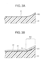
- a bulge RD easily occurs at the outer circumferential ends of a disk substrate 30 formed by injection molding.
- the optical recording layer 31 is formed along the surface of the bulge RD.
- the protection layer film is bonded at the upper layer thereof by an adhesive layer to form the protection layer 32, as shown in FIG. 3B, an air bubble layer AL ends up occurring between the protection layer 32 and the optical recording layer 31, so use of the outer circumferential region RG becomes difficult.
- Disk substrates for optical disks were produced by the above injection molding and were examined for planarity.
- the disk substrates formed had the shape shown in FIG. 4A to 4C, where FIG. 4A is a plan view of a signal surface, FIG. 4B is a side view thereof, and FIG. 4C is a plan view of a read surface.
- FIG. 5A is a view showing the measurement results of the planarity in the vicinity of an outer circumferential end of a signal surface of the disk substrate according to the conventional method.
- the abscissa denotes a position on the disk X (mm), and the ordinate denotes a height of the surface Y ( ⁇ m).
- FIG. 5B is a view showing the measurement results of the planarity in the vicinity of an outer circumferential end of a read surface of the disk substrate according to the conventional method.
- the abscissa denotes a position on the disk X (mm), while the ordinate denotes a height of the surface Y( ⁇ m).
- FIG. 6A is a view showing the measurement results of the planarity in the vicinity of the outer circumferential end of a signal surface of a disk substrate formed by adjusting the pressure for injecting molten resin in the conventional method.
- the abscissa denotes a position on the disk X (mm), while the ordinate denotes a height of the surface Y ( ⁇ m).
- FIG. 6B is a view showing the measurement results of the planarity in the vicinity of an outer circumferential end of a read surface of a disk substrate formed while adjusting the pressure for injecting molten resin in the conventional method.
- the abscissa denotes a position on the disk X (mm), while the ordinate denotes a height of the surface Y ( ⁇ m).
- FIGS. 7A and 7B are views showing the measurement results of the planarity in the vicinity of the innermost diameter A of the signal surface of the disk substrate according to the conventional method divided into two sections.
- the abscissa denotes a position on the disk X (mm), while the ordinate denotes a height of the surface Y ( ⁇ m).
- FIGS. 8A and 8B are views showing the measurement results of the planarity in the vicinity of the innermost diameter A of the read surface of the disk substrate according to the conventional method divided into two sections.
- the abscissa denotes a position on the disk X (mm), while the ordinate denotes a height of the surface Y ( ⁇ m).
- An object of the present invention is to provide a method of a method of producing an information recording medium enabling production of disk substrate, etc. at a high productivity and enhanced planarity in an optical disk or other information recording medium, and to provide a production apparatus for producing the same and a information recording medium produced by such a method of producing.
- the method of producing an information recording medium of the present invention comprises steps of: processing a surface of a disk substrate by satin-like finishing, heating and pressing the disk substrate through compression using a stamper having relief shapes so as to transfer the relief shapes to at least one satin-like finished surface of the disk substrate, forming a recording layer on the relief shape surface of the disk substrate, and forming a coating layer on the recording layer.
- a surface of a disk substrate is processed by satin-like finishing in advance, then the disk substrate is heated and pressed through compression using a stamper having relief shapes so as to transfer the relief shapes to at least one satin-like finished surface of the disk substrate.
- a recording layer is formed on the relief shape surface of the disk substrate, and a coating layer is formed on the recording layer.
- the method of producing an information recording medium of the present invention comprises steps of: processing a surface of a disk substrate by satin-like finishing, heating and pressing the disk substrate through compression using a stamper having relief shapes so as to transfer the relief shapes to at least one satin-like finished surface of the disk substrate, forming a first optical recording layer on the relief shape surface of the disk substrate, processing a surface of a resin sheet by satin-like finishing, heating and pressing the resin sheet through compression using a stamper having relief shapes so as to transfer the relief shapes to at least one satin-like finished surface of the resin sheet, forming a second optical recording layer on the relief shape surface of the resin sheet, bonding the first optical recording layer and the second optical recording layer.
- a surface of a disk substrate is processed by satin-like finishing in advance, then the disk substrate is heated and pressed through compression using a stamper having relief shapes so as to transfer the relief shapes to at least one satin-like finished surface of the disk substrate.
- a first optical recording layer is formed on the relief shape surface of the disk substrate.
- a surface of a resin sheet is processed by satin-like finishing in advance, then the resin sheet is heated and pressed through compression using a stamper having relief shapes so as to transfer the relief shapes to at least one satin-like finished surface of the resin sheet.
- a second optical recording layer is formed on the relief shape surface of the resin sheet.
- the first optical recording layer and the second optical recording layer are bonded.
- the production apparatus for an information recording medium of the present invention is a production apparatus for forming a substrate having relief shapes on at least one surface thereof of an information recording medium comprising the substrate and a recording layer formed on the relief shape surface of the substrate, the production apparatus of an information recording medium comprising: a mold for a compression molding having on an inside surface of a cavity thereof a stamper having relief shapes corresponding to the relief shapes, a heating means for heating the mold, and a pressing means for pressing the mold, the mold being split into an upper, center, and lower parts and being attached to a press movable vertically by the pressing means, a means for correcting parallelism of the lower mold and the upper mold of the press at the time of pressing of the press and making a pressing force uniform between the lower mold and upper mold being provided.
- the mold for a compression molding having on an inside surface of a cavity thereof a stamper having relief shapes corresponding to the relief shapes, is split into an upper, center, and lower parts and is attached to a press movable vertically by the pressing means, and a means for correcting parallelism of the lower mold and the upper mold of the press at the time of pressing of the press and making a pressing force uniform between the lower mold and upper mold is provided.
- the information recording medium of the present invention comprises a disk substrate having relief shapes on at least one surface thereof, a recording layer formed on the relief shape surface of the disk substrate, and a coating layer formed on the recording layer, the disk substrate being a disk substrate processed by a satin-like finishing of the surface thereof, then transferred with the relief shapes to the satin-like finished surface thereof by heating and pressing through compression molding using a stamper having relief shapes.
- a recording layer and a coating layer are formed on the relief shape surface of the disk substrate which is processed by a satin-like finishing of the surface thereof, then transferred with the relief shapes to the satin-like finished surface thereof by heating and pressing through compression molding using a stamper having relief shapes.
- the information recording medium of the present invention comprises a disk substrate having relief shapes on at least one surface thereof, a first optical recording layer formed on the relief shape surface of the disk substrate, a resin sheet having relief shapes on at least one surface thereof, a second optical recording layer formed on the relief shape surface of the disk substrate, the first optical recording layer and the second optical recording layer being bonded, and light being focused from the resin sheet side for the disk substrate to the first optical recording layer and the second optical recording layer to record or reproduce information, wherein the disk substrate being a disk substrate processed by a satin-like finishing of the surface thereof, then transferred with the relief shapes to the satin-like finished surface thereof by heating and pressing through compression molding using a stamper having relief shapes, the resin sheet being a resin sheet processed by a satin-like finishing of the surface thereof, then transferred with the relief shapes to the satin-like finished surface thereof by heating and pressing through compression molding using a stamper having relief shapes.
- a first optical recording layer is formed on the relief shape surface of the disk substrate which is processed by a satin-like finishing of the surface thereof, then transferred with the relief shapes to the satin-like finished surface thereof by heating and pressing through compression molding using a stamper having relief shapes
- a second optical recording layer is formed on the relief shape surface of the resin sheet which is processed by a satin-like finishing of the surface thereof, then transferred with the relief shapes to the satin-like finished surface thereof by heating and pressing through compression molding using a stamper having relief shapes, and the first optical recording layer and the second optical recording layer is bonded.
- FIG. 9A is a schematic perspective view of an optical disk according to the present embodiment.
- An optical disk DC forms an approximately disk shape with a center hole CH formed at a center portion thereof and is driven to rotate in a drive direction DR.
- light LT such as a laser light of a blue to blue-violet color region is focused on an optical recording film in the optical disk DC by an objective lens OL having a numerical aperture of for example 0.8 or greater.
- FIG. 9B is a schematic sectional view of the above optical disk.
- An optical recording layer RL is formed on one surface of a disk substrate Sub having a thickness of about 1.1 mm comprised of polycarbonate resin etc. Further, a light transmitting protection layer (coating layer) PT having a film thickness of about 0.1 mm is formed at the upper layer of the optical recording layer RL.
- light LT such as laser light is focused by an objective lens to the optical recording layer RL from the light transmitting protection layer PT side.
- the returned light reflected at the optical recording layer RL is received at a light-receiving element, a predetermined signal is generated by a signal processing circuit, and a reproduction signal is extracted.
- FIG. 10 is a sectional view of the key portions of an optical disk shown in FIGS. 9A and 9B.
- Relief shapes for dividing track regions are provided in one surface of a disk substrate 10 (Sub) formed of polycarbonate resin etc.
- An optical recording layer 11 (RL) is formed on this surface.
- a light transmitting protection layer (coating layer) 12 (PT) comprised of for example an adhesive layer 12a and a polycarbonate resin sheet 12b is formed on the optical recording layer 11.
- a surface of the disk substrate 10s formed of polycarbonate resin etc. is processed to satin-like finished surface S.
- the process for satin-like finished surface can be performed using later explained apparatuses.
- the maximum surface roughness Rmax of the satin-like finished surface is less than 50 ⁇ m.
- the disk substrate is heated and pressed through compression molding using a stamper (not illustrated) having relief shapes so as to transfer the relief shapes to one satin-like finished surface of the disk substrate 10s.
- the compression molding process can be performed using later explained apparatuses.
- a disk substrate 10 formed with relief shapes containing projecting portions 10a in one surface thereof is obtained.
- satin-like finished shapes have not been left, but the surfaces become mirror surfaces expect for having relief shapes.
- optical recording layer 11 is formed on the relief shapes surface of the disk substrate 10.
- the optical recording layer 11 is for example stacked films of a dielectric film, a recording film, another dielectric film, and a reflection film.
- phase change recording materials or magneto-optical recording materials can be used as the recording firm.
- polycarbonate resin sheet 12b is bonded to the optical recording layer 11 by adhesive layer 12a formed of ultraviolet curing resin etc. and the adhesive layer 12a is cured by irradiation of ultraviolet ray to form the light transmitting protection layer (coating layer) 12.
- the optical disk shown in FIG. 10 can thus be produced.
- a disk substrate for forming an optical disk can be obtained by processing a disk substrate by satin-like finishing of the surface thereof, then heating and pressing it by compression molding using stampers having relief shapes to transfer the relief shapes to the processed surface by satin-like finishing, whereby it is possible to produce with higher productivity a disk substrate having enhanced planarity without burrs or step differences or bulges at the disk outer circumferential portion as in a conventional injection molded substrate. Further, because compression molding is performed after processing the surface of the disk substrate by satin-like finishing, the way of escape of air can be kept in the compression molding, so that air bubble does not retain in the resin and good molding can be performed.
- the disk substrate can be processed sufficiently when the only outermost layer of the disk substrate is heated and pressed, therefore cooling time for the processed object and the mold is short and production efficiency can be raised.
- the optical disk according to the present embodiment differs from the optical disk according to the first embodiment in that a plurality of optical recording layers are stacked.
- FIG. 12 is a schematic sectional view of the optical disk according to the present embodiment wherein two optical recording layers are stacked.
- Relief shapes for dividing track regions are provided in one surface of a disk substrate 10 (Sub) having a thickness of about 1.1 mm formed of polycarbonate resin etc.
- the first optical recording layer 11a is formed on this surface.
- relief shapes for dividing track regions are provided in one surface of a resin sheet 13 having a thickness of about 0.1 mm and being light transmitting protection layer.
- the second optical recording layer 11b is formed on this surface.
- the first optical recording layer 11a and the second optical recording layer 11b are bonded by adhesive layer 14.
- an application to an optical disk having a structure wherein three optical recording layers are stacked is also possible.
- the optical disk of this structure differs from the optical disk shown in FIG. 12 in that the second optical recording layer 11b and the third optical recording layer 11c are formed on the both sides of the disk substrate respectively, and a light transmitting protection layer (coating layer) 17 (PT) comprised of for example a bonding layer 17a and a polycarbonate resin sheet 17b is formed on the third optical recording layer 11c.
- a light transmitting protection layer (coating layer) 17 (PT) comprised of for example a bonding layer 17a and a polycarbonate resin sheet 17b is formed on the third optical recording layer 11c.
- a surface of the disk substrate 10 is processed to satin-like finished surface S, then the disk substrate 10 is heated and pressed through compression molding using a stamper having relief shapes so as to transfer the relief shapes to one satin-like finished surface of the disk substrate 10, and the first optical recording layer 11a is formed on this surface.
- a surface of the resin sheet 13s formed of polycarbonate resin etc. is processed to satin-like finished surface S.
- the process for satin-like finished surface can be performed using later explained apparatuses.
- the surface roughness of the satin-like finished surface is made similar to the disk substrate of the first embodiment.
- the resin sheet is heated and pressed through compression molding using a stamper (not illustrated) having relief shapes so as to transfer the relief shapes to one satin-like finished surface of the resin sheet 13s.
- the compression molding process can be performed using later explained apparatuses.
- the second optical recording layer 11b is formed on the relief shapes surface of the resin sheet 13.
- the first optical recording layer 11a and the second optical recording layer 11b are bonded by an adhesive layer 14 formed of ultraviolet curing resin etc. and the adhesive layer 14 is cured by an irradiation of ultraviolet ray.
- the optical disk shown in FIG. 12 can thus be produced.
- a surface of the disk substrate 10 is processed to satin-like finished surface S, then the disk substrate 10 is heated and pressed through compression molding using a stamper having relief shapes so as to transfer the relief shapes to one satin-like finished surface of the disk substrate 10, and the first optical recording layer 11a is formed on this surface.
- a surface of the resin sheet 15s formed of polycarbonate resin etc. is processed to satin-like finished surface S.
- the process for satin-like finished surface can be performed using later explained apparatuses.
- the resin sheet is heated and pressed through compression molding using a stamper (not illustrated) having relief shapes so as to transfer the relief shapes to both satin-like finished surfaces of the resin sheet 15s.
- the compression molding process can be performed using later explained apparatuses.
- the second optical recording layer 11b is formed on the relief shapes surface of one surface of the resin sheet 15, and the third optical recording layer 11c is formed on the relief shapes surface of the other surface of the resin sheet 15.
- the first optical recording layer 11a and the second optical recording layer 11b are bonded by an adhesive layer 16 formed of ultraviolet curing resin etc. and the adhesive layer 16 is cured by an irradiation of ultraviolet ray.
- polycarbonate resin sheet 17b is bonded to the third optical recording layer 11c by adhesive layer 17a formed of ultraviolet curing resin etc. and the adhesive layer 17a is cured by irradiation of ultraviolet ray to form the light transmitting protection layer (coating layer) 17.
- the optical disk shown in FIG. 13 can thus be produced.
- a disk substrate and a resin sheet for forming an optical disk can be obtained by processing a disk substrate and a resin sheet by satin-like finishing of the surface thereof, then heating and pressing them by compression molding using stampers having relief shapes to transfer the relief shapes to the processed surface by satin-like finishing, whereby it is possible to produce with higher productivity a disk substrate having enhanced planarity without burrs or step differences or bulges at the disk outer circumferential portion as in a conventional injection molded substrate. Further, because compression molding is performed after processing the surface of the disk substrate by satin-like finishing, the way of escape of air can be kept in the compression molding, so that air bubble does not retain in the resin and good molding can be performed.
- the disk substrate and the resin sheet can be processed sufficiently when the only outermost layer of the disk substrate and the resin sheet are heated and pressed, therefore cooling time for the processed objects and the mold is short and production efficiency can be raised.
- optical recording layers except for the lowermost optical recording layer need to be made translucent.
- the reflectance of the second optical recording layer 11b is set to about 30% and the reflectance of the third optical recording layer 11c is set to about 19%.
- data can be accurately recorded on and reproduced from each of the optical recording layers without disturbing the recording or reproduction of data on or from the lower optical recording layer.
- These reflectances may be adjusted by sequentially reducing the thickness of the reflection films, comprised of aluminum or silver and alloys thereof, forming the translucent films in the optical recording layers toward the uppermost layer.
- An information recording medium is a discrete type hard disk obtained by sheet molding.
- the compression molding method shown in the first embodiment is applied to a disk substrate of the hard disk.
- FIG. 16 is a schematic sectional view of a one-sided structure hard disk apparatus according to the present embodiment.
- Relief shapes 20a for imparting a servo signal are formed on one surface of a disk substrate 20, a magnetic film 21 is formed over the entire surface thereof, and a silicone oil or other lubricant layer 22 is formed thereon as a coating layer.
- signals are recorded on or reproduced from the magnetic films 21 by a floating magnetic head MH at the tip of a slider SL.
- FIG. 17 is a schematic sectional view of a two-sided structure hard disk apparatus according to the present embodiment.
- Relief shapes 23a for imparting a servo signal are formed on a top surface of a disk substrate 23, the first magnetic film 24 is formed over the entire surface thereof, and a silicone oil or other lubricant layer 26 is formed thereon as a coating layer.
- relief shapes 23b for imparting a servo signal are formed on a bottom surface of the disk substrate 23, the second magnetic film 25 is formed over the entire surface thereof, and a silicone oil or other lubricant layer 27 is formed thereon as a coating layer.
- signals are recorded on or reproduced from the first and second magnetic films (24, 25) by a floating magnetic head MH at the tip of a slider SL.
- a surface of the disk substrate 20s formed of an amorphous polyolefin resin etc. slightly thicker than the desired thickness of 0.2 mm to 1.2 mm is processed to satin-like finished surface S.
- the process for satin-like finished surface can be performed using later explained apparatuses.
- the surface roughness of the satin-like finished surface is made similar to the disk substrate of the first embodiment.
- the disk substrate is heated and pressed through compression molding using a stamper (not illustrated) having relief shapes so as to transfer the relief shapes to one satin-like finished surface of the disk substrate 20s.
- the compression molding process can be performed using later explained apparatuses.
- a disk substrate 20 formed with relief shapes containing projecting portions 20a in one surface thereof is obtained.
- satin-like finished shapes have not been left, but the surfaces become mirror surfaces expect for having relief shapes.
- films made of a magnetic material such as Pt-Co are formed on relief shapes 20a forming surface of the disk substrate by for example sputtering to thereby form the magnetic layers 21.
- silicone oil or another lubricant is coated to a film thickness of 10 ⁇ m or less to thereby form the lubricant layers 22.
- the hard disk shown in FIG. 16 can thus be formed.
- a surface of the disk substrate 23s formed of an amorphous polyolefin resin etc. slightly thicker than the desired thickness of 0.2 mm to 1.2 mm is processed to satin-like finished surface S.
- the disk substrate is heated and pressed through compression molding using a stamper (not illustrated) having relief shapes so as to transfer the relief shapes to both satin-like finished surfaces of the disk substrate 23s.
- a disk substrate 23 formed with relief shapes containing projecting portions (23a, 23b) in both surfaces thereof is obtained.
- satin-like finished shapes have not been left, but the surfaces become mirror surfaces expect for having relief shapes.
- films made of a magnetic material such as Pt-Co are formed on the top surface and the bottom surface of the disk substrate by for example sputtering to thereby form the first magnetic layer 24 and the second magnetic layer25.
- silicone oil or another lubricant is coated to a film thickness of 10 ⁇ m or less to thereby form the lubricant layers (26, 27).
- the hard disk shown in FIG. 17 can thus be formed.
- the disk substrate formed in this way enables the production of a disk substrate having a surface of enhanced planarity free from the bulge or recesses at the outer circumferential region distinctive to a one-sided or two-sided disk obtained by injection molding and free from the fine step differences due to the mold release or stamper guides at the inner circumference unavoidable in injection molded disks and step differences at the parting surface distinctive to an assembled mold.
- FIG. 20 is a schematic view of the configuration of a compression molding apparatus for pressing and hot pressing a light transmitting resin sheet (thickness of 10 ⁇ m to 100 ⁇ m) or a disk substrate (thickness of 0.2 mm to 2.0 mm) to transfer a relief pattern of the stamper thereto in the present embodiment.
- a compression molding apparatus 100a has a press upper platen 101, an upper heating platen 102, an upper mold 103, a heat release sheet 104, a center mold guide 105, a first center mold 106, a stopper 107, a vacuum hole 108, a first stamper 109, a second stamper 110, a second center mold 111, a stopper 112, a heat release sheet 113, a lower mold 114, a lower heating platen 115, a press lower platen 116, and a hydraulic ram 117.
- the above compression molding apparatus 100a is a three molding clamping speed, 30-ton automatic hydraulic press which has a position control mechanism.
- the upper and lower molds (103, 114) are fixed to the heating platens of the press.
- the center mold is structured to be able to be further divided into two.
- the inside of the cavity can be evacuated.
- a resin sheet or a disk substrate 120 is clamped by the two stampers (109, 110) in the above cavity and then pressed and heated by heaters (upper heating platen 102 and lower heating platen 115) for heating the upper and lower molds respectively to a temperature 5°C to 50°C higher than the glass transition temperature of the resin sheet or the disk substrate 120 to thereby transfer the relief shapes of the stampers (109, 110) to the resin sheet or the disk substrate 120.
- heaters upper heating platen 102 and lower heating platen 115
- the upper heating platen 102 is attached to the press upper platen 101 of the press 100a moved up and down by the hydraulic ram 117 etc., the upper mold 103 having a flat surface is further fixed thereto, and heat release sheet 104 of thickness of 2 mm or less, that is, an elastic member having good heat conduction, is bonded to the surface of the upper mold 103.
- the elastic member functions to absorb deviations in parallelism accompanying repeated up and down movement of the hydraulic ram 117 or heat expansion occurring at the time of heating the heating platen and deviations in parallelism of the upper, center, and lower molds themselves so as to enable the entire surface of the mold to be uniformly pressed.
- an elastic member generally acts as a thermal insulator, so if it is not made as thin as possible to enable the mold to be heated through the thermal insulator, there is the drawback that the heat conduction will become poor and the formation time will become longer.
- a heat release sheet of an elastic member containing boron nitride or another material superior in heat conduction (0.4 mm thick, made by Shin-Etsu Silicon Co. Ltd., product name: TC-BG Type).
- FIG. 21 is a schematic view of the configuration of a compression molding apparatus jointly using heating of the center mold by an external heating device in addition to the heating from the heating platens of the press in the compression molding apparatus shown in FIG. 20.
- a near-infrared ray heater unit IL is inserted from the outside in the state where the mold assembly is opened in conjunction with the up and down movement of the molding machine.
- the rest of the configuration is substantially the same as the compression molding apparatus shown in FIG. 20.
- the above near-infrared ray heater unit IL is comprised of a plurality of (for instance 11) for example 1 KW near-infrared ray lamps (the drawing showing the position of the filament FM) arranged at a pitch of 20 mm in a lamp housing HS and is separated from the center mold by a distance of 20 mm to make the irradiation intensity uniform.
- the intensity of the infrared rays (IR) of the above near-infrared ray heater unit IL, as shown in FIG. 22B, is substantially uniform across the size WS of the workpiece WK, that is, the resin film or the resin sheet being processed.
- the above near-infrared ray heater unit IL is inserted between the upper mold 103 and the first center mold 106 and between the second center mold 111 and the lower mold 114 in the state where the mold assembly is opened and rapidly heats the center mold (106, 111) selectively to heat the film or the sheet inside the center mold to a temperature exceeding its glass transition point, however, when the rapid heating is finished, it swiftly is retracted to the outside of the press.
- the hydraulic ram 117 starts to rise to heat and press the same from the upper mold 103 and lower mold 114.
- the surface temperature of the center mold can be raised to from 120°C to 200°C.
- the heating and pressing time of for example nearly 120 seconds required in the direct heating method can be shortened to, for example, 5 seconds or less.
- FIG. 23 and FIG. 24 are schematic views of the center mold part for the compression molding for giving the surface of the resin film or resin sheet a satin-like finish in advance.
- the rest of the structure other than the center mold is substantially the same as that of the compression molding apparatus of FIG. 20.
- a center mold part 50a has a center mold guide 51, a first center mold 52, a vacuum hole 53, a stopper 54, glass fiberfil fluororesin sheets (55a, 56a), an O-ring 57, a second center mold 58, and a stopper 59.
- the resin sheet or the disk substrate 120 is gripped between two glass fiberfil fluororesin sheets (55a, 56a) and compression molded so as to transfer the fine satin-like finish unevenness (for example, the average surface roughness Ra is 25 ⁇ m to 30 ⁇ m.) of the surfaces of the glass fiberfil fluororesin sheets (55a, 56a) and give the surfaces of the resin sheet or the disk substrate 120 a satin-like finish.
- the fine satin-like finish unevenness for example, the average surface roughness Ra is 25 ⁇ m to 30 ⁇ m.
- the above glass fiberfil fluororesin sheets (55a, 56a) are sheets comprised of glass fiber cloth impregnated with a fluororesin or adhesive sheets (for example, Chukoh Chemical Industries Ltd.: AFG-100).
- a center mold part 50b has a center mold guide 51, a first center mold 52, a vacuum hole 53, a stopper 54, satin-like finish plates (55b, 56b), an O-ring 57, a second center mold 58, and a stopper 59.
- the resin sheet or the disk substrate 120 is gripped between the two satin-like finish plates (55b, 56b) and compression molded to transfer the fine satin-like finish unevenness of the surfaces of the satin-like finish plates (55b, 56b) and thereby give the surfaces of the resin sheet or the disk substrate 120 a satin-like finish.
- the above "satin-like finish plates” may be for example SUS304 1.5 mm thick plate sandblasted with SiC or alumina powder (for example, the average surface roughness Ra is 6 ⁇ m to 13 ⁇ m.) or performed with etching treatment (for example, the average surface roughness Ra is 27 ⁇ m to 37 ⁇ m.) on one surface.
- Disk substrates for optical disks were produced by the method of production according to the first embodiment and were examined for planarity.
- the disk substrates being produced have the shapes shown in FIGS. 4A to 4C.
- FIG. 26A to 26D are views showing the measurement results of the planarity in the vicinity of an outer circumferential end of the disk substrate produced by the production method according to the first embodiment.
- the abscissa denotes a position on the disk X (mm), while the ordinate denotes a height of the surface Y ( ⁇ m).
- FIG. 26A, 26B, 26C, and 26D correspond to the measurement results at positions rotated 0 degree, 90 degrees, 180 degrees, and 270 degrees clockwise around the center of the disk from a reference radius position when setting a radius position serving as a reference of the disk. Note that the results are almost the same as those of the signal surface and the read surface.
- both of the occurrence of burrs and step differences such as above in the vicinity of the innermost diameter A was suppressed.
- the present embodiment by gripping a resin sheet or a disk substrate processed to a satin-like finish between two stampers and heating and pressing the same, it is possible to easily obtain a resin sheet or a disk substrate having information signal at the two sides without regard to thickness as compared with conventional formation where mold parts had to be designed, fabricated, and exchanged in order to change the thickness.
- An optical disk of single layer, or an optical disk of multiplayer of a two- to three-layers structure can be formed without the time and expense to fabricate mold parts or the work of exchanging the same.
- any one-sided or two-sided substrate having a thickness of 0.2 mm to 2.0 mm can be formed, the orientation strain at the time of injection and cooling which cannot be achieved in injection molding is extremely small, and a flat disk having no recesses or bulge at the outer circumference or burrs or step differences at the inner and outer circumference can be achieved.
- Application to hard disk media other than optical disks is also possible.
- disks having an extremely small birefringence at both the inner and outer circumferences can also be achieved.
- the resin sheet can be cut into any size, it is easy to handle large to small sized disks without preparing different molds each time. Disks of different thicknesses, which could not be obtained up until now without changing the mold parts, become possible just by changing the thickness of the resin sheet used. The time spent on the design and fabrication of the mold parts is shortened and the mold parts need not be manufactured, so the speed of development and manufacture can be increased and costs cut.
- the present invention is not limited to the above embodiments.
- the optical recording layer is not limited to the layer configuration, the materials, thicknesses, etc. of the magnetic layer or the protection layer or other coating layers described in the above embodiments. These can be suitably selected.
- the materials etc. of the disk substrate are not limited to the above materials. Any material that can be processed into a disk shape by the compression molding process can be used.
- an information recording medium of the present invention in the process of producing the optical disk or other information recording medium, it is possible to produce a disk substrate or a resin sheet having enhanced planarity with high productivity.
- the production apparatus for an information recording medium of the present invention as the production apparatus for optical disk or other information recording medium, it is possible to produce a disk substrate or a resin sheet having enhanced planarity with high productivity.
- an information recording medium wherein a disk substrate or a resin sheet can be produced which has enhanced planarity with high productivity.
Applications Claiming Priority (2)
| Application Number | Priority Date | Filing Date | Title |
|---|---|---|---|
| JP2001333328 | 2001-10-30 | ||
| JP2001333328 | 2001-10-30 |
Publications (2)
| Publication Number | Publication Date |
|---|---|
| EP1308944A2 true EP1308944A2 (de) | 2003-05-07 |
| EP1308944A3 EP1308944A3 (de) | 2007-10-17 |
Family
ID=19148615
Family Applications (1)
| Application Number | Title | Priority Date | Filing Date |
|---|---|---|---|
| EP02024465A Withdrawn EP1308944A3 (de) | 2001-10-30 | 2002-10-29 | Verfahrun zur Herstellung eines Informationsaufzeichnungsmediums, Herstellungsvorrichtung und Informationsaufzeichnungsmedium |
Country Status (5)
| Country | Link |
|---|---|
| EP (1) | EP1308944A3 (de) |
| KR (1) | KR100954470B1 (de) |
| CN (1) | CN1255794C (de) |
| HK (1) | HK1059675A1 (de) |
| SG (1) | SG107119A1 (de) |
Cited By (2)
| Publication number | Priority date | Publication date | Assignee | Title |
|---|---|---|---|---|
| EP1852860A1 (de) * | 2005-02-18 | 2007-11-07 | FUJIFILM Corporation | Optisches aufzeichnungsmedium und herstellungsverfahren dafür, substrat und dessen verwendung, matrize und herstellungsverfahren dafür |
| EP2224444A3 (de) * | 2009-02-11 | 2010-10-13 | Rohm and Haas Electronic Materials, L.L.C. | Optische Datenspeichermedien und Herstellungsgsverfahren |
Families Citing this family (2)
| Publication number | Priority date | Publication date | Assignee | Title |
|---|---|---|---|---|
| KR20090091688A (ko) * | 2006-12-28 | 2009-08-28 | 파나소닉 주식회사 | 정보 기록 매체 평가 방법, 정보 기록 매체, 정보 기록 매체의 제조 방법, 신호 처리 방법, 액세스 제어 장치 |
| EP2221324B1 (de) * | 2009-02-18 | 2013-01-16 | Rohm and Haas Company | Verfahren zur Herstellung von verbesserten aliphatischen Dicarboxylsäure-Copolymeren |
Citations (2)
| Publication number | Priority date | Publication date | Assignee | Title |
|---|---|---|---|---|
| US4288481A (en) * | 1979-07-14 | 1981-09-08 | Emi Limited | Foil video discs |
| US5820794A (en) | 1995-01-24 | 1998-10-13 | Samsung Electronics Co., Ltd. | Multi-layer optical recording medium manufacturing method |
Family Cites Families (12)
| Publication number | Priority date | Publication date | Assignee | Title |
|---|---|---|---|---|
| DE68927617T2 (de) * | 1988-04-27 | 1997-06-05 | Dainippon Ink & Chemicals | Vorrichtung zum Herstellen eines optischen Informations-Aufzeichnungsträgers |
| JPH041926A (ja) * | 1990-04-18 | 1992-01-07 | Mitsubishi Plastics Ind Ltd | 情報記録媒体用スタンパ、情報記録媒体用成形基板およびそれらの製造方法 |
| JPH04149833A (ja) * | 1990-10-12 | 1992-05-22 | Canon Inc | 情報記録媒体及びその製造方法 |
| JPH09320117A (ja) * | 1996-05-28 | 1997-12-12 | Pioneer Electron Corp | 光ディスク |
| JPH1049913A (ja) * | 1996-08-02 | 1998-02-20 | Sony Miyuujitsuku Entertainment:Kk | ライトワンス形プリレコーデッド光ディスクおよびその製造方法 |
| KR19980024169A (ko) * | 1996-09-04 | 1998-07-06 | 가나이 츠토무 | 수직자기기록매체 및 그것을 사용한 자기기록 재생장치 |
| JPH10326435A (ja) * | 1997-03-25 | 1998-12-08 | Sony Corp | 光学記録媒体及び光学ディスク装置 |
| JP2986781B1 (ja) * | 1998-07-15 | 1999-12-06 | 株式会社ソニー・ミュージックエンタテインメント | 光ディスクおよびその製造方法 |
| KR20000033201A (ko) * | 1998-11-20 | 2000-06-15 | 윤종용 | 안정된 신호특성을 얻을 수 있는 광기록매체 |
| JP3643717B2 (ja) * | 1999-01-12 | 2005-04-27 | 株式会社日立製作所 | 光ディスク用基板の製造方法 |
| JP2001167482A (ja) * | 1999-12-08 | 2001-06-22 | Sony Corp | 光学式記録媒体の製造方法及び製造装置 |
| CN1309387A (zh) * | 2000-02-15 | 2001-08-22 | 富士胶片株式会社 | 磁转写用主载体及磁记录媒体 |
-
2002
- 2002-10-29 EP EP02024465A patent/EP1308944A3/de not_active Withdrawn
- 2002-10-29 SG SG200206563A patent/SG107119A1/en unknown
- 2002-10-29 KR KR1020020066014A patent/KR100954470B1/ko not_active IP Right Cessation
- 2002-10-30 CN CNB021542953A patent/CN1255794C/zh not_active Expired - Fee Related
-
2004
- 2004-01-20 HK HK04100454A patent/HK1059675A1/xx not_active IP Right Cessation
Patent Citations (2)
| Publication number | Priority date | Publication date | Assignee | Title |
|---|---|---|---|---|
| US4288481A (en) * | 1979-07-14 | 1981-09-08 | Emi Limited | Foil video discs |
| US5820794A (en) | 1995-01-24 | 1998-10-13 | Samsung Electronics Co., Ltd. | Multi-layer optical recording medium manufacturing method |
Cited By (4)
| Publication number | Priority date | Publication date | Assignee | Title |
|---|---|---|---|---|
| EP1852860A1 (de) * | 2005-02-18 | 2007-11-07 | FUJIFILM Corporation | Optisches aufzeichnungsmedium und herstellungsverfahren dafür, substrat und dessen verwendung, matrize und herstellungsverfahren dafür |
| EP1852860A4 (de) * | 2005-02-18 | 2008-07-02 | Fujifilm Corp | Optisches aufzeichnungsmedium und herstellungsverfahren dafür, substrat und dessen verwendung, matrize und herstellungsverfahren dafür |
| EP2224444A3 (de) * | 2009-02-11 | 2010-10-13 | Rohm and Haas Electronic Materials, L.L.C. | Optische Datenspeichermedien und Herstellungsgsverfahren |
| US8389094B2 (en) | 2009-02-11 | 2013-03-05 | Rohm And Haas Electronic Materials Llc | Optical data storage media and methods of formation |
Also Published As
| Publication number | Publication date |
|---|---|
| KR100954470B1 (ko) | 2010-04-22 |
| CN1255794C (zh) | 2006-05-10 |
| KR20030035986A (ko) | 2003-05-09 |
| HK1059675A1 (en) | 2004-07-09 |
| CN1433009A (zh) | 2003-07-30 |
| SG107119A1 (en) | 2004-11-29 |
| EP1308944A3 (de) | 2007-10-17 |
Similar Documents
| Publication | Publication Date | Title |
|---|---|---|
| US6764737B2 (en) | Method of producing information recording medium, production apparatus and information recording medium | |
| US7731871B2 (en) | Optical disk and method for producing the same | |
| US7161893B2 (en) | Stamper for fabrication of optical recording medium, method of forming information recording area and light transmissive layer, and optical recording medium | |
| JP4066489B2 (ja) | 光記録媒体及びその製造方法 | |
| EP1308944A2 (de) | Verfahrun zur Herstellung eines Informationsaufzeichnungsmediums, Herstellungsvorrichtung und Informationsaufzeichnungsmedium | |
| EP1192034B1 (de) | Verfahren zur herstellung einer optischen platte mit reduziertem kantenkeil | |
| US7187644B2 (en) | Optical recording substrate, optical recording medium, and manufacturing method thereof | |
| JP2009129486A (ja) | 情報記録媒体基板製造方法 | |
| JP2003296978A (ja) | 光学記録媒体の製造方法および光学記録媒体 | |
| JP2009043330A (ja) | 光ディスクの製造方法 | |
| JP2001189034A (ja) | 光記録媒体及びその製造方法 | |
| JP4228801B2 (ja) | 記録媒体基板、記録媒体と、これらの製造方法および記録媒体基板の成型装置 | |
| WO2002067251A1 (fr) | Support d'enregistrement optique et son procede de production | |
| JPH08124223A (ja) | 光ディスクの製造方法 | |
| JP2005063524A (ja) | 光ディスク及びその製造方法 | |
| JP2008217932A (ja) | 光ディスクの製造方法 | |
| JP4519554B2 (ja) | 光ディスク及びその製造方法 | |
| JPH0227539A (ja) | 光ディスク基板およびその製造方法 | |
| JP2000348384A (ja) | 多層光ディスク、その製造方法および反射膜形成装置 | |
| JP2007323769A (ja) | 光記録媒体の製造方法 | |
| JP2001357561A (ja) | 光ディスク及びその製造方法 | |
| JP2005243114A (ja) | 転写装置、転写方法および情報記録媒体 | |
| JP2010080033A (ja) | 光ディスク及び光ディスクの製造方法 | |
| JPH08124222A (ja) | 光ディスクの製造方法 | |
| JP2005329670A (ja) | ディスク基板成形用金型装置およびディスク基板成形方法 |
Legal Events
| Date | Code | Title | Description |
|---|---|---|---|
| PUAI | Public reference made under article 153(3) epc to a published international application that has entered the european phase |
Free format text: ORIGINAL CODE: 0009012 |
|
| AK | Designated contracting states |
Designated state(s): AT BE BG CH CY CZ DE DK EE ES FI FR GB GR IE IT LI LU MC NL PT SE SK TR |
|
| AX | Request for extension of the european patent |
Extension state: AL LT LV MK RO SI |
|
| PUAL | Search report despatched |
Free format text: ORIGINAL CODE: 0009013 |
|
| AK | Designated contracting states |
Kind code of ref document: A3 Designated state(s): AT BE BG CH CY CZ DE DK EE ES FI FR GB GR IE IT LI LU MC NL PT SE SK TR |
|
| AX | Request for extension of the european patent |
Extension state: AL LT LV MK RO SI |
|
| 17P | Request for examination filed |
Effective date: 20080319 |
|
| 17Q | First examination report despatched |
Effective date: 20080428 |
|
| AKX | Designation fees paid |
Designated state(s): AT DE FR GB NL |
|
| STAA | Information on the status of an ep patent application or granted ep patent |
Free format text: STATUS: THE APPLICATION IS DEEMED TO BE WITHDRAWN |
|
| 18D | Application deemed to be withdrawn |
Effective date: 20130925 |