BACKGROUND OF THE INVENTION
1. Field of the Invention
The present invention relates to a method of
producing an information recording medium, a production
apparatus for the information recording medium, and an
information recording medium produced by the production
method.
2. Description of the Related Art
Recently, in the field of information recording,
research on optical information recording systems is
being conducted everywhere.
Optical information recording systems have numerous
advantages such as the capability of non-contact
recording and reproduction and the ability to handle
various forms of memories such as read only types, write-once
types, and rewritable types. Broad applications from
industrial use to consumer use are being considered as
systems enabling realization of inexpensive and large
size files.
Increased capacity of optical recording media
(hereinafter also referred to "optical disks") for the
above various types of optical information recording
systems has been achieved mainly by shortening the
wavelength of the laser light serving as the light source
used in optical information recording systems and
adopting objective lenses having high numerical apertures
to reduce the spot size on a focal plane.
For example, in a CD (compact disk), the thickness
of the disk substrate forming a light transmitting layer
is about 1.2 mm, the wavelength of the laser light is 780
nm, the numerical aperture (NA) of the objective lens is
0.45, and the capacity is 650 MB, while in a DVD-ROM
(digital versatile disk read-only memory), the thickness
of the disk substrate forming a light transmitting layer
is about 0.6 mm, the wavelength of the laser light is 650
nm, the NA is 0.6, and the capacity is 4.7 GB. A DVD is
for example obtained by bonding together two disk
substrate of about 0.6 mm thickness to form a disk having
a thickness of 1.2 mm.
Furthermore, in the next generation optical disk
systems, it is possible to increase the capacity to 22 GB
or more by using an optical disk comprising an optical
recording layer over which is formed a protection layer,
that is, a light transmitting coating layer, reduced in
thickness to about 0.1 mm, and making the laser light
wavelength 450 nm or less and the NA 0.78 or greater.
FIG. 1A is a schematic perspective view of an
optical disk for the above next generation optical disk
system.
An optical disk DC forms an approximately disk
shape with a center hole CH formed at a center portion
thereof and is driven to rotate in a drive direction DR.
When recording or reproducing information, light LT
such as a laser light of a blue to blue-violet color
region is focused on the optical recording film in the
optical disk DC by an objective lens OL having a
numerical aperture of for example 0.8 or greater.
FIG. 1B is a schematic sectional view of the above
optical disk.
Grooves for dividing track regions are provided in
one surface of a disk substrate 30 having a thickness of
about 1.1 mm formed of polycarbonate resin etc. An
optical recording layer 31 comprised of for example a
reflection film, a dielectric film, a recording film,
another dielectric film, etc. stacked in that order is
formed on this surface. The layer configuration and the
number of layers of the optical recording layer 31 differ
according to the type of recording material and the
design.
The above recording film is for example a phase
change type recording film, a magneto-optical recording
film, or a recording film containing an organic dye.
Further, a light transmitting protection layer
(coating layer) 32 having a film thickness of 0.1 mm
comprised of for example an adhesive layer and a polymer
film is formed on the optical recording layer 31.
When recording on or reproducing from the above
optical disk, light LT such as laser light is focused by
the objective lens OL to the optical recording layer 31
from the protection layer 32 side.
At the time of reproduction from the optical disk,
returned light reflected at the optical recording layer
31 is received by a light-receiving element, a
predetermined signal is generated by a signal processing
circuit, and a reproduction signal is extracted.
A production method of the above optical disk shown
in FIGS. 1A and 1B will be explained next.
First, for example, a disk substrate 30 comprised
of for example polycarbonate resin is formed by injection
molding using injection mold described below having a
stamper for disk substrate which has a relief pattern for
optical recording layer.
Next, an optical recording layer 31 is formed on
the disk substrate.
Next, polycarbonate film is bonded to the optical
recording layer 31 by adhesive layer to form the light
transmitting protection layer (coating layer) 32 of 0.1
mm thickness.
The optical disk shown in FIGS. 1A and 1B can thus
be formed.
FIG. 2 is a schematic view of the configuration of
an injection molding mold for forming a disk substrate
according to a conventional method.
An outer circumferential ring 61, a fixed side
mirror 62, a fixed side temperature adjusting circuit 63,
a stamper 64, and a sprue 65 are provided as fixed side
mold parts at a fixed side attachment plate FT. On the
other hand, a movable side mirror 67, a center pin 68,
and a gate cut punch 69 are provided as movable side mold
parts in movable side attachment plate MT. Resin is
injected into a cavity 66 composed of the above parts to
form a disk substrate.
However, in information recording medium including
CDs, DVDs, and other optical disks, including next
generation optical disks of the above configuration, and
further hard disks, the disk substrates are generally
formed by injection molding. In this case, however, a
mold for the injection molding is configured by a
plurality of parts. Clearance is inevitable between the
parts. Therefore, burrs occur in the disk substrate
formed.
Further, it is difficult to achieve a uniform
surface precision of the parts or stamper. If step
differences occur between the parts, the steps will also
end up being transferred to the disk substrate formed.
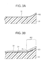
Further, as shown in FIG. 3A, a bulge RD easily
occurs at the outer circumferential ends of a disk
substrate 30 formed by injection molding. In this case,
the optical recording layer 31 is formed along the
surface of the bulge RD.
If for example the protection layer film is bonded
at the upper layer thereof by an adhesive layer to form
the protection layer 32, as shown in FIG. 3B, an air
bubble layer AL ends up occurring between the protection
layer 32 and the optical recording layer 31, so use of
the outer circumferential region RG becomes difficult.
Even when coating ultraviolet curing resin or other
protection layer on the optical recording layer by spin
coating, etc., the bulge of the outer circumferential end
region is further accentuated and therefore it becomes
impossible to use this region.
By adjusting the pressure for injecting the molten
resin so as to suppress the occurrence of the bulge in
the injection molding of the disk substrate, a recess
where part of the substrate becomes thinner easily occurs
and hence a new problem arises.
Disk substrates for optical disks were produced by
the above injection molding and were examined for
planarity.
Here, the disk substrates formed had the shape
shown in FIG. 4A to 4C, where FIG. 4A is a plan view of a
signal surface, FIG. 4B is a side view thereof, and FIG.
4C is a plan view of a read surface.
In the figure, the positions of an innermost
diameter (A), a sprue bushing (B), an air groove (C), a
stamper holder (D), a signal portion (stamper) (E), an
ejector (F), an ejector sleeve guide (G), a stacking rib
(H), a mirror (I), and an outer circumferential end (Z)
are shown.
FIG. 5A is a view showing the measurement results
of the planarity in the vicinity of an outer
circumferential end of a signal surface of the disk
substrate according to the conventional method. The
abscissa denotes a position on the disk X (mm), and the
ordinate denotes a height of the surface Y (µm).
This shows the occurrence of a bulge RD at the
vicinity of the outer circumferential end Z.
FIG. 5B is a view showing the measurement results
of the planarity in the vicinity of an outer
circumferential end of a read surface of the disk
substrate according to the conventional method. The
abscissa denotes a position on the disk X (mm), while the
ordinate denotes a height of the surface Y(µm).
This shows the occurrence of a burr BR and bulge RD
at the vicinity of the outer circumferential end Z.
FIG. 6A is a view showing the measurement results
of the planarity in the vicinity of the outer
circumferential end of a signal surface of a disk
substrate formed by adjusting the pressure for injecting
molten resin in the conventional method. The abscissa
denotes a position on the disk X (mm), while the ordinate
denotes a height of the surface Y (µm).
The bulge RD in the vicinity of the outer
circumferential end Z is suppressed, however, a recess RS
where the disk becomes thinner occurs.
FIG. 6B is a view showing the measurement results
of the planarity in the vicinity of an outer
circumferential end of a read surface of a disk substrate
formed while adjusting the pressure for injecting molten
resin in the conventional method. The abscissa denotes a
position on the disk X (mm), while the ordinate denotes a
height of the surface Y (µm).
The bulge RD in the vicinity of the outer
circumferential end Z is suppressed, however, a recess RS
where the disk becomes thinner occurs.
FIGS. 7A and 7B are views showing the measurement
results of the planarity in the vicinity of the innermost
diameter A of the signal surface of the disk substrate
according to the conventional method divided into two
sections. The abscissa denotes a position on the disk
X (mm), while the ordinate denotes a height of the surface
Y (µm).
Occurrence of a burr (BR) and step difference (ST)
was seen at an interface of the stamper holder (D) and
the signal portion (stamper) (E). Further, a burr (BR)
occurred at the innermost diameter A end or the like.
FIGS. 8A and 8B are views showing the measurement
results of the planarity in the vicinity of the innermost
diameter A of the read surface of the disk substrate
according to the conventional method divided into two
sections. The abscissa denotes a position on the disk
X (mm), while the ordinate denotes a height of the surface
Y (µm).
At an interface of the ejector sleeve guide (G) and
the mirror (I), occurrence of a slight burr (BR) and step
difference (ST) was seen. Further, a step difference (ST)
occurred at an interface of the ejector (F) and the
ejector sleeve guide (G).
The method of forming a disk substrate by a
compression molding is known. However, there is a problem
that it needs long process time because resin is heated
and made molten by mold and cooled after compression
molding in the compression molding method.
Further, it is difficult to remove gas from resin
in the time of compression molding, and vacuum exhaust is
performed but it is not sufficient, therefore there is a
problem that shape of the disk substrate becomes bad due
to retaining air bubble in the resin.
Further, in a hard disk, bulge is formed when the
injection molding is performed as well as the disk
substrate of the optical disk, therefore the magnetic
head floating with a clearance of several tens of nm ends
up striking the surface of the hard disk due to this
bulge.
SUMMARY OF THE INVENTION
An object of the present invention is to provide a
method of a method of producing an information recording
medium enabling production of disk substrate, etc. at a
high productivity and enhanced planarity in an optical
disk or other information recording medium, and to
provide a production apparatus for producing the same and
a information recording medium produced by such a method
of producing.
To achieve the above object, the method of
producing an information recording medium of the present
invention comprises steps of: processing a surface of a
disk substrate by satin-like finishing, heating and
pressing the disk substrate through compression using a
stamper having relief shapes so as to transfer the relief
shapes to at least one satin-like finished surface of the
disk substrate, forming a recording layer on the relief
shape surface of the disk substrate, and forming a
coating layer on the recording layer.
In the above method of producing an information
recording medium, a surface of a disk substrate is
processed by satin-like finishing in advance, then the
disk substrate is heated and pressed through compression
using a stamper having relief shapes so as to transfer
the relief shapes to at least one satin-like finished
surface of the disk substrate. Next, a recording layer is
formed on the relief shape surface of the disk substrate,
and a coating layer is formed on the recording layer.
Further, to achieve the above object, the method of
producing an information recording medium of the present
invention comprises steps of: processing a surface of a
disk substrate by satin-like finishing, heating and
pressing the disk substrate through compression using a
stamper having relief shapes so as to transfer the relief
shapes to at least one satin-like finished surface of the
disk substrate, forming a first optical recording layer
on the relief shape surface of the disk substrate,
processing a surface of a resin sheet by satin-like
finishing, heating and pressing the resin sheet through
compression using a stamper having relief shapes so as to
transfer the relief shapes to at least one satin-like
finished surface of the resin sheet, forming a second
optical recording layer on the relief shape surface of
the resin sheet, bonding the first optical recording
layer and the second optical recording layer.
In the above method of producing an information
recording medium, a surface of a disk substrate is
processed by satin-like finishing in advance, then the
disk substrate is heated and pressed through compression
using a stamper having relief shapes so as to transfer
the relief shapes to at least one satin-like finished
surface of the disk substrate. Next, a first optical
recording layer is formed on the relief shape surface of
the disk substrate. On the other hand, a surface of a
resin sheet is processed by satin-like finishing in
advance, then the resin sheet is heated and pressed
through compression using a stamper having relief shapes
so as to transfer the relief shapes to at least one
satin-like finished surface of the resin sheet. Next, a
second optical recording layer is formed on the relief
shape surface of the resin sheet. Next, the first optical
recording layer and the second optical recording layer
are bonded.
Further, to achieve the above object, the
production apparatus for an information recording medium
of the present invention is a production apparatus for
forming a substrate having relief shapes on at least one
surface thereof of an information recording medium
comprising the substrate and a recording layer formed on
the relief shape surface of the substrate, the production
apparatus of an information recording medium comprising:
a mold for a compression molding having on an inside
surface of a cavity thereof a stamper having relief
shapes corresponding to the relief shapes, a heating
means for heating the mold, and a pressing means for
pressing the mold, the mold being split into an upper,
center, and lower parts and being attached to a press
movable vertically by the pressing means, a means for
correcting parallelism of the lower mold and the upper
mold of the press at the time of pressing of the press
and making a pressing force uniform between the lower
mold and upper mold being provided.
In the above production apparatus of an information
recording medium of the present invention, the mold for a
compression molding having on an inside surface of a
cavity thereof a stamper having relief shapes
corresponding to the relief shapes, is split into an
upper, center, and lower parts and is attached to a press
movable vertically by the pressing means, and a means for
correcting parallelism of the lower mold and the upper
mold of the press at the time of pressing of the press
and making a pressing force uniform between the lower
mold and upper mold is provided.
Further, to achieve the above object, the
information recording medium of the present invention
comprises a disk substrate having relief shapes on at
least one surface thereof, a recording layer formed on
the relief shape surface of the disk substrate, and a
coating layer formed on the recording layer, the disk
substrate being a disk substrate processed by a satin-like
finishing of the surface thereof, then transferred
with the relief shapes to the satin-like finished surface
thereof by heating and pressing through compression
molding using a stamper having relief shapes.
In the above information recording medium of the
present invention, a recording layer and a coating layer
are formed on the relief shape surface of the disk
substrate which is processed by a satin-like finishing of
the surface thereof, then transferred with the relief
shapes to the satin-like finished surface thereof by
heating and pressing through compression molding using a
stamper having relief shapes.
Further, to achieve the above object, the
information recording medium of the present invention
comprises a disk substrate having relief shapes on at
least one surface thereof, a first optical recording
layer formed on the relief shape surface of the disk
substrate, a resin sheet having relief shapes on at least
one surface thereof, a second optical recording layer
formed on the relief shape surface of the disk substrate,
the first optical recording layer and the second optical
recording layer being bonded, and light being focused
from the resin sheet side for the disk substrate to the
first optical recording layer and the second optical
recording layer to record or reproduce information,
wherein the disk substrate being a disk substrate
processed by a satin-like finishing of the surface
thereof, then transferred with the relief shapes to the
satin-like finished surface thereof by heating and
pressing through compression molding using a stamper
having relief shapes, the resin sheet being a resin sheet
processed by a satin-like finishing of the surface
thereof, then transferred with the relief shapes to the
satin-like finished surface thereof by heating and
pressing through compression molding using a stamper
having relief shapes.
In the above information recording medium of the
present invention, a first optical recording layer is
formed on the relief shape surface of the disk substrate
which is processed by a satin-like finishing of the
surface thereof, then transferred with the relief shapes
to the satin-like finished surface thereof by heating and
pressing through compression molding using a stamper
having relief shapes, on the other hand, a second optical
recording layer is formed on the relief shape surface of
the resin sheet which is processed by a satin-like
finishing of the surface thereof, then transferred with
the relief shapes to the satin-like finished surface
thereof by heating and pressing through compression
molding using a stamper having relief shapes, and the
first optical recording layer and the second optical
recording layer is bonded.
BRIEF DESCRIPTION OF THE DRAWINGS
The above and other objects and features of the
present invention will be apparent more in detail with
reference to the accompanying drawings, in which:
DESCRIPTION OF THE PREFERRED EMBODIMENTS
Below, a detailed explanation will be given of
embodiments of the present invention by using the
drawings.
First Embodiment
FIG. 9A is a schematic perspective view of an
optical disk according to the present embodiment.
An optical disk DC forms an approximately disk
shape with a center hole CH formed at a center portion
thereof and is driven to rotate in a drive direction DR.
When recording or reproducing information, light LT
such as a laser light of a blue to blue-violet color
region is focused on an optical recording film in the
optical disk DC by an objective lens OL having a
numerical aperture of for example 0.8 or greater.
FIG. 9B is a schematic sectional view of the above
optical disk.
An optical recording layer RL is formed on one
surface of a disk substrate Sub having a thickness of
about 1.1 mm comprised of polycarbonate resin etc.
Further, a light transmitting protection layer (coating
layer) PT having a film thickness of about 0.1 mm is
formed at the upper layer of the optical recording layer
RL.
When recording on or reproducing from the above
optical disk, light LT such as laser light is focused by
an objective lens to the optical recording layer RL from
the light transmitting protection layer PT side.
At the time of reproduction from the optical disk,
the returned light reflected at the optical recording
layer RL is received at a light-receiving element, a
predetermined signal is generated by a signal processing
circuit, and a reproduction signal is extracted.
FIG. 10 is a sectional view of the key portions of
an optical disk shown in FIGS. 9A and 9B.
Relief shapes for dividing track regions are
provided in one surface of a disk substrate 10 (Sub)
formed of polycarbonate resin etc. An optical recording
layer 11 (RL) is formed on this surface. A light
transmitting protection layer (coating layer) 12 (PT)
comprised of for example an adhesive layer 12a and a
polycarbonate resin sheet 12b is formed on the optical
recording layer 11.
The method of producing the above optical disk will
be explained below.
First, as shown in FIG. 11A, a surface of the disk
substrate 10s formed of polycarbonate resin etc. is
processed to satin-like finished surface S. The process
for satin-like finished surface can be performed using
later explained apparatuses. The maximum surface
roughness Rmax of the satin-like finished surface is
less than 50µm.
Next, as shown in FIG. 11B, the disk substrate is
heated and pressed through compression molding using a
stamper (not illustrated) having relief shapes so as to
transfer the relief shapes to one satin-like finished
surface of the disk substrate 10s. The compression
molding process can be performed using later explained
apparatuses.
As a result, a disk substrate 10 formed with relief
shapes containing projecting portions 10a in one surface
thereof is obtained. In the both surfaces of the disk
substrate 10, satin-like finished shapes have not been
left, but the surfaces become mirror surfaces expect for
having relief shapes.
Next, as shown in FIG. 11C, optical recording layer
11 is formed on the relief shapes surface of the disk
substrate 10. The optical recording layer 11 is for
example stacked films of a dielectric film, a recording
film, another dielectric film, and a reflection film. For
example, phase change recording materials or magneto-optical
recording materials can be used as the recording
firm.
Next, polycarbonate resin sheet 12b is bonded to
the optical recording layer 11 by adhesive layer 12a
formed of ultraviolet curing resin etc. and the adhesive
layer 12a is cured by irradiation of ultraviolet ray to
form the light transmitting protection layer (coating
layer) 12. The optical disk shown in FIG. 10 can thus be
produced.
According to the method of producing an optical
disk according to the present embodiment described above,
a disk substrate for forming an optical disk can be
obtained by processing a disk substrate by satin-like
finishing of the surface thereof, then heating and
pressing it by compression molding using stampers having
relief shapes to transfer the relief shapes to the
processed surface by satin-like finishing, whereby it is
possible to produce with higher productivity a disk
substrate having enhanced planarity without burrs or step
differences or bulges at the disk outer circumferential
portion as in a conventional injection molded substrate.
Further, because compression molding is performed after
processing the surface of the disk substrate by satin-like
finishing, the way of escape of air can be kept in
the compression molding, so that air bubble does not
retain in the resin and good molding can be performed.
Further, in the compression molding process where
the relief shapes are transferred to the above disk
substrate, the disk substrate can be processed
sufficiently when the only outermost layer of the disk
substrate is heated and pressed, therefore cooling time
for the processed object and the mold is short and
production efficiency can be raised.
Second Embodiment
The optical disk according to the present
embodiment differs from the optical disk according to the
first embodiment in that a plurality of optical recording
layers are stacked.
FIG. 12 is a schematic sectional view of the
optical disk according to the present embodiment wherein
two optical recording layers are stacked.
Relief shapes for dividing track regions are
provided in one surface of a disk substrate 10 (Sub)
having a thickness of about 1.1 mm formed of
polycarbonate resin etc. The first optical recording
layer 11a is formed on this surface.
On the other hand, relief shapes for dividing track
regions are provided in one surface of a resin sheet 13
having a thickness of about 0.1 mm and being light
transmitting protection layer. The second optical
recording layer 11b is formed on this surface.
The first optical recording layer 11a and the
second optical recording layer 11b are bonded by adhesive
layer 14.
Further, as shown in FIG 13, an application to an
optical disk having a structure wherein three optical
recording layers are stacked is also possible.
The optical disk of this structure differs from the
optical disk shown in FIG. 12 in that the second optical
recording layer 11b and the third optical recording layer
11c are formed on the both sides of the disk substrate
respectively, and a light transmitting protection layer
(coating layer) 17 (PT) comprised of for example a
bonding layer 17a and a polycarbonate resin sheet 17b is
formed on the third optical recording layer 11c.
The method of producing the optical disk shown in
FIG. 12 will be explained below.
First, according to the production method similar
to the first embodiment, a surface of the disk substrate
10 is processed to satin-like finished surface S, then
the disk substrate 10 is heated and pressed through
compression molding using a stamper having relief shapes
so as to transfer the relief shapes to one satin-like
finished surface of the disk substrate 10, and the first
optical recording layer 11a is formed on this surface.
On the other hand, as shown in FIG. 14A, a surface
of the resin sheet 13s formed of polycarbonate resin etc.
is processed to satin-like finished surface S. The
process for satin-like finished surface can be performed
using later explained apparatuses. In the case of the
resin sheet, the surface roughness of the satin-like
finished surface is made similar to the disk substrate of
the first embodiment.
Next, as shown in FIG. 14B, the resin sheet is
heated and pressed through compression molding using a
stamper (not illustrated) having relief shapes so as to
transfer the relief shapes to one satin-like finished
surface of the resin sheet 13s. The compression molding
process can be performed using later explained
apparatuses.
As a result, a resin sheet 13 formed with relief
shapes containing projecting portions 13a in one surface
thereof is obtained. In the both surfaces of the resin
sheet 13, satin-like finished shapes have not been left,
but the surfaces become mirror surfaces expect for having
relief shapes.
Next, as shown in FIG. 14C, the second optical
recording layer 11b is formed on the relief shapes
surface of the resin sheet 13.
Next, the first optical recording layer 11a and the
second optical recording layer 11b are bonded by an
adhesive layer 14 formed of ultraviolet curing resin etc.
and the adhesive layer 14 is cured by an irradiation of
ultraviolet ray.
The optical disk shown in FIG. 12 can thus be
produced.
The method of producing the optical disk shown in
FIG. 13 will be explained below.
First, according to the production method similar
to the first embodiment, a surface of the disk substrate
10 is processed to satin-like finished surface S, then
the disk substrate 10 is heated and pressed through
compression molding using a stamper having relief shapes
so as to transfer the relief shapes to one satin-like
finished surface of the disk substrate 10, and the first
optical recording layer 11a is formed on this surface.
On the other hand, as shown in FIG. 15A, a surface
of the resin sheet 15s formed of polycarbonate resin etc.
is processed to satin-like finished surface S. The
process for satin-like finished surface can be performed
using later explained apparatuses.
Next, as shown in FIG. 15B, the resin sheet is
heated and pressed through compression molding using a
stamper (not illustrated) having relief shapes so as to
transfer the relief shapes to both satin-like finished
surfaces of the resin sheet 15s. The compression molding
process can be performed using later explained
apparatuses.
As a result, a resin sheet 15 formed with relief
shapes containing projecting portions 15a in one surface
thereof and relief shapes containing projecting portions
15b in other surface thereof is obtained. In the both
surfaces of the resin sheet 15, satin-like finished
shapes have not been left, but the surfaces become mirror
surfaces expect for having relief shapes.
Next, as shown in FIG. 15C, the second optical
recording layer 11b is formed on the relief shapes
surface of one surface of the resin sheet 15, and the
third optical recording layer 11c is formed on the relief
shapes surface of the other surface of the resin sheet
15.
Next, as shown in FIG. 15D, the first optical
recording layer 11a and the second optical recording
layer 11b are bonded by an adhesive layer 16 formed of
ultraviolet curing resin etc. and the adhesive layer 16
is cured by an irradiation of ultraviolet ray.
Next, as shown in FIG. 15E, polycarbonate resin
sheet 17b is bonded to the third optical recording layer
11c by adhesive layer 17a formed of ultraviolet curing
resin etc. and the adhesive layer 17a is cured by
irradiation of ultraviolet ray to form the light
transmitting protection layer (coating layer) 17. The
optical disk shown in FIG. 13 can thus be produced.
According to the method of producing an optical
disk according to the present embodiment described above,
a disk substrate and a resin sheet for forming an optical
disk can be obtained by processing a disk substrate and a
resin sheet by satin-like finishing of the surface
thereof, then heating and pressing them by compression
molding using stampers having relief shapes to transfer
the relief shapes to the processed surface by satin-like
finishing, whereby it is possible to produce with higher
productivity a disk substrate having enhanced planarity
without burrs or step differences or bulges at the disk
outer circumferential portion as in a conventional
injection molded substrate. Further, because compression
molding is performed after processing the surface of the
disk substrate by satin-like finishing, the way of escape
of air can be kept in the compression molding, so that
air bubble does not retain in the resin and good molding
can be performed.
Further, in the compression molding process where
the relief shapes are transferred to the above disk
substrate and the resin sheet, the disk substrate and the
resin sheet can be processed sufficiently when the only
outermost layer of the disk substrate and the resin sheet
are heated and pressed, therefore cooling time for the
processed objects and the mold is short and production
efficiency can be raised.
In the process having a plurality of optical
recording layers described above, optical recording
layers except for the lowermost optical recording layer
need to be made translucent.
For example, in the structure having three optical
recording layers, with respect to a reflectance of the
first optical recording layer 11a forming lowermost layer
of more than 80% (for example 90%), the reflectance of
the second optical recording layer 11b is set to about
30% and the reflectance of the third optical recording
layer 11c is set to about 19%.
Accordingly, data can be accurately recorded on and
reproduced from each of the optical recording layers
without disturbing the recording or reproduction of data
on or from the lower optical recording layer.
These reflectances may be adjusted by sequentially
reducing the thickness of the reflection films, comprised
of aluminum or silver and alloys thereof, forming the
translucent films in the optical recording layers toward
the uppermost layer.
Third Embodiment
An information recording medium according to the
present embodiment is a discrete type hard disk obtained
by sheet molding. The compression molding method shown in
the first embodiment is applied to a disk substrate of
the hard disk.
FIG. 16 is a schematic sectional view of a one-sided
structure hard disk apparatus according to the
present embodiment.
Relief shapes 20a for imparting a servo signal are
formed on one surface of a disk substrate 20, a magnetic
film 21 is formed over the entire surface thereof, and a
silicone oil or other lubricant layer 22 is formed
thereon as a coating layer.
In the above hard disk, signals are recorded on or
reproduced from the magnetic films 21 by a floating
magnetic head MH at the tip of a slider SL.
FIG. 17 is a schematic sectional view of a two-sided
structure hard disk apparatus according to the
present embodiment.
Relief shapes 23a for imparting a servo signal are
formed on a top surface of a disk substrate 23, the first
magnetic film 24 is formed over the entire surface
thereof, and a silicone oil or other lubricant layer 26
is formed thereon as a coating layer.
At the same time, relief shapes 23b for imparting a
servo signal are formed on a bottom surface of the disk
substrate 23, the second magnetic film 25 is formed over
the entire surface thereof, and a silicone oil or other
lubricant layer 27 is formed thereon as a coating layer.
In the above hard disk, signals are recorded on or
reproduced from the first and second magnetic films (24,
25) by a floating magnetic head MH at the tip of a slider
SL.
A method of producing the above hard disk shown in
FIG. 16 will be explained next.
First, as shown in FIG. 18A, a surface of the disk
substrate 20s formed of an amorphous polyolefin resin
etc. slightly thicker than the desired thickness of 0.2
mm to 1.2 mm is processed to satin-like finished surface
S. The process for satin-like finished surface can be
performed using later explained apparatuses. Here, the
surface roughness of the satin-like finished surface is
made similar to the disk substrate of the first
embodiment.
Next, as shown in FIG. 18B, the disk substrate is
heated and pressed through compression molding using a
stamper (not illustrated) having relief shapes so as to
transfer the relief shapes to one satin-like finished
surface of the disk substrate 20s. The compression
molding process can be performed using later explained
apparatuses.
As a result, a disk substrate 20 formed with relief
shapes containing projecting portions 20a in one surface
thereof is obtained. In the both surfaces of the disk
substrate 20, satin-like finished shapes have not been
left, but the surfaces become mirror surfaces expect for
having relief shapes.
Next, as shown in FIG. 18C, films made of a
magnetic material such as Pt-Co are formed on relief
shapes 20a forming surface of the disk substrate by for
example sputtering to thereby form the magnetic layers
21.
Next, silicone oil or another lubricant is coated
to a film thickness of 10 µm or less to thereby form the
lubricant layers 22.
The hard disk shown in FIG. 16 can thus be formed.
A method of producing the above hard disk shown in
FIG. 17 will be explained next.
First, as shown in FIG. 19A, a surface of the disk
substrate 23s formed of an amorphous polyolefin resin
etc. slightly thicker than the desired thickness of 0.2
mm to 1.2 mm is processed to satin-like finished surface
S. Then, as shown in FIG. 19B, the disk substrate is
heated and pressed through compression molding using a
stamper (not illustrated) having relief shapes so as to
transfer the relief shapes to both satin-like finished
surfaces of the disk substrate 23s.
As a result, a disk substrate 23 formed with relief
shapes containing projecting portions (23a, 23b) in both
surfaces thereof is obtained. In the both surfaces of the
disk substrate 23, satin-like finished shapes have not
been left, but the surfaces become mirror surfaces expect
for having relief shapes.
Next, as shown in FIG. 19C, films made of a
magnetic material such as Pt-Co are formed on the top
surface and the bottom surface of the disk substrate by
for example sputtering to thereby form the first magnetic
layer 24 and the second magnetic layer25.
Next, silicone oil or another lubricant is coated
to a film thickness of 10 µm or less to thereby form the
lubricant layers (26, 27).
The hard disk shown in FIG. 17 can thus be formed.
In the above configuration, instead of the magnetic
layers, it is also possible to form films of phase change
recording materials or magneto-optical recording
materials such as enumerated in the first embodiment and
form over them protection films of ultraviolet curing
resin etc. as coating layers so as to obtain an optical
disk of the phase change system or magneto-optical
recording system.
According to the above method of producing the hard
disk of the present embodiment, the disk substrate formed
in this way enables the production of a disk substrate
having a surface of enhanced planarity free from the
bulge or recesses at the outer circumferential region
distinctive to a one-sided or two-sided disk obtained by
injection molding and free from the fine step differences
due to the mold release or stamper guides at the inner
circumference unavoidable in injection molded disks and
step differences at the parting surface distinctive to an
assembled mold.
Further, even with a hard disk or optical disk, in
the method of recording or reproducing a signal using a
flight head, since the planarity of the optical disk is
enhanced, the possibility of the head colliding with the
bulge at the outer circumference or the step differences
or burrs at the inner circumference is reduced.
In a hard disk, since a servo pattern or a clock
signal is formed by pits at the time of forming the disk,
a large number of complicated and expensive servo writers
need not be prepared and a clean room for the same and
write time of the servo signal are also not necessary,
therefore the drive assembly time can be shortened.
When producing an optical disk as described above,
the occurrence of an air layer caused by the bulge at the
outer circumference is suppressed, even the end portion
at the outer circumference can be used, and therefore
improvement of the recording capacity is possible.
Below, compression molding apparatuses will be
explained which can be used in above embodiments.
(Direct Heating Two-Sided Molding Apparatus)
FIG. 20 is a schematic view of the configuration of
a compression molding apparatus for pressing and hot
pressing a light transmitting resin sheet (thickness of
10 µm to 100 µm) or a disk substrate (thickness of 0.2 mm
to 2.0 mm) to transfer a relief pattern of the stamper
thereto in the present embodiment.
A compression molding apparatus 100a has a press
upper platen 101, an upper heating platen 102, an upper
mold 103, a heat release sheet 104, a center mold guide
105, a first center mold 106, a stopper 107, a vacuum
hole 108, a first stamper 109, a second stamper 110, a
second center mold 111, a stopper 112, a heat release
sheet 113, a lower mold 114, a lower heating platen 115,
a press lower platen 116, and a hydraulic ram 117.
The above compression molding apparatus 100a is a
three molding clamping speed, 30-ton automatic hydraulic
press which has a position control mechanism.
The upper and lower molds (103, 114) are fixed to
the heating platens of the press. The center mold is
structured to be able to be further divided into two. The
inside of the cavity can be evacuated.
A resin sheet or a disk substrate 120 is clamped by
the two stampers (109, 110) in the above cavity and then
pressed and heated by heaters (upper heating platen 102
and lower heating platen 115) for heating the upper and
lower molds respectively to a temperature 5°C to 50°C
higher than the glass transition temperature of the resin
sheet or the disk substrate 120 to thereby transfer the
relief shapes of the stampers (109, 110) to the resin
sheet or the disk substrate 120.
As shown in FIG. 20, the upper heating platen 102
is attached to the press upper platen 101 of the press
100a moved up and down by the hydraulic ram 117 etc., the
upper mold 103 having a flat surface is further fixed
thereto, and heat release sheet 104 of thickness of 2 mm
or less, that is, an elastic member having good heat
conduction, is bonded to the surface of the upper mold
103.
The elastic member functions to absorb deviations
in parallelism accompanying repeated up and down movement
of the hydraulic ram 117 or heat expansion occurring at
the time of heating the heating platen and deviations in
parallelism of the upper, center, and lower molds
themselves so as to enable the entire surface of the mold
to be uniformly pressed.
However, an elastic member generally acts as a
thermal insulator, so if it is not made as thin as
possible to enable the mold to be heated through the
thermal insulator, there is the drawback that the heat
conduction will become poor and the formation time will
become longer.
Therefore, it is desirable to use a heat release
sheet of an elastic member containing boron nitride or
another material superior in heat conduction (0.4 mm
thick, made by Shin-Etsu Silicon Co. Ltd., product name:
TC-BG Type).
(External Heating Combined Type Two-Sided Molding
Apparatus)
FIG. 21 is a schematic view of the configuration of
a compression molding apparatus jointly using heating of
the center mold by an external heating device in addition
to the heating from the heating platens of the press in
the compression molding apparatus shown in FIG. 20. As
the external heating element, a near-infrared ray heater
unit IL is inserted from the outside in the state where
the mold assembly is opened in conjunction with the up
and down movement of the molding machine. Apart from the
above configuration, the rest of the configuration is
substantially the same as the compression molding
apparatus shown in FIG. 20.
When manufacturing a disk of a diameter of 120 mm,
for example, as shown in FIG. 22A, the above near-infrared
ray heater unit IL is comprised of a plurality
of (for instance 11) for example 1 KW near-infrared ray
lamps (the drawing showing the position of the filament
FM) arranged at a pitch of 20 mm in a lamp housing HS and
is separated from the center mold by a distance of 20 mm
to make the irradiation intensity uniform.
The intensity of the infrared rays (IR) of the
above near-infrared ray heater unit IL, as shown in FIG.
22B, is substantially uniform across the size WS of the
workpiece WK, that is, the resin film or the resin sheet
being processed.
The above near-infrared ray heater unit IL is
inserted between the upper mold 103 and the first center
mold 106 and between the second center mold 111 and the
lower mold 114 in the state where the mold assembly is
opened and rapidly heats the center mold (106, 111)
selectively to heat the film or the sheet inside the
center mold to a temperature exceeding its glass
transition point, however, when the rapid heating is
finished, it swiftly is retracted to the outside of the
press. In conjunction with this, the hydraulic ram 117
starts to rise to heat and press the same from the upper
mold 103 and lower mold 114.
For example, by irradiating near-infrared rays for
10 seconds, the surface temperature of the center mold
can be raised to from 120°C to 200°C.
Thus, by using combination of an external heating
method, the heating and pressing time of for example
nearly 120 seconds required in the direct heating method
can be shortened to, for example, 5 seconds or less.
(Center Molds for satin-like finishing process)
In the above compression molding apparatus shown in
FIG. 20 and FIG. 21, by changing the mandrel of the
center mold, it is possible to obtain a compression
molding process apparatus giving the surface of the resin
film or resin sheet a satin-like finish and thereby
capable of serving both to preform the satin-like finish
and form relief shapes at the two sides.
FIG. 23 and FIG. 24 are schematic views of the
center mold part for the compression molding for giving
the surface of the resin film or resin sheet a satin-like
finish in advance. The rest of the structure other than
the center mold is substantially the same as that of the
compression molding apparatus of FIG. 20.
As shown in FIG. 23, a center mold part 50a has a
center mold guide 51, a first center mold 52, a vacuum
hole 53, a stopper 54, glass fiberfil fluororesin sheets
(55a, 56a), an O-ring 57, a second center mold 58, and a
stopper 59.
The resin sheet or the disk substrate 120 is
gripped between two glass fiberfil fluororesin sheets
(55a, 56a) and compression molded so as to transfer the
fine satin-like finish unevenness (for example, the
average surface roughness Ra is 25 µm to 30 µm.) of the
surfaces of the glass fiberfil fluororesin sheets (55a,
56a) and give the surfaces of the resin sheet or the disk
substrate 120 a satin-like finish.
The above glass fiberfil fluororesin sheets (55a,
56a) are sheets comprised of glass fiber cloth
impregnated with a fluororesin or adhesive sheets (for
example, Chukoh Chemical Industries Ltd.: AFG-100).
Further, while the above adhesive sheets are used
attached to the inside surfaces of the center mold,
similar molding may be performed by gripping the resin
sheet or disk substrate between fluororesin-impregnated
glass fiber cloths (for example, 75 µm thick, product
name: Fluoroglass Sheet) without use of a adhesive.
Further, as shown in FIG. 24, a center mold part
50b has a center mold guide 51, a first center mold 52, a
vacuum hole 53, a stopper 54, satin-like finish plates
(55b, 56b), an O-ring 57, a second center mold 58, and a
stopper 59.
The resin sheet or the disk substrate 120 is
gripped between the two satin-like finish plates (55b,
56b) and compression molded to transfer the fine satin-like
finish unevenness of the surfaces of the satin-like
finish plates (55b, 56b) and thereby give the surfaces of
the resin sheet or the disk substrate 120 a satin-like
finish.
For example, the above "satin-like finish plates"
(55b, 56b) may be for example SUS304 1.5 mm thick plate
sandblasted with SiC or alumina powder (for example, the
average surface roughness Ra is 6 µm to 13 µm.) or
performed with etching treatment (for example, the
average surface roughness Ra is 27 µm to 37 µm.) on one
surface.
In the compression molding apparatus shown in FIGS.
20 and 21, as the method for correcting the parallelism
between the press platens, it is possible to not use an
elastic member, but, as shown in the schematic view of
FIG. 25, to provide the lower mold with a ball joint 118
or other relief having curvature between the lower mold
114 and the lower heating platen 115, and attach the
lower mold 114 to the lower heating platen 115 via the
ball joint 118 to enable it to be given any parallelism
and thereby enable the pressure applied to the upper,
center, and lower molds at the time of pressing to be
made uniform. If connected by a shaft, the result is a
self-aligning bearing.
(Example)
Disk substrates for optical disks were produced by
the method of production according to the first
embodiment and were examined for planarity.
Here, the disk substrates being produced have the
shapes shown in FIGS. 4A to 4C.
FIG. 26A to 26D are views showing the measurement
results of the planarity in the vicinity of an outer
circumferential end of the disk substrate produced by the
production method according to the first embodiment. The
abscissa denotes a position on the disk X (mm), while the
ordinate denotes a height of the surface Y (µm). In the
figure, FIG. 26A, 26B, 26C, and 26D correspond to the
measurement results at positions rotated 0 degree, 90
degrees, 180 degrees, and 270 degrees clockwise around
the center of the disk from a reference radius position
when setting a radius position serving as a reference of
the disk. Note that the results are almost the same as
those of the signal surface and the read surface.
In the vicinity of the outer circumferential end Z,
there is no longer any bulge of the disk and there are no
burrs seen.
Further, in the disk substrate produced by the
production method according to the first embodiment, both
of the occurrence of burrs and step differences such as
above in the vicinity of the innermost diameter A was
suppressed.
According to the present embodiment, by gripping a
resin sheet or a disk substrate processed to a satin-like
finish between two stampers and heating and pressing the
same, it is possible to easily obtain a resin sheet or a
disk substrate having information signal at the two sides
without regard to thickness as compared with conventional
formation where mold parts had to be designed,
fabricated, and exchanged in order to change the
thickness.
An optical disk of single layer, or an optical disk
of multiplayer of a two- to three-layers structure can be
formed without the time and expense to fabricate mold
parts or the work of exchanging the same.
As the disk substrate, for example, any one-sided
or two-sided substrate having a thickness of 0.2 mm to
2.0 mm can be formed, the orientation strain at the time
of injection and cooling which cannot be achieved in
injection molding is extremely small, and a flat disk
having no recesses or bulge at the outer circumference or
burrs or step differences at the inner and outer
circumference can be achieved. Application to hard disk
media other than optical disks is also possible.
Further, in optical disks, disks having an
extremely small birefringence at both the inner and outer
circumferences can also be achieved.
Further, the resin sheet can be cut into any size,
it is easy to handle large to small sized disks without
preparing different molds each time. Disks of different
thicknesses, which could not be obtained up until now
without changing the mold parts, become possible just by
changing the thickness of the resin sheet used. The time
spent on the design and fabrication of the mold parts is
shortened and the mold parts need not be manufactured, so
the speed of development and manufacture can be increased
and costs cut.
In the hard disk, since a servo pattern or a clock
signal is formed by pits at the time of forming the disk,
a large number of complicated and expensive servo writers
need not be provided, so a clean room and the write time
of a servo signal are also not necessary and therefore
the drive assembly time can be shortened.
The present invention is not limited to the above
embodiments.
For example, the optical recording layer is not
limited to the layer configuration, the materials,
thicknesses, etc. of the magnetic layer or the protection
layer or other coating layers described in the above
embodiments. These can be suitably selected.
Further, the materials etc. of the disk substrate
are not limited to the above materials. Any material that
can be processed into a disk shape by the compression
molding process can be used.
Numerous other modifications can also be made to an
extent not changing the gist of the present invention.
According to the method of producing an information
recording medium of the present invention, in the process
of producing the optical disk or other information
recording medium, it is possible to produce a disk
substrate or a resin sheet having enhanced planarity with
high productivity.
According to the production apparatus for an
information recording medium of the present invention, as
the production apparatus for optical disk or other
information recording medium, it is possible to produce a
disk substrate or a resin sheet having enhanced planarity
with high productivity.
According to the information recording medium of
the present invention, as the optical disk or other
information recording medium, there is provided
an information recording medium wherein a disk substrate
or a resin sheet can be produced which has enhanced
planarity with high productivity.