EP1308660B1 - Entspannungsventil - Google Patents
Entspannungsventil Download PDFInfo
- Publication number
- EP1308660B1 EP1308660B1 EP02024460A EP02024460A EP1308660B1 EP 1308660 B1 EP1308660 B1 EP 1308660B1 EP 02024460 A EP02024460 A EP 02024460A EP 02024460 A EP02024460 A EP 02024460A EP 1308660 B1 EP1308660 B1 EP 1308660B1
- Authority
- EP
- European Patent Office
- Prior art keywords
- strainer
- expansion valve
- valve
- refrigerant
- net
- Prior art date
- Legal status (The legal status is an assumption and is not a legal conclusion. Google has not performed a legal analysis and makes no representation as to the accuracy of the status listed.)
- Expired - Lifetime
Links
- 239000003507 refrigerant Substances 0.000 claims description 63
- 230000006835 compression Effects 0.000 claims description 8
- 238000007906 compression Methods 0.000 claims description 8
- 239000012530 fluid Substances 0.000 claims description 7
- 238000011144 upstream manufacturing Methods 0.000 claims description 4
- 239000007788 liquid Substances 0.000 description 12
- 238000000926 separation method Methods 0.000 description 6
- 230000009977 dual effect Effects 0.000 description 5
- 238000004519 manufacturing process Methods 0.000 description 4
- 238000009833 condensation Methods 0.000 description 2
- 230000005494 condensation Effects 0.000 description 2
- 238000010586 diagram Methods 0.000 description 2
- 238000005057 refrigeration Methods 0.000 description 2
- 238000006073 displacement reaction Methods 0.000 description 1
- 239000010687 lubricating oil Substances 0.000 description 1
- 239000000463 material Substances 0.000 description 1
- 238000000465 moulding Methods 0.000 description 1
- 230000003014 reinforcing effect Effects 0.000 description 1
- 239000011347 resin Substances 0.000 description 1
- 229920005989 resin Polymers 0.000 description 1
Images

Classifications
-
- F—MECHANICAL ENGINEERING; LIGHTING; HEATING; WEAPONS; BLASTING
- F25—REFRIGERATION OR COOLING; COMBINED HEATING AND REFRIGERATION SYSTEMS; HEAT PUMP SYSTEMS; MANUFACTURE OR STORAGE OF ICE; LIQUEFACTION SOLIDIFICATION OF GASES
- F25B—REFRIGERATION MACHINES, PLANTS OR SYSTEMS; COMBINED HEATING AND REFRIGERATION SYSTEMS; HEAT PUMP SYSTEMS
- F25B41/00—Fluid-circulation arrangements
- F25B41/30—Expansion means; Dispositions thereof
- F25B41/31—Expansion valves
- F25B41/33—Expansion valves with the valve member being actuated by the fluid pressure, e.g. by the pressure of the refrigerant
- F25B41/335—Expansion valves with the valve member being actuated by the fluid pressure, e.g. by the pressure of the refrigerant via diaphragms
-
- F—MECHANICAL ENGINEERING; LIGHTING; HEATING; WEAPONS; BLASTING
- F25—REFRIGERATION OR COOLING; COMBINED HEATING AND REFRIGERATION SYSTEMS; HEAT PUMP SYSTEMS; MANUFACTURE OR STORAGE OF ICE; LIQUEFACTION SOLIDIFICATION OF GASES
- F25B—REFRIGERATION MACHINES, PLANTS OR SYSTEMS; COMBINED HEATING AND REFRIGERATION SYSTEMS; HEAT PUMP SYSTEMS
- F25B2341/00—Details of ejectors not being used as compression device; Details of flow restrictors or expansion valves
- F25B2341/06—Details of flow restrictors or expansion valves
- F25B2341/068—Expansion valves combined with a sensor
- F25B2341/0683—Expansion valves combined with a sensor the sensor is disposed in the suction line and influenced by the temperature or the pressure of the suction gas
-
- F—MECHANICAL ENGINEERING; LIGHTING; HEATING; WEAPONS; BLASTING
- F25—REFRIGERATION OR COOLING; COMBINED HEATING AND REFRIGERATION SYSTEMS; HEAT PUMP SYSTEMS; MANUFACTURE OR STORAGE OF ICE; LIQUEFACTION SOLIDIFICATION OF GASES
- F25B—REFRIGERATION MACHINES, PLANTS OR SYSTEMS; COMBINED HEATING AND REFRIGERATION SYSTEMS; HEAT PUMP SYSTEMS
- F25B2500/00—Problems to be solved
- F25B2500/05—Cost reduction
Definitions
- This invention relates to an expansion valve according to the preamble part of claim 1.
- Such block-type expansion valves are employed in a rear-side part of a so-called dual air conditioner system for an automotive vehicle, which uses an orifice tube in a front-side part thereof.
- dual air conditioner systems have an orifice tube or an expansion valve as a front-side expansion device.
- Both systems furthermore, have an expansion valve as a rear-side expansion device.
- refrigerant compressed by a compressor is condensed by a condenser, the condensed refrigerant is caused to undergo gas/liquid separation in a receiver/dryer, and liquid refrigerant obtained by the gas/liquid separation is expanded by the expansion valve, and completely evaporated by an evaporator, followed by returning to the compressor.
- a receiver/dryer not only has to separate gaseous refrigerant from liquid refrigerant, and to remove moisture, but also has to catch foreign matters circulating in the refrigerant through the system by a strainer incorporated therein. The refrigerant then is supplied in a state cleared of foreign matter from the receiver/dryer to the front side expansion valve.
- liquid refrigerant cleared of foreign matter is also supplied from the receiver/dryer to the rear-side expansion valve.
- refrigerant compressed by a compressor is condensed by a condenser, and liquid refrigerant formed by complete condensation in the condenser is expanded in the orifice tube, evaporated by an evaporator, and caused to undergo gas/liquid separation in an accumulator. Only gaseous refrigerant obtained by the separation is returned to the compressor.
- the liquid refrigerant delivered from the condenser is directly supplied to the front-side orifice tube and to the rear-side expansion valve.
- a strainer is incorporated into the orifice tube as an integral part to remove foreign matter in the refrigerant at the inlet side of the orifice tube.
- a strainer is usually arranged in a pipe on the upstream side of the expansion valve.
- the pipe needs to be formed into a specific shape and increased man-hours are necessary for the assembly work, resulting in an increase in manufacturing costs.
- conventional expansion valves containing a strainer exist. Then it is not necessary to incorporate a strainer into the pipe.
- the strainer-containing expansion valve is called a joint connection-type or angle-type expansion valve, which includes connecting portions for connecting thereto a pipe extending from a condenser and a pipe leading to an evaporator.
- the connecting portions can be lengthened with ease. This allows to place the strainer only in the inlet-side connecting portion by lengthening the same.
- JP 2001-116402 A discloses an expansion valve (Figs 3 to 5), the valve element of which is a ball seated in a spring retainer.
- the spring retainer is received within a pot-shaped sleeve which is loaded in valve opening direction by another spring.
- the bottom of the sleeve has an opening the diameter of which is larger than the diameter of the valve element, such that the bottom of the sleeve abuts on the top side of the spring retainer.
- the spring retainer and the valve element are urged in opposite directions (valve opening and valve closing directions) by respective springs.
- US 2,484,156 A discloses a temperature-sensitive and pressure-sensitive expansion valve having a multi-part valve body.
- a cylindrical strainer sleeve is mounted in an annular chamber situated between the refrigerant inlet and a chamber of the expansion valve containing the valve element.
- the strainer is configured to be mounted in the space of the refrigerant passage also containing the valve element. Since the refrigerant passage already exists for another purpose, it is possible to maintain the present parts' costs except for the cost of the strainer and to avoid incorporating the strainer into the pipe.
- the strainer having a hollow cylindrical shape is arranged in a space into which high-pressure liquid refrigerant has to be introduced.
- the strainer surrounds the valve element.
- the strainer is incorporated within the expansion valve without substantially changing the shape of the body.
- a cavity is used for placing the strainer which cavity also serves to receive a spring loading the valve element. This arrangement allows to avoid an increase in the manufacturing costs of the expansion valve. Since there is no need to attach the strainer to a pipe it is possible to dispense with a special pipe for mounting the strainer therein, which makes it possible to reduce the manufacturing costs of the system.
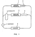
- Fig. 1 is a system diagram of a dual air conditioner to which the expansion valve according to the invention is applied.
- the automotive dual air conditioner includes a compressor 1, a condenser 2, an orifice tube 3, a front-side evaporator 4, and an accumulator 5, which form a refrigeration cycle for a front-side air conditioner.
- a rear side temperature-type expansion valve 6 and a rear-side evaporator 7 are connected in parallel with a circuit of the orifice tube 3, the front-side evaporator 4, and the accumulator 5. These components form part of a refrigeration cycle for a rear-side air conditioner.
- Refrigerant compressed by the compressor 1 is condensed by the condenser 2. Part of the liquid refrigerant formed by the condensation is guided into the orifice tube 3, and the remainder of the liquid refrigerant is guided to the expansion valve 6.
- the refrigerant guided into the orifice tube 3 is subjected to throttle expansion and changes into low-temperature and low-pressure refrigerant which is then caused to exchange heat with front-side cabin air in the front-side evaporator 4.
- Refrigerant evaporated by heat exchange in the front-side evaporator 4 is caused to undergo gas/liquid separation by the accumulator 5 and gaseous refrigerant obtained by the separation is returned to the compressor 1.
- the refrigerant guided into the rear side expansion valve 6 is subjected to throttling expansion according to the temperature and pressure of the refrigerant delivered from the rear-side evaporator 7 and changes into low-temperature and low-pressure refrigerant, which is then guided into the rear-side evaporator 7 to exchange heat with rear-side cabin air.
- the refrigerant is completely evaporated by the heat exchanged and then returns to the compressor 1.
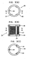
- the block-type expansion valve 6 [Fig. 2, Fig. 3 (A), Fig. 3 (B), Fig. 3 (C)] according to the present invention, which is used as the rear-side air conditioner expansion device, will be described in detail.
- a refrigerant pipe-connecting hole 12 is formed through a side portion of a body 11 of the expansion valve 6. Hole 12 is connected to a refrigerant pipe through which high-temperature and high-pressure refrigerant is supplied from the condenser 2.
- a refrigerant pipe-connecting hole 13 of body 11 is connected to a refrigerant pipe for supplying low-temperature and low-pressure refrigerant obtained by adiabatically expanding the high-temperature and high-pressure refrigerant by the expansion valve 6 to the rear-side evaporator 7.
- a refrigerant pipe-connecting hole 14 of the body 11 is connected to a refrigerant pipe extending from an outlet port of the evaporator, and a refrigerant pipe-connecting hole 15 of the body 11 is connected to a refrigerant pipe leading to the compressor 1.
- Arrows in Fig. 2 indicate respective flows of refrigerant.
- a valve seat 16 is integrally formed in the body 11.
- a ball valve element 17 is arranged at the upstream side of the valve seat 16 .
- a compression coil spring 18 is arranged for urging the valve element 17 to the valve seat 16.
- the compression coil spring 18 is supported by an adjustment screw 19 screwed into a threaded hole formed as a part of a stepped bore in a lower end of the body 11 for adjusting a pre-set value of a pressure at which the valve element 17 starts to open.
- the screwing depth is variable to change the load of the compression coil spring 18.
- a strainer 20 having a hollow cylindrical shape is arranged in the fluid passage part 12a also accommodating the valve element 17 and the compression coil spring 18, a strainer 20 having a hollow cylindrical shape is arranged.
- the strainer 20 surrounds both the valve element 17 and the compression coil spring 18.
- a cylindrical cavity 12c is formed with an inner diameter larger than the spring diameter.
- the strainer 20 comprises a hollow cylindrical net 21, annular frames 22, 23 for reinforcing both open cylinder ends of the net 21, and longitudinal frames 24 connecting the annular frames 22, 23, e.g. at three separated locations.
- the net 21 is embedded at least into the frame 24, preferably also into the annular frames 22, 23.
- the frames 22, 23, 24 are integrally formed with each other by resin moulding.
- Each annular frame 22, 23 is formed such that it has an outer diameter approximately equal to the inner diameter of the fluid passage part 12a, or the cavity 12c, respectively, where the strainer 20 is mounted.
- the frames 22, 23 are in contact with the inner wall of the body 11, or the inner cavity wall, respectively, when the strainer 20 is inserted in the cavity.
- the strainer 20 easily can be inserted into the cavity 12, before the spring 18 and the adjustment screw 19 are inserted.
- the net 21 has an outer diameter smaller than the inner diameter of the cavity 12c in the fluid passage part 12a or the frames 22, 23, 24, respectively, so as to maintain a radial gap between the net 21 and the inner wall of the cavity 12c.
- the refrigerant coming from the refrigerant pipe-connecting hole 12 flows through the net 21 into the space accommodating the valve element 17, and finds access to the net 21 along practically the whole periphery of the net 21.
- the strainer 20 is secured in place either by a press-fit in the cavity 12c and/or even by the adjustment screw 19.
- the strainer 20 may be elastic in axial direction.
- the expansion valve 6 further has a power element P arranged on an upper end of the body 11.
- the power element P comprises an upper housing 25, a lower housing 26, a diaphragm 27 dividing a space enclosed by the housings 25, 26, and a disc 28 at an underside of the diaphragm 27.
- a shaft 29 below the disc 28 transmits displacements of the diaphragm 27 to the valve element 17.
- the shaft 29 has an upper portion held by a holder 30 which crosses a fluid passage 14a, 15a extending in the body 11 between the holes 14, 15.
- the holder 30 receives a compression coil spring 31 for laterally loading an upper end of the shaft 29, such that the compression coil spring 31 controls longitudinal vibration of the shaft 29 which might occur in response to pressure fluctuations of the refrigerant.
- a bleed hole 32 bypassing the valve 17, 16, is formed in the body 11.
- the bleed hole 32 permits a very small amount of refrigerant flow, even when the valve 17, 16 is fully closed, to always supply lubricating oil contained in the refrigerant to the compressor 1.
- the power element P senses the pressure and temperature of the refrigerant returned from the rear-side evaporator 7 into the refrigerant pipe-connecting hole 14.
- the power element pushes the valve element 17 in the valve-opening direction.
- the power element allows the valve element 17 to move in the valve-closing direction, whereby the valve travel is controlled.
- the refrigerant supplied from the condenser 2 enters the refrigerant pipe-connecting hole 12, and flows through the net 21 of the strainer 20 into the space accommodating the valve element 17. Foreign matter contained in the refrigerant is removed.
- the cleaned refrigerant is subjected to throttling expansion in the valve 17, 16, the valve travel of which is controlled as described above, thereby changing into low-temperature and low-pressure refrigerant.
- the refrigerant then is discharged from the refrigerant pipe-connecting hole 13, and supplied to the rear-side evaporator 7, where the refrigerant is caused to exchange heat with rear-side cabin air, followed by returning to the refrigerant pipe-connecting hole 14 of the expansion valve 6.
Landscapes
- Physics & Mathematics (AREA)
- Engineering & Computer Science (AREA)
- Fluid Mechanics (AREA)
- Mechanical Engineering (AREA)
- Thermal Sciences (AREA)
- General Engineering & Computer Science (AREA)
- Temperature-Responsive Valves (AREA)
- Air-Conditioning For Vehicles (AREA)
- Details Of Valves (AREA)
Claims (9)
- Expansionsventil (6) eines Blocktyps, mit einem Leistungselement (P) zum Abgreifen einer Temperatur und des Drucks eines Kältemittels, das von einem Verdampfer geliefert wird, und mit einem Ventilbereich, der in einem blockförmigen Körper (11) des Expansionsventils ein Ventilelement (17) enthält, dadurch gekennzeichnet, dass in einer Fluidpassage (12a, 13a), in welcher das Ventilelement (17) angeordnet ist, ein hohles zylindrisches Sieb (20) montiert ist, derart, dass das Sieb (20) das Ventilelement (17) an der Stromaufseite direkt umgibt, und dass das Sieb (20) ein hohles zylindrisches Netz (21) aufweist, dessen beide offenen Enden durch ringförmige Rahmen (22, 23) verstärkt sind.
- Expansionsventil gemäß Anspruch 1, dadurch gekennzeichnet, dass die ringförmigen Rahmen (22, 23) mit längs verlaufenden Rahmen (24) integral ausgebildet sind, um das Netz (21) in einem Zustand zu halten, in welchem es darin eingebettet ist.
- Expansionsventil gemäß Anspruch 1, dadurch gekennzeichnet, dass die ringförmigen Rahmen (22, 23) in Kontakt mit dem die Fluidpassage (12a, 13a) definierenden Körper angeordnet sind, wobei das Ventilelement in der Fluidpassage so angeordnet ist, dass das Netz (21) in einem Passageteil (12a) angeordnet ist, welcher mit einer Kältemittelrohr-Anschlussöffnung (12) kommuniziert, durch welche unter hohem Druck stehendes Kältemittel eingeführt wird.
- Expansionsventil gemäß den vorhergehenden Ansprüchen, dadurch gekennzeichnet, dass das Sieb (20) in einem Passageteil (12a) des Körpers (11) montiert ist, welcher Passageteil (12) sich von einer Hochdruck-Einlassanschlussöffnung (12) zu einem Ventilsitz (16) erstreckt.
- Expansionsventil gemäß zumindest einem der Ansprüche 1 bis 4, dadurch gekennzeichnet, dass in dem Körper (11) an einem Körperendbereich entfemt von dem Leistungselement (P) eine abgestufte Bohrung ausgebildet ist, welche abgestufte Bohrung den Passageteil (12a) durchquert und sich zu dem Ventilsitz (16) erstreckt, und dass die abgestufte Bohrung eine Aufnahmeöffnung für eine mit einem Gewinde versehene Einstellschraube und einen Hohlraum (12c) zum Aufnehmen eines zylindrischen Siebes definiert mit einem kleinen inneren Durchmesser als dem inneren Durchmesser der mit Gewinde versehenen Öffnung zum Aufnahmen der Einstellschraube.
- Expansionsventil gemäß zumindest Anspruch 5, dadurch gekennzeichnet, dass das Sieb (20) in dem Hohlraum (12c) durch eine Presspassung seiner Rahmen (22, 23, 24) montiert ist.
- Expansionsventil gemäß Anspruch 6, dadurch gekennzeichnet, dass die Rahmen (22, 23, 24) von dem darin eingebetteten Netz (21) so nach außen vorstehen, dass zwischen dem Netz (21) und der inneren Hohlraumwand ein Umfangsspalt gebildet wird, der mit dem Passageteil (12a) kommuniziert.
- Expansionsventil gemäß Anspruch 5, dadurch gekennzeichnet, dass das Sieb (20) eine Schraubendruckfeder (18) enthält, die zwischen einer Federbelastungs-Einstellschraube (19) und dem Ventilelement (17) im Inneren der abgestuften Bohrung montiert ist.
- Expansionsventil gemäß Anspruch 1, dadurch gekennzeichnet, dass das Sieb (20) in axialer Richtung elastisch ist, und dass das Sieb (20) an Ort und Stelle in dem Hohlraum (12c) durch axialen Kontakt der Einstellschraube (19) festgelegt ist.
Applications Claiming Priority (2)
| Application Number | Priority Date | Filing Date | Title |
|---|---|---|---|
| JP2001332094 | 2001-10-30 | ||
| JP2001332094A JP2003130499A (ja) | 2001-10-30 | 2001-10-30 | 膨張弁 |
Publications (3)
| Publication Number | Publication Date |
|---|---|
| EP1308660A2 EP1308660A2 (de) | 2003-05-07 |
| EP1308660A3 EP1308660A3 (de) | 2003-10-01 |
| EP1308660B1 true EP1308660B1 (de) | 2007-03-21 |
Family
ID=19147564
Family Applications (1)
| Application Number | Title | Priority Date | Filing Date |
|---|---|---|---|
| EP02024460A Expired - Lifetime EP1308660B1 (de) | 2001-10-30 | 2002-10-29 | Entspannungsventil |
Country Status (5)
| Country | Link |
|---|---|
| US (1) | US6712281B2 (de) |
| EP (1) | EP1308660B1 (de) |
| JP (1) | JP2003130499A (de) |
| KR (1) | KR20030035992A (de) |
| DE (1) | DE60218957T2 (de) |
Families Citing this family (12)
| Publication number | Priority date | Publication date | Assignee | Title |
|---|---|---|---|---|
| JP2005226940A (ja) * | 2004-02-13 | 2005-08-25 | Fuji Koki Corp | 膨張弁 |
| DE102005050086A1 (de) * | 2004-11-08 | 2006-05-11 | Otto Egelhof Gmbh & Co. Kg | Expansionsventil, insbesondere für eine Kältemittelanlage |
| EP1666817A3 (de) * | 2004-12-01 | 2007-01-17 | Fujikoki Corporation | Druckregelventil |
| KR20060081922A (ko) * | 2005-01-11 | 2006-07-14 | 삼성전자주식회사 | 냉장고 |
| JP2006336927A (ja) * | 2005-06-01 | 2006-12-14 | Tgk Co Ltd | 冷凍サイクル |
| ES2743610T3 (es) * | 2005-12-21 | 2020-02-20 | Sulzer Management Ag | Procedimiento de desgasificación estática de un líquido que contiene polímeros |
| JP2007303746A (ja) * | 2006-05-11 | 2007-11-22 | Denso Corp | 冷凍サイクルおよび冷凍サイクル用部品組立体 |
| KR100854780B1 (ko) * | 2007-02-14 | 2008-08-27 | 주식회사 만도 | 필터 및 이를 포함하는 전자 제어 동력 보조 조향장치의압력 제어 밸브 |
| US8047449B2 (en) * | 2009-01-28 | 2011-11-01 | Automotive Components Holdings Llc | Automotive thermostatic expansion valve with reduced hiss |
| CN102141329B (zh) * | 2011-02-28 | 2013-06-26 | 浙江三花汽车零部件有限公司 | 一种汽车空调系统及其贮液器 |
| JP5891968B2 (ja) * | 2012-06-22 | 2016-03-23 | 株式会社デンソー | 減圧装置 |
| JP6142181B2 (ja) * | 2013-03-12 | 2017-06-07 | 株式会社テージーケー | 膨張弁および防振ばね |
Family Cites Families (17)
| Publication number | Priority date | Publication date | Assignee | Title |
|---|---|---|---|---|
| US1501858A (en) * | 1919-11-01 | 1924-07-15 | Delco Light Co | Expansion valve for refrigerating machines and the like |
| US1660842A (en) * | 1925-11-09 | 1928-02-28 | Peerless Ice Machine Company | Expansion valve |
| US2484156A (en) * | 1944-04-14 | 1949-10-11 | Alco Valve Co | Valve with dual control |
| US2508010A (en) * | 1945-06-09 | 1950-05-16 | Alco Valve Co | Thermal limit valve |
| US4015776A (en) * | 1976-01-23 | 1977-04-05 | The Singer Company | Thermostatic expansion valve |
| US4095742A (en) * | 1976-08-26 | 1978-06-20 | Virginia Chemicals Inc. | Balanced single port thermostatic expansion valve |
| US4130622A (en) * | 1977-02-22 | 1978-12-19 | Abbott Laboratories | Method of making self-supporting tubular filter |
| JP3165819B2 (ja) | 1991-07-22 | 2001-05-14 | アイシン・エィ・ダブリュ株式会社 | 自動変速機の油圧制御系における油ストレーナ |
| US5232015A (en) * | 1991-10-24 | 1993-08-03 | Sporlan Valve Company | Expansion valve with inlet strainer |
| US5238219A (en) * | 1992-03-13 | 1993-08-24 | Sporlan Valve Company | Thermostatic expansion valve |
| US5364066A (en) * | 1993-07-15 | 1994-11-15 | Sporlan Valve Company | Dual port valve with stepper motor actuator |
| DE19654340A1 (de) * | 1996-12-24 | 1998-08-06 | Huels Chemische Werke Ag | Verfahren zur Herstellung von höheren Oxo-Alkoholen |
| JPH11325655A (ja) * | 1998-05-14 | 1999-11-26 | Matsushita Seiko Co Ltd | 消音器および空気調和機 |
| JP2000241048A (ja) | 1999-02-24 | 2000-09-08 | Saginomiya Seisakusho Inc | 感温膨張弁 |
| JP3820066B2 (ja) | 1999-10-15 | 2006-09-13 | 株式会社テージーケー | 冷凍装置用膨張弁 |
| DE60027846T2 (de) | 1999-12-06 | 2006-11-30 | Siemens Vdo Automotive Corp., Auburn Hills | Filter für Druckregelungssystem |
| JP3515048B2 (ja) * | 2000-06-21 | 2004-04-05 | 株式会社テージーケー | 過冷却度制御式膨張弁 |
-
2001
- 2001-10-30 JP JP2001332094A patent/JP2003130499A/ja active Pending
-
2002
- 2002-10-24 US US10/279,503 patent/US6712281B2/en not_active Expired - Fee Related
- 2002-10-29 EP EP02024460A patent/EP1308660B1/de not_active Expired - Lifetime
- 2002-10-29 KR KR1020020066062A patent/KR20030035992A/ko not_active Withdrawn
- 2002-10-29 DE DE60218957T patent/DE60218957T2/de not_active Expired - Fee Related
Non-Patent Citations (1)
| Title |
|---|
| None * |
Also Published As
| Publication number | Publication date |
|---|---|
| EP1308660A2 (de) | 2003-05-07 |
| DE60218957D1 (de) | 2007-05-03 |
| US6712281B2 (en) | 2004-03-30 |
| EP1308660A3 (de) | 2003-10-01 |
| DE60218957T2 (de) | 2007-06-28 |
| US20030079493A1 (en) | 2003-05-01 |
| JP2003130499A (ja) | 2003-05-08 |
| KR20030035992A (ko) | 2003-05-09 |
Similar Documents
| Publication | Publication Date | Title |
|---|---|---|
| US4756166A (en) | Integral receiver/dehydrator and expansion valve for air conditioning systems | |
| EP1308660B1 (de) | Entspannungsventil | |
| CA2011741C (en) | Transport refrigeration system having means for enhancing the capacity of a heating cycle | |
| US5642858A (en) | Thermal expansion valve | |
| US20040172958A1 (en) | Vapor-compression-type refrigerating machine | |
| US6612503B2 (en) | Expansion valve | |
| US20070209387A1 (en) | Expansion valve | |
| KR100378536B1 (ko) | 팽창밸브 부착 리시버 탱크 | |
| US6321995B1 (en) | Thermostatic expansion valve | |
| US5943871A (en) | Thermal expansion valve | |
| US6868684B2 (en) | Block valve with integral refrigerant lines | |
| JP2005098597A (ja) | 冷凍サイクル | |
| US6328061B1 (en) | Variable flow area refrigerant expansion device | |
| US4632305A (en) | Expansion valve | |
| EP1209426B1 (de) | Entspannungsventil | |
| JP3996429B2 (ja) | 膨張弁 | |
| JP3920059B2 (ja) | 膨張弁 | |
| GB2366354A (en) | Noise reduction in expansion valves for a refrigerant cycle | |
| EP0255035B1 (de) | Kältekreislauf | |
| JP2001183032A (ja) | 温度式膨張弁 | |
| JPH05196324A (ja) | 冷凍サイクル用膨張弁 | |
| JP3442949B2 (ja) | 可変容量圧縮機を用いた冷凍サイクル | |
| JP2003130501A (ja) | 膨張弁 | |
| JP2003113950A (ja) | 四方向切換弁 | |
| KR100566834B1 (ko) | 차량용 냉각싸이클의 오일바이패스회로 |
Legal Events
| Date | Code | Title | Description |
|---|---|---|---|
| PUAI | Public reference made under article 153(3) epc to a published international application that has entered the european phase |
Free format text: ORIGINAL CODE: 0009012 |
|
| AK | Designated contracting states |
Designated state(s): AT BE BG CH CY CZ DE DK EE ES FI FR GB GR IE IT LI LU MC NL PT SE SK TR |
|
| AX | Request for extension of the european patent |
Extension state: AL LT LV MK RO SI |
|
| PUAL | Search report despatched |
Free format text: ORIGINAL CODE: 0009013 |
|
| AK | Designated contracting states |
Kind code of ref document: A3 Designated state(s): AT BE BG CH CY CZ DE DK EE ES FI FR GB GR IE IT LI LU MC NL PT SE SK TR |
|
| AX | Request for extension of the european patent |
Extension state: AL LT LV MK RO SI |
|
| 17P | Request for examination filed |
Effective date: 20030909 |
|
| AKX | Designation fees paid |
Designated state(s): DE ES FR GB IT |
|
| 17Q | First examination report despatched |
Effective date: 20060807 |
|
| GRAP | Despatch of communication of intention to grant a patent |
Free format text: ORIGINAL CODE: EPIDOSNIGR1 |
|
| GRAS | Grant fee paid |
Free format text: ORIGINAL CODE: EPIDOSNIGR3 |
|
| GRAA | (expected) grant |
Free format text: ORIGINAL CODE: 0009210 |
|
| AK | Designated contracting states |
Kind code of ref document: B1 Designated state(s): DE ES FR GB IT |
|
| REG | Reference to a national code |
Ref country code: GB Ref legal event code: FG4D |
|
| REF | Corresponds to: |
Ref document number: 60218957 Country of ref document: DE Date of ref document: 20070503 Kind code of ref document: P |
|
| PG25 | Lapsed in a contracting state [announced via postgrant information from national office to epo] |
Ref country code: ES Free format text: LAPSE BECAUSE OF FAILURE TO SUBMIT A TRANSLATION OF THE DESCRIPTION OR TO PAY THE FEE WITHIN THE PRESCRIBED TIME-LIMIT Effective date: 20070702 |
|
| PLBE | No opposition filed within time limit |
Free format text: ORIGINAL CODE: 0009261 |
|
| STAA | Information on the status of an ep patent application or granted ep patent |
Free format text: STATUS: NO OPPOSITION FILED WITHIN TIME LIMIT |
|
| 26N | No opposition filed |
Effective date: 20071227 |
|
| PG25 | Lapsed in a contracting state [announced via postgrant information from national office to epo] |
Ref country code: IT Free format text: LAPSE BECAUSE OF FAILURE TO SUBMIT A TRANSLATION OF THE DESCRIPTION OR TO PAY THE FEE WITHIN THE PRESCRIBED TIME-LIMIT Effective date: 20070321 |
|
| GBPC | Gb: european patent ceased through non-payment of renewal fee |
Effective date: 20071029 |
|
| PG25 | Lapsed in a contracting state [announced via postgrant information from national office to epo] |
Ref country code: GB Free format text: LAPSE BECAUSE OF NON-PAYMENT OF DUE FEES Effective date: 20071029 |
|
| PGFP | Annual fee paid to national office [announced via postgrant information from national office to epo] |
Ref country code: DE Payment date: 20081127 Year of fee payment: 7 |
|
| PGFP | Annual fee paid to national office [announced via postgrant information from national office to epo] |
Ref country code: FR Payment date: 20081024 Year of fee payment: 7 |
|
| REG | Reference to a national code |
Ref country code: FR Ref legal event code: ST Effective date: 20100630 |
|
| PG25 | Lapsed in a contracting state [announced via postgrant information from national office to epo] |
Ref country code: FR Free format text: LAPSE BECAUSE OF NON-PAYMENT OF DUE FEES Effective date: 20091102 Ref country code: DE Free format text: LAPSE BECAUSE OF NON-PAYMENT OF DUE FEES Effective date: 20100501 |