EP1308632B1 - Vorrichtung zur elastischen Anordnung eines Elektromotors - Google Patents
Vorrichtung zur elastischen Anordnung eines Elektromotors Download PDFInfo
- Publication number
- EP1308632B1 EP1308632B1 EP02024422A EP02024422A EP1308632B1 EP 1308632 B1 EP1308632 B1 EP 1308632B1 EP 02024422 A EP02024422 A EP 02024422A EP 02024422 A EP02024422 A EP 02024422A EP 1308632 B1 EP1308632 B1 EP 1308632B1
- Authority
- EP
- European Patent Office
- Prior art keywords
- shell
- elastic
- shaped element
- electric motor
- shaped
- Prior art date
- Legal status (The legal status is an assumption and is not a legal conclusion. Google has not performed a legal analysis and makes no representation as to the accuracy of the status listed.)
- Expired - Lifetime
Links
- 239000000463 material Substances 0.000 claims description 7
- 229920001296 polysiloxane Polymers 0.000 claims description 5
- 239000013013 elastic material Substances 0.000 claims description 4
- 230000000295 complement effect Effects 0.000 claims 1
- 238000006073 displacement reaction Methods 0.000 claims 1
- 238000002955 isolation Methods 0.000 abstract description 12
- 238000005192 partition Methods 0.000 description 5
- 238000013016 damping Methods 0.000 description 2
- 238000009434 installation Methods 0.000 description 2
- 238000009413 insulation Methods 0.000 description 2
- 238000010276 construction Methods 0.000 description 1
- 238000002347 injection Methods 0.000 description 1
- 239000007924 injection Substances 0.000 description 1
- 230000007774 longterm Effects 0.000 description 1
- 238000000034 method Methods 0.000 description 1
- 239000000725 suspension Substances 0.000 description 1
Images


Classifications
-
- H—ELECTRICITY
- H02—GENERATION; CONVERSION OR DISTRIBUTION OF ELECTRIC POWER
- H02K—DYNAMO-ELECTRIC MACHINES
- H02K5/00—Casings; Enclosures; Supports
- H02K5/24—Casings; Enclosures; Supports specially adapted for suppression or reduction of noise or vibrations
-
- F—MECHANICAL ENGINEERING; LIGHTING; HEATING; WEAPONS; BLASTING
- F04—POSITIVE - DISPLACEMENT MACHINES FOR LIQUIDS; PUMPS FOR LIQUIDS OR ELASTIC FLUIDS
- F04D—NON-POSITIVE-DISPLACEMENT PUMPS
- F04D29/00—Details, component parts, or accessories
- F04D29/66—Combating cavitation, whirls, noise, vibration or the like; Balancing
- F04D29/661—Combating cavitation, whirls, noise, vibration or the like; Balancing especially adapted for elastic fluid pumps
- F04D29/668—Combating cavitation, whirls, noise, vibration or the like; Balancing especially adapted for elastic fluid pumps damping or preventing mechanical vibrations
-
- F—MECHANICAL ENGINEERING; LIGHTING; HEATING; WEAPONS; BLASTING
- F16—ENGINEERING ELEMENTS AND UNITS; GENERAL MEASURES FOR PRODUCING AND MAINTAINING EFFECTIVE FUNCTIONING OF MACHINES OR INSTALLATIONS; THERMAL INSULATION IN GENERAL
- F16F—SPRINGS; SHOCK-ABSORBERS; MEANS FOR DAMPING VIBRATION
- F16F15/00—Suppression of vibrations in systems; Means or arrangements for avoiding or reducing out-of-balance forces, e.g. due to motion
- F16F15/02—Suppression of vibrations of non-rotating, e.g. reciprocating systems; Suppression of vibrations of rotating systems by use of members not moving with the rotating systems
- F16F15/04—Suppression of vibrations of non-rotating, e.g. reciprocating systems; Suppression of vibrations of rotating systems by use of members not moving with the rotating systems using elastic means
- F16F15/08—Suppression of vibrations of non-rotating, e.g. reciprocating systems; Suppression of vibrations of rotating systems by use of members not moving with the rotating systems using elastic means with rubber springs ; with springs made of rubber and metal
Definitions
- the invention relates to a device for the elastic arrangement of a Electric motor in a receptacle, being between an electric motor and a receptacle is arranged at least one elastic insulating element.
- Such electric motors can, for example, in a blower in a Vehicle are used, whereby the problem occurs that the Positioning of the fan, in particular the fan wheel of the fan Blower must be long-term stable relative to its housing, so that the Fan does not touch on its housing. This could Damage and / or disturbing noises are caused.
- the electric motor supporting the fan must be in the entire operating range of the vehicle so softly suspended, that vibrations in the region of the electric motor, for example, not by Structure-borne noise can be transmitted to other components of the vehicle and could be perceived as disturbing to the occupants of the vehicle.
- the object of the invention is to provide an arrangement of the type mentioned above create, which is improved over the prior art. Furthermore is it is an object of the invention in such a device a Vibration isolation of the engine at the same time improved To create positioning.
- At least one insulating element in particular for Vibration isolation of a first cup-shaped element, a second cup-shaped element and an elastic element.
- the elastic element is advantageously substantially of the surrounded by cup-shaped elements. It is particularly advantageous when the first cup-shaped element and / or the second cup-shaped Element has at least one projection in at least one Recess of the second cup-shaped element or the first Elements intervenes.
- a relative movement of the one cupped part relative to the other cup-shaped part be and / or in another embodiment in their amplitude be limited.
- this can also be achieved if the first and / or second cup-shaped element a collar or Finger having the second or first cup-shaped element at least partially encompasses.
- first cup-shaped element and / or the second cup-shaped element at least one stop means having, with at least one counter-stop means of the second and / or first cup-shaped element cooperates, by means of which a relative movement of the one cup-shaped element relative to the is limited to other bowl-shaped element.
- This limitation of Relative movement of a bowl-shaped element relative to the other bowl-shaped element is appropriate, because thereby the Displaceability of the electric motor and thus also the fan in the Operation is limited. Due to the soft suspension of the engine by the elastic element is a vibration isolation and the stop means cause a limitation of the maximum deflection or Relative movement.
- this could, for example, a Balancing process of the fan and / or the fan omitted, since by the advantageous decoupling of the electric motor by at least one Isolation element does not vibrate on other components of the vehicle would be transmitted, which at a certain existing imbalance would arise.
- the slings are still appropriate manner provided, so larger Relativverschiebungon in operation on a allowed measure be limited.
- the elastic element a has cuboid shape.
- the outer shape may also be realized in a different way, such as for example in the form of a cylinder, a barrel or as polygonal element. It may be useful if the elastic Element has at least one continuous channel that does not communicate with the elastic material is filled. It may also be appropriate if the elastic element has at least individual recesses and / or the elastic element has a plurality of recesses, the by partitions of the elastic material against each other are delimited.
- the elastic element consists of a Material exists and thus is formed substantially pure sort. This is advantageous for the procurement, but also for the later Disposal environmentally friendly. It is particularly advantageous if the elastic element is made of silicone. This has the advantage that the Material in the temperature range of application in a motor vehicle no strong fluctuations in its elastic properties and / or in terms of dimensional stability.
- the elastic element of at least two materials exists, so that the resonance behavior of the device tuned better can be. It is expedient if one of the materials silicone is.
- FIG. 1 shows an electric motor 10 which is mounted on its shaft 11
- an impeller 12 carries, with its hub 13 with the Wave 11 is connected.
- a motor adapter 22 for receiving the electric motor intended.
- the motor adapter can be designed as an annular or cup-shaped Be formed element in which the electric motor 10 is inserted, wherein the motor adapter holds the housing 21 of the electric motor.
- Variants of the motor adapter can this depending on Construction space situation also be configured differently, such as multi-part, with the individual parts of the motor adapter then with the Electric motor, in particular as can be connected to the housing 21.
- the motor adapter as a whole or in parts is formed integrally with the housing of the electric motor and thus forms an integral part of the housing.
- the motor adapter can the electric motor to a motor holder 30 of a housing or a be fastened to another part of a motor vehicle.
- a motor holder 30 Between the Motor adapter 22 and the motor holder 30 is at least one insulating element 40 provided.
- This isolation element 40 ensures at least one slight displaceability of the electric motor relative to the motor holder 30 and allows at the same time a damping and / or isolation of Vibrations emanating from the electric motor, so this largely isolated, subdued or suppressed and not or only slightly by means of structure-borne noise on other components of the vehicle be transmitted.
- the at least one insulation element 40 advantageously consists of two cup-shaped elements 41 and 42, between which an elastic Element 43 is arranged.
- the first cup-shaped element 41 is thereby connectable to the electric motor or with the motor adapter 22 or formed integrally with this.
- the second cup-shaped element 42 is connected to the motor holder 30 or advantageously integrally with this educated.
- Elastic element may be the electric motor relative to the motor mount slightly in the radial and / or axial direction and / or in Circumferential direction or in one direction, resulting from all three Coordinate directions composed, as in a tilting movement be movable.
- the elastic element preferably has one Structure on which a corresponding elastic connection of the Electric motor in the respective directions (radial or axial or in Circumferential direction). So can an anisotropic elastic Behavior of the elastic element to be controlled.
- the elastic behavior of the elastic Elementes is substantially independent of temperature or only a very low temperature dependence in the usual temperature range of Owns vehicle. It is expedient if the element of silicone is made.
- FIG. 2 shows in a partial view a schematic arrangement of a Isolation element 40 in the arrangement between the electric motor 10 and Motor holder 30, wherein the motor holder may be a plastic injection molded part, the recesses or receptacles for receiving the cup-shaped Has elements 42.
- the electric motor 10 with its housing can a Motor adapter which receives the cup-shaped elements 41 or the electric motor can itself these bowl-shaped elements Take pictures. Also, the cup-shaped elements could with Motor holder, motor adapter or motor housing to be integrally formed.
- the one shell-shaped element 41,42 has at least one projection or projections 50,52, in at least a recess or more recesses 51,53 of the other part 42.41 intervene.
- the spatial extent of the Recesses is greater than the spatial extent of the projections, This can be a bowl-shaped element under the action of the interposed elastic element against a restoring force be shifted relative to the other bowl-shaped element.
- a Limiting the shiftability is via slings and Gegenanschlagstoffsch 54,55,56,57,58,59, so that in each case the slings 54,55 and 59 cooperate with Schmidtmitleln 56.57 and 58 can.
- the elastic element For receiving the elastic element has at least one cup-shaped element has a receptacle 60 which has a circumferential Edge 61 or other means for fixing the position of the elastic means having. These other means may also be projections or the like. It is expedient if the spatial extent of the receptacle 60 is equal to or smaller than the spatial extent of the elastic Element 43 in the plane of the receptacle 60 is. This will do that elastic element backlash-free and possibly under pretension added. It may in other embodiments of the invention also find other forms of use.
- the elastic means 43 is formed substantially cuboid and has recesses 70 or continuous channels through Partitions 71 are separated from each other. This can make the elasticity the elastic element can be controlled selectively, wherein the elasticity in The different coordinate directions specifically different can be chosen.
- FIG. 4 shows a further exemplary embodiment of an arrangement of FIG cup-shaped elements, wherein the cup-shaped element 80 the cup-shaped element 81 partially surrounds and through the encompassing areas are stop means 82 and counter stop means 83 form a relative movement of the two parts to each other limit. Also, with regard to the vertical movement of the parts 80 and 81 stop means 84 and counter-stop means 85 is provided which a limit relative movement of the two parts.
- FIG. 5 shows a section through an elastic element 90, wherein this substantially cuboidal element recesses 93rd are provided by the partitions 91, 94 and 92 of each other are separated. It may be useful if one or the other Partition 92 or 94 is located in the focal plane of the blower, the is driven by the electric motor. It is particularly advantageous if this is true for the partition wall 92.
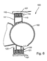
- FIG. 6 shows an embodiment of a device 100 for elastic arrangement of an electric motor in a receptacle or a Motor holder 101. It is between the electric motor and recording 101st at least one elastic insulation element 110 is arranged.
- the Isolation element 110 consists of at least a first cup-shaped element 111, a second cup-shaped element 112 and an elastic member 113.
- the first shell 111 connected to the motor adapter 102 and the second Shell is connected to the motor holder 101. Between these shells is an elastic element 113 is arranged.
- the shells 112 or 111 have securing means, so that after a Assembly of the first shell with the second shell this means of Lashing are held such that the parts during transport not fall apart.
- These are advantageously at least one of Parts provided arms 121 which are provided with projections 122 which grab the other shell-like element and thus prevent the one Part separated from the other part without great force can.
- the projections point in the direction of the other shell-like component.
- the recording of the cup-like Elements designed such that in the event that the shell-like parts to the lugs of the captive are held, the elastic element does not fall out of the picture.
- Particularly advantageous is a device for the elastic arrangement of a Electric motor in a receptacle according to the present invention, in which the blower or another part driven by an electric motor is used in standing installation or horizontal installation.
Landscapes
- Engineering & Computer Science (AREA)
- General Engineering & Computer Science (AREA)
- Mechanical Engineering (AREA)
- Physics & Mathematics (AREA)
- Chemical & Material Sciences (AREA)
- Combustion & Propulsion (AREA)
- Power Engineering (AREA)
- Acoustics & Sound (AREA)
- Aviation & Aerospace Engineering (AREA)
- Motor Or Generator Frames (AREA)
- Lock And Its Accessories (AREA)
- Vibration Prevention Devices (AREA)
- Springs (AREA)
Description
- Figur 1
- eine Vorrichtung zur elastischen Anordnung eines Elektromotors,
- Figur 2
- eine Anordnung von schalenförmigen Elementen,
- Figur 3
- eine Darstellung schalenförmiger Elemente,
- Figur 4
- eine Darstellung von schalenförmigen Elementen,
- Figur 5
- eine Darstellung eines elastischen Elementes im Schnitt und
- Figur 6
- eine Darstellung einer Anordnung eines elastischen Elements.
Claims (13)
- Vorrichtung zur eiastischen Anordnung eines Eiektromotors in einer Aufnahme, wobei zwischen Elektromotor und Aufnahme zumindest ein elastisches Isolationselement angeordnet ist, dadurch gekennzeichnet, daß das Isolationselement aus einem ersten schalenförmigen Element, einem zweiten schalenförmigen Element und einem elastischen Element besteht.
- Vorrichtung nach Anspruch 1, dadurch gekennzeichnet, daß das erste schalenförmige Element und/oder das zweite schalenförmige Element zumindest einen Vorsprung aufweist, der in zumindest eine Ausnehmung des zweiten schalenförmigen Elements bzw. des ersten Elements eingreift.
- Vorrichtung nach Anspruch 1, dadurch gekennzeichnet, daß das erste und/oder zweite schalenförmige Element einen Kragen aufweist, der das zweite bzw. erste schalenförmige Element zumindest teilweise umgreift.
- Vorrichtung nach Anspruch 2 oder 3, dadurch gekennzeichnet, daß das erste schalenförmige Element relativ zum zweiten schalenförmigen Element bewegbar ist.
- Vorrichtung nach Anspruch 4, dadurch gekennzeichnet, daß das erste schalenförmige Element und/oder das zweite schalenförmige Element Anschlagmittel aufweist, die mit Gegenanschlagmitteln des zweiten und/oder ersten schalenförmigen Elementes zusammenwirken, mittels welchen eine relative Bewegung des ersten schalenförmigen Elementes relativ zu dem zweiten schalenförmigen Elementes begrenzt wird.
- Vorrichtung nach Anspruch 1, dadurch gekennzeichnet, daß das elastische Element eine quaderförmige Gestalt aufweist.
- Vorrichtung nach Anspruch 6, dadurch gekennzeichnet, daß das elastische Element einen durchgängigen Kanal aufweist, der nicht mit dem elastischen Material ausgefüllt ist.
- Vorrichtung nach Anspruch 7, dadurch gekennzeichnet, daß das elastische Element zumindest einzelne Aussparungen aufweist.
- Vorrichtung nach Anspruch 8, dadurch gekennzeichnet, daß das elastische Element eine Mehrzahl von Aussparungen aufweist, die durch Trennwände aus dem elastischen Material gegeneinander abgegrenzt sind.
- Vorrichtung nach einem der vorhergehenden Ansprüche 1 und 6 bis 9, dadurch gekennzeichnet, daß das elastische Element aus einem Material besteht.
- Vorrichtung nach einem der vorhergehenden Ansprüche 1 und 6 bis 10, dadurch gekennzeichnet, daß das elastische Element aus Silikon besteht.
- Vorrichtung nach einem der Ansprüche 1 und 6 bis 9, dadurch gekennzeichnet, daß das elastische Element aus zumindest zwei Materialien besteht.
- Vorrichtung nach Anspruch 12, dadurch gekennzeichnet, daß eines der Materialien Silikon ist.
Applications Claiming Priority (2)
| Application Number | Priority Date | Filing Date | Title |
|---|---|---|---|
| DE10153908 | 2001-11-02 | ||
| DE10153908A DE10153908A1 (de) | 2001-11-02 | 2001-11-02 | Vorrichtung zur elastischen Anordnung eines Elektromoters |
Publications (2)
| Publication Number | Publication Date |
|---|---|
| EP1308632A1 EP1308632A1 (de) | 2003-05-07 |
| EP1308632B1 true EP1308632B1 (de) | 2004-10-20 |
Family
ID=7704426
Family Applications (1)
| Application Number | Title | Priority Date | Filing Date |
|---|---|---|---|
| EP02024422A Expired - Lifetime EP1308632B1 (de) | 2001-11-02 | 2002-10-28 | Vorrichtung zur elastischen Anordnung eines Elektromotors |
Country Status (4)
| Country | Link |
|---|---|
| EP (1) | EP1308632B1 (de) |
| AT (1) | ATE280330T1 (de) |
| DE (2) | DE10153908A1 (de) |
| ES (1) | ES2230439T3 (de) |
Families Citing this family (11)
| Publication number | Priority date | Publication date | Assignee | Title |
|---|---|---|---|---|
| EP1622240B1 (de) * | 2004-07-29 | 2015-12-23 | MAHLE Behr GmbH & Co. KG | Gehäuse zur Aufnahme eines Elektromotors |
| FR2926411B1 (fr) * | 2008-01-15 | 2015-05-22 | Valeo Systemes Thermiques | Dispositif de support de moteur pour systeme de ventilation, chauffage et/ou climatisation. |
| DE102011084237A1 (de) * | 2011-10-10 | 2013-04-11 | Behr Gmbh & Co. Kg | Schwingungsdämpfer, Dämpfungsvorrichtung und Lüfter |
| DE102011088583A1 (de) * | 2011-12-14 | 2013-06-20 | Behr Gmbh & Co. Kg | Entkopplungsvorrichtung |
| DE102014224917A1 (de) * | 2014-12-04 | 2016-06-09 | Mahle International Gmbh | Gebläse |
| DE102014224926A1 (de) | 2014-12-04 | 2016-06-09 | Mahle International Gmbh | Motorhaltevorrichtung |
| DE102014224910A1 (de) * | 2014-12-04 | 2016-06-09 | Mahle International Gmbh | Gebläse |
| DE102015208473A1 (de) * | 2015-05-07 | 2016-11-10 | Mahle International Gmbh | Gebläseeinrichtung |
| CN108150605A (zh) * | 2017-12-18 | 2018-06-12 | 北京大块科技有限公司 | 一种阻尼减震器及其制造方法 |
| DE102021116920A1 (de) * | 2021-06-30 | 2023-01-05 | Valeo Klimasysteme Gmbh | Gebläsemotorlagerung, insbesondere in einem Heizungs-, Lüftungs- und Klimagerät |
| DE102022203206A1 (de) | 2022-03-31 | 2023-10-05 | Vitesco Technologies GmbH | Elektrische Maschine und Fahrzeug mit mindestens einer derartigen elektrischen Maschine |
Family Cites Families (8)
| Publication number | Priority date | Publication date | Assignee | Title |
|---|---|---|---|---|
| DE1870497U (de) * | 1963-02-22 | 1963-04-18 | Himmelwerk A G | Schwingungsdaempfende aufhaengung eines elektromotors. |
| FR1521494A (fr) * | 1967-03-07 | 1968-04-19 | Peugeot | Ensemble formé d'un moteur ou autre dispositif supporté générateur de vibrationset de son dispositif de support amortisseur |
| US4161667A (en) * | 1977-11-16 | 1979-07-17 | A. O. Smith Corporation | Flexible mounting of electric motors |
| DE4329804A1 (de) * | 1993-09-03 | 1995-03-09 | Behr Gmbh & Co | Halterung für einen Elektromotor insbesondere für ein Gebläserad einer Heizungs- oder Klimaanlage |
| FR2732524B1 (fr) * | 1995-04-03 | 1997-05-09 | Valeo Thermique Habitacle | Dispositif de fixation elastique d'un moteur electrique a l'interieur d'un boitier, notamment pour vehicule automobile |
| FR2740625B1 (fr) * | 1995-10-31 | 1997-12-12 | Valeo Climatisation | Dispositif de fixation elastique d'un moteur electrique, notamment pour vehicule automobile |
| FR2752108B1 (fr) * | 1996-07-31 | 2004-01-23 | Valeo Climatisation | Dispositif perfectionne de fixation elastique d'un moteur electrique, notamment pour vehicule automobile |
| DE19652328C2 (de) * | 1996-12-16 | 2000-09-28 | Siemens Ag | Geräuschgedämmte Halterung eines Elektromotors und Verfahren zum Zusammenbau der Halterung |
-
2001
- 2001-11-02 DE DE10153908A patent/DE10153908A1/de not_active Withdrawn
-
2002
- 2002-10-28 AT AT02024422T patent/ATE280330T1/de not_active IP Right Cessation
- 2002-10-28 EP EP02024422A patent/EP1308632B1/de not_active Expired - Lifetime
- 2002-10-28 DE DE50201342T patent/DE50201342D1/de not_active Expired - Lifetime
- 2002-10-28 ES ES02024422T patent/ES2230439T3/es not_active Expired - Lifetime
Also Published As
| Publication number | Publication date |
|---|---|
| ES2230439T3 (es) | 2005-05-01 |
| DE10153908A1 (de) | 2003-05-15 |
| DE50201342D1 (de) | 2004-11-25 |
| EP1308632A1 (de) | 2003-05-07 |
| ATE280330T1 (de) | 2004-11-15 |
Similar Documents
| Publication | Publication Date | Title |
|---|---|---|
| EP1308632B1 (de) | Vorrichtung zur elastischen Anordnung eines Elektromotors | |
| EP1212824B1 (de) | Vorrichtung zur schwingungsisolierenden halterung eines elektromotors | |
| EP0642206B1 (de) | Halterung für einen Elektromotor, insbesondere für ein Gebläserad einer Heizungs- oder Klimaanlage | |
| DE102008010947C5 (de) | Bürstenloser Motor und Verfahren zur Herstellung desselben | |
| DE19706852A1 (de) | Haltevorrichtung für einen Elektromotor | |
| EP0986489B1 (de) | Entkopplungsvorrichtung für einen elektromotor | |
| DE69814417T2 (de) | Endkappe für einen ultra-lärmarmen elektrischen Motor | |
| DE4334202A1 (de) | Elektromotor mit einem zumindest annähernd rohrförmigen Gehäuseabschnitt | |
| DE29706216U1 (de) | Anordnung zur schwingungsisolierenden Aufhängung eines Elektromotors | |
| DE2935879A1 (de) | Elastischer, gedaempfter traeger | |
| DE69601007T2 (de) | Vorrichtung zur elastischen Befestigung eines Elektromotors in einem Gehäuse, insbesondere für Kraftfahrzeuge | |
| DE102014224926A1 (de) | Motorhaltevorrichtung | |
| DE19960328B4 (de) | Schwingungsaufnehmer mit einer Druckhülse | |
| EP3646436A1 (de) | Elektromotor | |
| DE102011013685A1 (de) | Schwingungsdämpfende Aufnahmevorrichtung | |
| DE19839640B4 (de) | Motor mit in einer Lageraufnahme mit Axialspieleinstellung für eine Rotorwelle fixierbarem Kalottenlager und Verfahren zur Axialspieleinstellung für eine Rotorwelle | |
| EP0636808A1 (de) | Halter zur schwingungsentkoppelten Befestigung von einem im wesentlichen plattenförmigen Maschinenelement | |
| DE19755805A1 (de) | Antriebseinheit | |
| DE102017004126A1 (de) | Drehschwingungsdämpfer | |
| EP1056185B1 (de) | Anordnung zur schwingungsisolierenden Halterung eines Elektromotors | |
| EP0718957B1 (de) | Pumpe für ein Hochdruckreinigungsgerät | |
| EP0715073B1 (de) | Einzelspulenzündsystem zum Anordnen im Zylinderkopf einer Brennkraftmaschine | |
| EP0926803B1 (de) | Anordnung zur schwingungsisolierenden Halterung eines Elektromotors | |
| EP1335479B1 (de) | Schwingungsisolierende Halterung eines Elektromotors | |
| DE19819237B4 (de) | Elastisch lagernde Steckkupplung |
Legal Events
| Date | Code | Title | Description |
|---|---|---|---|
| PUAI | Public reference made under article 153(3) epc to a published international application that has entered the european phase |
Free format text: ORIGINAL CODE: 0009012 |
|
| AK | Designated contracting states |
Designated state(s): AT BE BG CH CY CZ DE DK EE ES FI FR GB GR IE IT LI LU MC NL PT SE SK TR |
|
| AX | Request for extension of the european patent |
Extension state: AL LT LV MK RO SI |
|
| 17P | Request for examination filed |
Effective date: 20031022 |
|
| 17Q | First examination report despatched |
Effective date: 20031114 |
|
| AKX | Designation fees paid |
Designated state(s): AT BE BG CH CY CZ DE DK EE ES FI FR GB GR IE IT LI LU MC NL PT SE SK TR |
|
| GRAP | Despatch of communication of intention to grant a patent |
Free format text: ORIGINAL CODE: EPIDOSNIGR1 |
|
| RIN1 | Information on inventor provided before grant (corrected) |
Inventor name: GROEMME, CHRISTIAN, DIPL. ING. Inventor name: BITZER, MARKUS, DIPL. ING. |
|
| GRAS | Grant fee paid |
Free format text: ORIGINAL CODE: EPIDOSNIGR3 |
|
| GRAA | (expected) grant |
Free format text: ORIGINAL CODE: 0009210 |
|
| AK | Designated contracting states |
Kind code of ref document: B1 Designated state(s): AT BE BG CH CY CZ DE DK EE ES FI FR GB GR IE IT LI LU MC NL PT SE SK TR |
|
| PG25 | Lapsed in a contracting state [announced via postgrant information from national office to epo] |
Ref country code: SE Free format text: LAPSE BECAUSE OF FAILURE TO SUBMIT A TRANSLATION OF THE DESCRIPTION OR TO PAY THE FEE WITHIN THE PRESCRIBED TIME-LIMIT Effective date: 20041020 Ref country code: EE Free format text: LAPSE BECAUSE OF FAILURE TO SUBMIT A TRANSLATION OF THE DESCRIPTION OR TO PAY THE FEE WITHIN THE PRESCRIBED TIME-LIMIT Effective date: 20041020 Ref country code: TR Free format text: LAPSE BECAUSE OF FAILURE TO SUBMIT A TRANSLATION OF THE DESCRIPTION OR TO PAY THE FEE WITHIN THE PRESCRIBED TIME-LIMIT Effective date: 20041020 Ref country code: NL Free format text: LAPSE BECAUSE OF FAILURE TO SUBMIT A TRANSLATION OF THE DESCRIPTION OR TO PAY THE FEE WITHIN THE PRESCRIBED TIME-LIMIT Effective date: 20041020 Ref country code: IE Free format text: LAPSE BECAUSE OF FAILURE TO SUBMIT A TRANSLATION OF THE DESCRIPTION OR TO PAY THE FEE WITHIN THE PRESCRIBED TIME-LIMIT Effective date: 20041020 Ref country code: SK Free format text: LAPSE BECAUSE OF FAILURE TO SUBMIT A TRANSLATION OF THE DESCRIPTION OR TO PAY THE FEE WITHIN THE PRESCRIBED TIME-LIMIT Effective date: 20041020 Ref country code: CY Free format text: LAPSE BECAUSE OF FAILURE TO SUBMIT A TRANSLATION OF THE DESCRIPTION OR TO PAY THE FEE WITHIN THE PRESCRIBED TIME-LIMIT Effective date: 20041020 Ref country code: FI Free format text: LAPSE BECAUSE OF FAILURE TO SUBMIT A TRANSLATION OF THE DESCRIPTION OR TO PAY THE FEE WITHIN THE PRESCRIBED TIME-LIMIT Effective date: 20041020 Ref country code: BG Free format text: LAPSE BECAUSE OF FAILURE TO SUBMIT A TRANSLATION OF THE DESCRIPTION OR TO PAY THE FEE WITHIN THE PRESCRIBED TIME-LIMIT Effective date: 20041020 |
|
| REG | Reference to a national code |
Ref country code: GB Ref legal event code: FG4D Free format text: NOT ENGLISH |
|
| PG25 | Lapsed in a contracting state [announced via postgrant information from national office to epo] |
Ref country code: LU Free format text: LAPSE BECAUSE OF NON-PAYMENT OF DUE FEES Effective date: 20041028 Ref country code: AT Free format text: LAPSE BECAUSE OF NON-PAYMENT OF DUE FEES Effective date: 20041028 |
|
| REG | Reference to a national code |
Ref country code: CH Ref legal event code: EP |
|
| PG25 | Lapsed in a contracting state [announced via postgrant information from national office to epo] |
Ref country code: MC Free format text: LAPSE BECAUSE OF NON-PAYMENT OF DUE FEES Effective date: 20041031 Ref country code: BE Free format text: LAPSE BECAUSE OF NON-PAYMENT OF DUE FEES Effective date: 20041031 |
|
| REG | Reference to a national code |
Ref country code: IE Ref legal event code: FG4D Free format text: GERMAN |
|
| REF | Corresponds to: |
Ref document number: 50201342 Country of ref document: DE Date of ref document: 20041125 Kind code of ref document: P |
|
| RAP2 | Party data changed (patent owner data changed or rights of a patent transferred) |
Owner name: BEHR GMBH & CO. KG |
|
| PG25 | Lapsed in a contracting state [announced via postgrant information from national office to epo] |
Ref country code: DK Free format text: LAPSE BECAUSE OF FAILURE TO SUBMIT A TRANSLATION OF THE DESCRIPTION OR TO PAY THE FEE WITHIN THE PRESCRIBED TIME-LIMIT Effective date: 20050120 Ref country code: GR Free format text: LAPSE BECAUSE OF FAILURE TO SUBMIT A TRANSLATION OF THE DESCRIPTION OR TO PAY THE FEE WITHIN THE PRESCRIBED TIME-LIMIT Effective date: 20050120 |
|
| NLT2 | Nl: modifications (of names), taken from the european patent patent bulletin |
Owner name: BEHR GMBH & CO. KG |
|
| GBT | Gb: translation of ep patent filed (gb section 77(6)(a)/1977) |
Effective date: 20050208 |
|
| BERE | Be: lapsed |
Owner name: BEHR G.M.B.H. & CO. Effective date: 20041031 |
|
| REG | Reference to a national code |
Ref country code: ES Ref legal event code: FG2A Ref document number: 2230439 Country of ref document: ES Kind code of ref document: T3 |
|
| NLV1 | Nl: lapsed or annulled due to failure to fulfill the requirements of art. 29p and 29m of the patents act | ||
| REG | Reference to a national code |
Ref country code: IE Ref legal event code: FD4D |
|
| PLBE | No opposition filed within time limit |
Free format text: ORIGINAL CODE: 0009261 |
|
| STAA | Information on the status of an ep patent application or granted ep patent |
Free format text: STATUS: NO OPPOSITION FILED WITHIN TIME LIMIT |
|
| ET | Fr: translation filed | ||
| 26N | No opposition filed |
Effective date: 20050721 |
|
| PG25 | Lapsed in a contracting state [announced via postgrant information from national office to epo] |
Ref country code: CH Free format text: LAPSE BECAUSE OF NON-PAYMENT OF DUE FEES Effective date: 20061031 Ref country code: LI Free format text: LAPSE BECAUSE OF NON-PAYMENT OF DUE FEES Effective date: 20061031 |
|
| REG | Reference to a national code |
Ref country code: CH Ref legal event code: PL |
|
| BERE | Be: lapsed |
Owner name: *BEHR G.M.B.H. & CO. Effective date: 20041031 |
|
| PG25 | Lapsed in a contracting state [announced via postgrant information from national office to epo] |
Ref country code: PT Free format text: LAPSE BECAUSE OF NON-PAYMENT OF DUE FEES Effective date: 20050320 |
|
| PGFP | Annual fee paid to national office [announced via postgrant information from national office to epo] |
Ref country code: CZ Payment date: 20071005 Year of fee payment: 6 Ref country code: ES Payment date: 20071025 Year of fee payment: 6 |
|
| PGFP | Annual fee paid to national office [announced via postgrant information from national office to epo] |
Ref country code: IT Payment date: 20071018 Year of fee payment: 6 |
|
| PGFP | Annual fee paid to national office [announced via postgrant information from national office to epo] |
Ref country code: GB Payment date: 20071018 Year of fee payment: 6 |
|
| GBPC | Gb: european patent ceased through non-payment of renewal fee |
Effective date: 20081028 |
|
| PG25 | Lapsed in a contracting state [announced via postgrant information from national office to epo] |
Ref country code: IT Free format text: LAPSE BECAUSE OF NON-PAYMENT OF DUE FEES Effective date: 20081028 Ref country code: CZ Free format text: LAPSE BECAUSE OF NON-PAYMENT OF DUE FEES Effective date: 20081028 |
|
| PG25 | Lapsed in a contracting state [announced via postgrant information from national office to epo] |
Ref country code: GB Free format text: LAPSE BECAUSE OF NON-PAYMENT OF DUE FEES Effective date: 20081028 |
|
| REG | Reference to a national code |
Ref country code: ES Ref legal event code: FD2A Effective date: 20081029 |
|
| PG25 | Lapsed in a contracting state [announced via postgrant information from national office to epo] |
Ref country code: ES Free format text: LAPSE BECAUSE OF NON-PAYMENT OF DUE FEES Effective date: 20081029 |
|
| PGFP | Annual fee paid to national office [announced via postgrant information from national office to epo] |
Ref country code: FR Payment date: 20101028 Year of fee payment: 9 |
|
| REG | Reference to a national code |
Ref country code: FR Ref legal event code: ST Effective date: 20120629 |
|
| PG25 | Lapsed in a contracting state [announced via postgrant information from national office to epo] |
Ref country code: FR Free format text: LAPSE BECAUSE OF NON-PAYMENT OF DUE FEES Effective date: 20111102 |
|
| REG | Reference to a national code |
Ref country code: DE Ref legal event code: R082 Ref document number: 50201342 Country of ref document: DE Representative=s name: GRAUEL, ANDREAS, DIPL.-PHYS. DR. RER. NAT., DE |
|
| REG | Reference to a national code |
Ref country code: DE Ref legal event code: R081 Ref document number: 50201342 Country of ref document: DE Owner name: MAHLE INTERNATIONAL GMBH, DE Free format text: FORMER OWNER: BEHR GMBH & CO. KG, 70469 STUTTGART, DE Effective date: 20150304 Ref country code: DE Ref legal event code: R082 Ref document number: 50201342 Country of ref document: DE Representative=s name: GRAUEL, ANDREAS, DIPL.-PHYS. DR. RER. NAT., DE Effective date: 20150304 |
|
| PGFP | Annual fee paid to national office [announced via postgrant information from national office to epo] |
Ref country code: DE Payment date: 20211215 Year of fee payment: 20 |
|
| REG | Reference to a national code |
Ref country code: DE Ref legal event code: R071 Ref document number: 50201342 Country of ref document: DE |