EP1308546A1 - Verfahren zum Weben eines Doppellagengewebes - Google Patents
Verfahren zum Weben eines Doppellagengewebes Download PDFInfo
- Publication number
- EP1308546A1 EP1308546A1 EP02405850A EP02405850A EP1308546A1 EP 1308546 A1 EP1308546 A1 EP 1308546A1 EP 02405850 A EP02405850 A EP 02405850A EP 02405850 A EP02405850 A EP 02405850A EP 1308546 A1 EP1308546 A1 EP 1308546A1
- Authority
- EP
- European Patent Office
- Prior art keywords
- fabric
- drive roller
- tissue
- rod
- pressure roller
- Prior art date
- Legal status (The legal status is an assumption and is not a legal conclusion. Google has not performed a legal analysis and makes no representation as to the accuracy of the status listed.)
- Granted
Links
- 239000004744 fabric Substances 0.000 title claims abstract description 64
- 238000000034 method Methods 0.000 title claims abstract description 25
- 238000009941 weaving Methods 0.000 title claims abstract description 19
- 238000004519 manufacturing process Methods 0.000 claims description 8
- 230000000295 complement effect Effects 0.000 claims description 2
- 230000000737 periodic effect Effects 0.000 claims description 2
- 230000001105 regulatory effect Effects 0.000 abstract 1
- 239000010410 layer Substances 0.000 description 19
- 206010040954 Skin wrinkling Diseases 0.000 description 6
- 230000000694 effects Effects 0.000 description 4
- 238000006073 displacement reaction Methods 0.000 description 2
- 230000002411 adverse Effects 0.000 description 1
- 230000000712 assembly Effects 0.000 description 1
- 238000000429 assembly Methods 0.000 description 1
- 230000001419 dependent effect Effects 0.000 description 1
- 230000035699 permeability Effects 0.000 description 1
- 239000002356 single layer Substances 0.000 description 1
- 230000037303 wrinkles Effects 0.000 description 1
Images


Classifications
-
- D—TEXTILES; PAPER
- D03—WEAVING
- D03D—WOVEN FABRICS; METHODS OF WEAVING; LOOMS
- D03D11/00—Double or multi-ply fabrics not otherwise provided for
-
- D—TEXTILES; PAPER
- D03—WEAVING
- D03D—WOVEN FABRICS; METHODS OF WEAVING; LOOMS
- D03D49/00—Details or constructional features not specially adapted for looms of a particular type
- D03D49/04—Control of the tension in warp or cloth
-
- D—TEXTILES; PAPER
- D03—WEAVING
- D03D—WOVEN FABRICS; METHODS OF WEAVING; LOOMS
- D03D49/00—Details or constructional features not specially adapted for looms of a particular type
- D03D49/04—Control of the tension in warp or cloth
- D03D49/20—Take-up motions; Cloth beams
-
- D—TEXTILES; PAPER
- D03—WEAVING
- D03J—AUXILIARY WEAVING APPARATUS; WEAVERS' TOOLS; SHUTTLES
- D03J1/00—Auxiliary apparatus combined with or associated with looms
- D03J1/22—Temples
- D03J1/223—Temples acting on the full width of cloth
Definitions
- the invention relates to a method for weaving a double-layer fabric and applications of the method, in particular for the production of airbag fabrics.
- US-A-5 651 395 describes methods of making bags for Airbags, whereby double-layer fabrics are produced for this production. With such fabrics, two-layer areas can be separated from one differ. From the two-layer areas, each from a sub-and consist of an upper fabric, the inflatable interiors of the Sacks formed. In the single-layer areas are warp threads that are in the two-layer areas separated either in the lower or upper fabric through binding measures to a common Partial tissue crossed. From the single-ply areas, the two-ply completely enclose closed hems of the sacks produce.
- the quality of the double-layer fabric for example for airbags - d. H. on the so-called loss of goods - high demands are made.
- Fabrics must have the warp and weft threads even and relatively dense be arranged. The deviation from a specified air permeability the lower or upper fabric should be minimal.
- the fabric layers must so be as tight as possible.
- the threads used must withstand high loads in terms of tensile strength and elasticity can.
- the double-layer fabric for airbags is a tailored product, namely a fabric that is made to an exact measure. On weaving machines, which are equipped in the usual way, the two-ply has unfavorable Effects on the loss of goods if custom goods are to be manufactured:
- the object of the invention is to provide an improved method for weaving a To create double-layer fabric in which the disadvantageous wrinkling avoided or less. This object is achieved by the in claim 1 defined procedures solved.
- the method for weaving a double-layer fabric serves in particular for the production of airbag fabrics. It comes with a weaving machine carried out between the sley and the merchandise tree Spreader arrangement which immediately after a stop edge (30) is arranged, a deflecting element for the fabric and a drive roller includes. With the drive roller and using suitable means the tissue produced is transported away from the stop edge in a manner that on the two layers of the fabric - on the lower fabric or Upper fabric - is applied with largely symmetrical forces. It will the fabric in the spreader assembly through a gap between two stationary surfaces pulled through against frictional resistance and stretched at the same time with lateral spreader bars perpendicular to the transport direction. With a rotatable pressure roller used in addition to the drive roller the fabric is driven, the pressure roller that the Deflecting element is in operative connection with the drive roller.
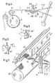
- Fig. 1 shows schematically and only partially a weaving machine, at the a goods deduction with the appearance of adverse wrinkling connected is.
- Warp threads 1 "are shown for an upper compartment as well Warp threads 2 "for a lower compartment and a sley 3 for attaching weft threads, not shown, with which together with the one hand Warp threads 1 "and on the other hand the warp threads 2" the upper fabric 1 and the Bottom fabric 2 are made. It also shows: one Stop edge 30; a rod spreader 4, which is shown in more detail in FIG. 2 is; a rod-shaped deflection element 5 'for the fabric layers 1 and 2; a Drive roller 6 and a pressure roller 7, not connected to the one depicted goods tree follows (goods tree 10 in FIG. 7).
- the rod spreader 4 the cross section of which can be seen in FIG. 2, comprises a rotatable rod 41, which is driven by the fabric layer 1, and a bearing shell 42, which is composed of two parts 42a and 42b.
- the warp threads 1 "and 2" integrated into the fabrics 1 and 2 are indicated by wavy lines 1 'and 2'.
- the upper fabric 1 moves at a speed v 1
- the lower fabric 2 at a speed v 2 .
- the fabric 1 and 2 are pressed against the bearing shell 42 by the rod 41. Since frictional forces F act between the lower fabric 2 and the bearing shell 42 and since the rod 41 makes a rotational movement corresponding to the speed v 1 , v 1 is somewhat larger than v 2 : there is therefore a displacement between the two fabrics 1 and 2. This is unfavorable
- the shift effect is most pronounced at the deflection points 421 and 422 (“stowage points”).
- the deflecting element 5 ' also contributes to the displacement effect at a "s
- Fig. 4 a deduction of goods in a weaving machine is shown, in which the method according to the invention is applied.
- the fabric 1, 2 produced with the Drive roller 6 and using suitable means from the Stop edge 30 transported away in a way that on the two layers 1 and 2 of the tissue is applied with largely symmetrical forces.
- These suitable means consist of a special spreader arrangement 4 and a deflection element 5 'designed as a pressure roller 5.
- the Fabric 1, 2 is in the spreader assembly 4 through a gap 440 between two stationary surfaces against frictional resistance pulled through.
- the gap 440 of the spreader assembly 4 lies between a rod 43 and a support shell 44, which is, for example, trough-shaped.
- the Tissue 1, 2 is held down with the rod 43 and rounded Deflection edges 441 and 442 of the support shell 44 are pressed.
- the support shell 44 has a concave shape in the effective area of the rod 43 and is of such a shape trained that their shape in a complementary manner to the shape of the Rod 43 including overlying fabric 1, 2 fits.
- the convex formed deflection edges 441 and 442 form the entrance or Exit area of the gap 440 so that the tissue 1, 2 at the entrance and is transported horizontally at the exit.
- the rod 43 is so strongly after pressed down that the between the upper fabric 1 and the rod 43 acting friction about the same as that between the lower tissues 2 and the support shell 44 is acting friction.
- the lower fabric 2 must do not touch the concave central area of the support shell 44.
- the pressure roller 5 is operatively connected to the drive roller 6:
- the pressure roller 5 is arranged with respect to the drive roller 6 so that the fabric 1, 2 on the pressure roller 5 along this one Contact angle of at least 170 ° is in contact.
- a torque is from the drive roller 6 to the pressure roller 5 over the in between lying tissue 1, 2 exercised. Because of this arrangement, the Pressure roller 5 from a drive point 51 with a tensile force on the Lower fabric 2 a; the drive roller 6 acts from a drive point 61 with a tensile force on the upper fabric 2.
- the pressure roller 5 is with Advantage so strongly pressed against the drive roller 6 that the two mentioned tensile forces are largely the same.
- the value of the The wrap angle on the pressure roller 5 is advantageously in the range between 170 ° and 190 °.
- FIGS. 5 and 6 represent two variant forms of the spreader arrangement 4
- the gap 440 is in each case by the Rod 43 and a profile rod 44 'with only one deflection edge 441' or a profile rod 44 "with deflection edge 441" is formed.
- the rod too 43 set up so that its position is adjustable. The setting can be made in both the vertical and horizontal directions.
- FIG. 7 is a partial illustration of the weaving machine from FIG. 4.
- the spreader assembly 4 the fabric 1, 2 with lateral Spreader bars 45 extend transversely to the transport direction.
- the warp threads 1 "and 2" are moved with shafts 8.
- a double weave can be created that in the warp direction on the one hand laterally and on the other hand in periodic Spaces closed areas, so that from the product rectangular bags or hollow fabric sections, especially rectangular ones Airbags that can be produced. Folds as they are with the weaving machine of FIG. 1 7 do not arise with the weaving machine shown in FIG correct attitude - or are significantly weaker.
- FIG. 8 shows a first product of the method according to the invention in schematic representation, from which rectangular sacks or Hollow tissue sections can be produced.
- 9 shows a second product for the production of round sacks or hollow fabric sections.
- the warp threads Use a jacquard machine and / or another Shed forming device moves.
Landscapes
- Engineering & Computer Science (AREA)
- Textile Engineering (AREA)
- Air Bags (AREA)
Abstract
Description
- Fig. 1
- eine schematisch und nur zu einem Teil dargestellte Webmaschine mit Durchführung eines Warenabzugs, bei dem eine nachteilige Faltenbildung auftritt,
- Fig. 2
- einen Querschnitt durch einen Stabbreithalter, der in der Webmaschine der Fig. 1 eingesetzt ist,
- Fig. 3
- zwei Längsschnitte durch Airbags, die aus Doppellagengewebe hergestellt sind,
- Fig. 4
- einen Warenabzug in einer Webmaschine, der unter Verwendung einer Breithalteranordnung gemäss dem erfindungsgemässen Verfahren durchgeführt wird,
- Fig. 5, 6
- zwei variante Formen der Breithalteranordnung,
- Fig. 7
- eine teilweise Darstellung der Webmaschine von Fig. 4,
- Fig. 8
- ein erstes Erzeugnis des erfindungsgemässen Verfahrens, aus dem rechteckige Säcke oder Hohlgewebeabschnitte herstellbar sind, und
- Fig. 9
- ein zweites Erzeugnis zur Herstellung von runden Säcken oder von Hohlgewebeabschnitten.
Claims (10)
- Verfahren zum Weben eines Doppellagengewebes (1, 2), insbesondere eines Airbag-Gewebes, mit einer Webmaschine, die zwischen Weblade (3) und Warenbaum (10) eine Breithalteranordnung (4), die unmittelbar nach einer Anschlagkante (30) angeordnet ist, ein Umlenkelement (5') für das Gewebe (1, 2) und eine Antriebswalze (6) umfasst, wobei mit der Antriebswalze und unter Verwendung geeigneter Mittel das erzeugte Gewebe von der Anschlagkante in einer Weise wegtransportiert wird, dass auf die beiden Lagen des Gewebes - auf das Untergewebe (2) bzw. Obergewebe (1) - mit weitgehend symmetrischen Kräften eingewirkt wird, nämlich indem das Gewebe in der Breithalteranordnung durch einen Spalt (440) zwischen zwei stationären Flächen entgegen Reibungswiderständen durchgezogen, gleichzeitig mit seitlichen Breithaltern (45) quer zur Transportrichtung gestreckt und mit einer drehbaren, zusätzlich zur Antriebswalze eingesetzten Anpresswalze (5) angetrieben wird, wobei die Anpresswalze, die das Umlenkelement bildet, in Wirkverbindung mit der Antriebswalze steht.
- Verfahren nach Anspruch 1, dadurch gekennzeichnet, dass der Spalt (440) zwischen einer Stange (43) und mindestens einer raumfesten Umlenkkante (441, 442; 441'; 441") angeordnet ist und dass die Position der Stange bezüglich der Umlenkkante einstellbar ist.
- Verfahren nach Anspruch 2, dadurch gekennzeichnet, dass der Spalt (440) durch eine Stange (43) und eine Auflageschale (44) gebildet ist, dass das Gewebe (1, 2) mit der Stange niedergehalten und auf zwei Umlenkkanten (441, 442) der Auflageschale gedrückt wird und dass insbesondere die Auflageschale zwischen den Umlenkkanten trogförmig sowie in einer komplementären Weise zur Stange inklusive aufliegendem Gewebe ausgebildet ist.
- Verfahren nach Anspruch 3, dadurch gekennzeichnet, dass die Auflageschale (44) im Eingangs- und Ausgangsbereich des Spalts (440) ausserhalb eines konkaven Mittelbereichs konvex ausgebildet ist, so dass das Gewebe (1, 2) am Eingang und am Ausgang jeweils horizontal transportiert wird.
- Verfahren nach einem der Ansprüche 1 bis 4, dadurch gekennzeichnet, dass die Anpresswalze (5) bezüglich der Antriebswalze (6) so angeordnet ist, dass das Gewebe (1, 2) auf der Anpresswalze mit einem Umschlingungswinkel von mindestens 170° in Kontakt steht und dass ein Drehmoment von der Antriebswalze auf die Anpresswalze über das dazwischen liegende Gewebe ausgeübt wird.
- Verfahren nach Anspruch 5, dadurch gekennzeichnet, dass das Drehmoment so gross ist, dass durch die Anpresswalze (5) das Untergewebe (2) mit einer Zugkraft angetrieben wird, die weitgehend gleich gross ist wie die durch die Antriebswalze (6) auf das Obergewebe (1) ausgeübte Zugkraft.
- Verfahren nach Anspruch 5 oder 6, dadurch gekennzeichnet, dass der Wert des Umschlingungswinkels im Bereich zwischen 170° und 190° liegt.
- Anwendung des Verfahrens gemäss einem der Ansprüche 1 bis 7 zur Herstellung von Säcken, insbesondere von Airbags, oder von Hohlgewebeabschnitten.
- Anwendung nach Anspruch 8, dadurch gekennzeichnet, dass Kettfäden (1", 2") mit Schäften (8) bewegt werden, die von einer Schaft- oder Exzentermaschine gesteuert werden, und dass ein Doppellagengewebe (1, 2) erzeugt wird, das in Kettrichtung seitlich und in periodischen Abständen geschlossene Teilflächen (12) aufweist, so dass aus dem Erzeugnis rechteckige Säcke herstellbar sind.
- Anwendung nach Anspruch 8, dadurch gekennzeichnet, dass Kettfäden (1", 2") unter Verwendung einer Jacquardmaschine bewegt werden und dass ein Doppellagengewebe (1, 2) erzeugt wird, das runde, geschlossene Randzonen (12) aufweist, so dass aus dem Erzeugnis runde Säcke herstellbar sind.
Priority Applications (1)
| Application Number | Priority Date | Filing Date | Title |
|---|---|---|---|
| EP20020405850 EP1308546B1 (de) | 2001-11-01 | 2002-10-02 | Verfahren zum Weben eines Doppellagengewebes |
Applications Claiming Priority (3)
| Application Number | Priority Date | Filing Date | Title |
|---|---|---|---|
| EP01811061 | 2001-11-01 | ||
| EP01811061 | 2001-11-01 | ||
| EP20020405850 EP1308546B1 (de) | 2001-11-01 | 2002-10-02 | Verfahren zum Weben eines Doppellagengewebes |
Publications (2)
| Publication Number | Publication Date |
|---|---|
| EP1308546A1 true EP1308546A1 (de) | 2003-05-07 |
| EP1308546B1 EP1308546B1 (de) | 2008-07-09 |
Family
ID=26077433
Family Applications (1)
| Application Number | Title | Priority Date | Filing Date |
|---|---|---|---|
| EP20020405850 Expired - Lifetime EP1308546B1 (de) | 2001-11-01 | 2002-10-02 | Verfahren zum Weben eines Doppellagengewebes |
Country Status (1)
| Country | Link |
|---|---|
| EP (1) | EP1308546B1 (de) |
Cited By (8)
| Publication number | Priority date | Publication date | Assignee | Title |
|---|---|---|---|---|
| US7798179B2 (en) | 2008-10-24 | 2010-09-21 | Groz-Beckert Kg | Spreader with clamping and ventilating devices |
| CN102926113A (zh) * | 2012-11-21 | 2013-02-13 | 常熟市宝沣特种纤维有限公司 | 有梭织机的圆筒布内撑幅装置 |
| CN107723904A (zh) * | 2017-11-14 | 2018-02-23 | 无锡市鼎麒新材料科技有限公司 | 展宽展薄布织机的经纱张力机构及其方法 |
| CN109142120A (zh) * | 2018-08-16 | 2019-01-04 | 浙江中正检测技术服务有限公司 | 一种自动式纺织品耐磨检测装置 |
| CN113417054A (zh) * | 2021-07-15 | 2021-09-21 | 鲁丰织染有限公司 | 解决接结双层面料织造分层不一致的方法 |
| CN113564785A (zh) * | 2021-08-09 | 2021-10-29 | 江苏佩捷纺织智能科技有限公司 | 一种带辅助撑开的宽幅织机转动导布辊装置 |
| DE102021208496A1 (de) | 2020-08-17 | 2022-02-17 | Tesa Se | Klebeband zum Ummanteln von langgestrecktem Gut wie insbesondere Kabelsätzen und Verfahren zur Ummantelung |
| DE102021210866A1 (de) | 2021-09-28 | 2023-03-30 | Tesa Se | Klebeband zum Ummanteln von langgestrecktem Gut wie insbesondere Kabelsätzen und Verfahren zur Ummantelung |
Citations (11)
| Publication number | Priority date | Publication date | Assignee | Title |
|---|---|---|---|---|
| DE2222474A1 (de) * | 1971-05-07 | 1972-11-30 | Vyzk A Vyv Ustav Zd U Vsheobec | Gewebe-Breithaltevorrichtung an Webmaschinen |
| DE2328244A1 (de) * | 1972-06-12 | 1974-01-03 | Vyzk Ustav Bavlnarsky | Verfahren zur stabilisierung des gewebes im bereich des schussfadenanschlags bei wellenfachwebmaschinen und vorrichtung zur durchfuehrung dieses verfahrens |
| JPS55132746A (en) | 1979-04-04 | 1980-10-15 | Nissan Motor | Warp fluff preventing apparatus of loom |
| DE4038287A1 (de) * | 1989-12-01 | 1991-06-06 | Takata Corp | Basisstoff fuer airbag |
| SU1703731A1 (ru) * | 1990-01-17 | 1992-01-07 | Ленинградский институт текстильной и легкой промышленности им.С.М.Кирова | Товарный регул тор ткацкого станка |
| JPH0527084U (ja) | 1991-09-20 | 1993-04-06 | 日産自動車株式会社 | 織機の織布巻き取り装置 |
| JPH05239741A (ja) | 1991-05-13 | 1993-09-17 | Tsudakoma Corp | 織機の口合せ段防止方法 |
| JPH0712489U (ja) | 1993-07-30 | 1995-02-28 | 津田駒工業株式会社 | テンプル姿勢調節機構 |
| US5651395A (en) * | 1989-02-16 | 1997-07-29 | Airbags International Limited | Circular air bag made of two simultaneously woven fabrics |
| WO1998051845A1 (de) | 1997-05-11 | 1998-11-19 | Buesgen Alexander | Gewebe mit veränderlicher breite |
| JPH11107135A (ja) * | 1997-09-30 | 1999-04-20 | Tsudakoma Corp | 巻取装置 |
-
2002
- 2002-10-02 EP EP20020405850 patent/EP1308546B1/de not_active Expired - Lifetime
Patent Citations (12)
| Publication number | Priority date | Publication date | Assignee | Title |
|---|---|---|---|---|
| DE2222474A1 (de) * | 1971-05-07 | 1972-11-30 | Vyzk A Vyv Ustav Zd U Vsheobec | Gewebe-Breithaltevorrichtung an Webmaschinen |
| US3771573A (en) | 1971-05-07 | 1973-11-13 | Vyzk Vyvojovy Ustav Z Vseob St | Fabric expanding device for weaving machines |
| DE2328244A1 (de) * | 1972-06-12 | 1974-01-03 | Vyzk Ustav Bavlnarsky | Verfahren zur stabilisierung des gewebes im bereich des schussfadenanschlags bei wellenfachwebmaschinen und vorrichtung zur durchfuehrung dieses verfahrens |
| JPS55132746A (en) | 1979-04-04 | 1980-10-15 | Nissan Motor | Warp fluff preventing apparatus of loom |
| US5651395A (en) * | 1989-02-16 | 1997-07-29 | Airbags International Limited | Circular air bag made of two simultaneously woven fabrics |
| DE4038287A1 (de) * | 1989-12-01 | 1991-06-06 | Takata Corp | Basisstoff fuer airbag |
| SU1703731A1 (ru) * | 1990-01-17 | 1992-01-07 | Ленинградский институт текстильной и легкой промышленности им.С.М.Кирова | Товарный регул тор ткацкого станка |
| JPH05239741A (ja) | 1991-05-13 | 1993-09-17 | Tsudakoma Corp | 織機の口合せ段防止方法 |
| JPH0527084U (ja) | 1991-09-20 | 1993-04-06 | 日産自動車株式会社 | 織機の織布巻き取り装置 |
| JPH0712489U (ja) | 1993-07-30 | 1995-02-28 | 津田駒工業株式会社 | テンプル姿勢調節機構 |
| WO1998051845A1 (de) | 1997-05-11 | 1998-11-19 | Buesgen Alexander | Gewebe mit veränderlicher breite |
| JPH11107135A (ja) * | 1997-09-30 | 1999-04-20 | Tsudakoma Corp | 巻取装置 |
Non-Patent Citations (1)
| Title |
|---|
| PATENT ABSTRACTS OF JAPAN vol. 1999, no. 09 30 July 1999 (1999-07-30) * |
Cited By (12)
| Publication number | Priority date | Publication date | Assignee | Title |
|---|---|---|---|---|
| US7798179B2 (en) | 2008-10-24 | 2010-09-21 | Groz-Beckert Kg | Spreader with clamping and ventilating devices |
| CN102926113A (zh) * | 2012-11-21 | 2013-02-13 | 常熟市宝沣特种纤维有限公司 | 有梭织机的圆筒布内撑幅装置 |
| CN107723904A (zh) * | 2017-11-14 | 2018-02-23 | 无锡市鼎麒新材料科技有限公司 | 展宽展薄布织机的经纱张力机构及其方法 |
| CN109142120A (zh) * | 2018-08-16 | 2019-01-04 | 浙江中正检测技术服务有限公司 | 一种自动式纺织品耐磨检测装置 |
| DE102021208496A1 (de) | 2020-08-17 | 2022-02-17 | Tesa Se | Klebeband zum Ummanteln von langgestrecktem Gut wie insbesondere Kabelsätzen und Verfahren zur Ummantelung |
| EP3957695A1 (de) | 2020-08-17 | 2022-02-23 | tesa SE | Klebeband zum ummanteln von langgestrecktem gut wie insbesondere kabelsätzen und verfahren zur ummantelung |
| US12187926B2 (en) | 2020-08-17 | 2025-01-07 | Tesa Se | Adhesive tape for jacketing elongate items such as especially cable harnesses and methods for jacketing |
| CN113417054A (zh) * | 2021-07-15 | 2021-09-21 | 鲁丰织染有限公司 | 解决接结双层面料织造分层不一致的方法 |
| CN113564785A (zh) * | 2021-08-09 | 2021-10-29 | 江苏佩捷纺织智能科技有限公司 | 一种带辅助撑开的宽幅织机转动导布辊装置 |
| DE102021210866A1 (de) | 2021-09-28 | 2023-03-30 | Tesa Se | Klebeband zum Ummanteln von langgestrecktem Gut wie insbesondere Kabelsätzen und Verfahren zur Ummantelung |
| WO2023052251A1 (de) | 2021-09-28 | 2023-04-06 | Tesa Se | Klebeband zum Ummanteln von langgestrecktem Gut wie insbesondere Kabelsätzen und Verfahren zur Ummantelung |
| EP4450576A1 (de) | 2021-09-28 | 2024-10-23 | Tesa Se | Klebeband zum Ummanteln von langgestrecktem Gut wie insbesondere Kabelsätzen und Verfahren zur Ummantelung |
Also Published As
| Publication number | Publication date |
|---|---|
| EP1308546B1 (de) | 2008-07-09 |
Similar Documents
| Publication | Publication Date | Title |
|---|---|---|
| DE2148401A1 (de) | Fuellbare hohlartikel aus mit gummi oder gummiersatzstoffen beschichteten geweben | |
| DE69407365T2 (de) | Naht mit hoher schlingendichte | |
| DE2435376A1 (de) | Papiermaschinenfilz bzw. -tuch und verfahren zu seiner herstellung | |
| DE3036409A1 (de) | Doppellagiges sieb fuer den blattbildungsteil einer papiermaschine | |
| DD287542A5 (de) | Bauteil auf gewirkebasis und verfahren zu seiner herstellung | |
| CH637707A5 (de) | Webblatt fuer eine duesenwebmaschine. | |
| WO2019063518A1 (de) | Bespannung | |
| EP1308546B1 (de) | Verfahren zum Weben eines Doppellagengewebes | |
| DE2263476B2 (de) | Gewebe für Papiermaschinensiebe | |
| DE60318265T3 (de) | Grundgewebe für Papiermacherpressfilz und Papiermacherpressfilz | |
| DE4229828A1 (de) | Papiermaschinensieb in Form eines Verbundgewebes | |
| DE2046845C3 (de) | Gewebeschalung | |
| WO2001034888A1 (de) | Verfahren und einrichtung zum herstellen von etiketten | |
| DE69813725T2 (de) | Band für eine Schuhpresse und Verfahren zu seiner Herstellung | |
| DE10224771A1 (de) | Gassack und Verfahren zum Herstellen eines Gassacks | |
| EP1370167B1 (de) | Bandkombination zur positionierung von latten in einem lattenrost | |
| DE102005022505B4 (de) | Rollobahn | |
| DE2028582C3 (de) | Auf Zug beanspruchbares Gewebeprodukt | |
| DE102006017270A1 (de) | Gewebe | |
| DE916882C (de) | Vorrichtung fuer Kleidungsstuecke zur Verhinderung des Aufrollens | |
| DE10056837A1 (de) | Basistextilerzeugnis für Airbags | |
| EP0579938B1 (de) | Verfahren zur Herstellung eines Gurtbandes und in diesem Verfahren hergestelltes Gurtband | |
| DE1912749C3 (de) | Luftmatratze | |
| DE60312585T2 (de) | Zierband | |
| DE19713812C2 (de) | Textilgebilde |
Legal Events
| Date | Code | Title | Description |
|---|---|---|---|
| PUAI | Public reference made under article 153(3) epc to a published international application that has entered the european phase |
Free format text: ORIGINAL CODE: 0009012 |
|
| AK | Designated contracting states |
Designated state(s): AT BE BG CH CY CZ DE DK EE ES FI FR GB GR IE IT LI LU MC NL PT SE SK TR |
|
| AX | Request for extension of the european patent |
Extension state: AL LT LV MK RO SI |
|
| 17P | Request for examination filed |
Effective date: 20031009 |
|
| AKX | Designation fees paid |
Designated state(s): BE DE IT |
|
| TPAC | Observations filed by third parties |
Free format text: ORIGINAL CODE: EPIDOSNTIPA |
|
| 17Q | First examination report despatched |
Effective date: 20060913 |
|
| 17Q | First examination report despatched |
Effective date: 20060913 |
|
| GRAP | Despatch of communication of intention to grant a patent |
Free format text: ORIGINAL CODE: EPIDOSNIGR1 |
|
| GRAS | Grant fee paid |
Free format text: ORIGINAL CODE: EPIDOSNIGR3 |
|
| GRAA | (expected) grant |
Free format text: ORIGINAL CODE: 0009210 |
|
| AK | Designated contracting states |
Kind code of ref document: B1 Designated state(s): BE DE IT |
|
| REF | Corresponds to: |
Ref document number: 50212466 Country of ref document: DE Date of ref document: 20080821 Kind code of ref document: P |
|
| PLBE | No opposition filed within time limit |
Free format text: ORIGINAL CODE: 0009261 |
|
| STAA | Information on the status of an ep patent application or granted ep patent |
Free format text: STATUS: NO OPPOSITION FILED WITHIN TIME LIMIT |
|
| 26N | No opposition filed |
Effective date: 20090414 |
|
| PGFP | Annual fee paid to national office [announced via postgrant information from national office to epo] |
Ref country code: IT Payment date: 20100819 Year of fee payment: 9 |
|
| PGFP | Annual fee paid to national office [announced via postgrant information from national office to epo] |
Ref country code: DE Payment date: 20101022 Year of fee payment: 9 |
|
| PGFP | Annual fee paid to national office [announced via postgrant information from national office to epo] |
Ref country code: BE Payment date: 20101013 Year of fee payment: 9 |
|
| BERE | Be: lapsed |
Owner name: SULTEX A.G. Effective date: 20111031 |
|
| PG25 | Lapsed in a contracting state [announced via postgrant information from national office to epo] |
Ref country code: BE Free format text: LAPSE BECAUSE OF NON-PAYMENT OF DUE FEES Effective date: 20111031 Ref country code: DE Free format text: LAPSE BECAUSE OF NON-PAYMENT OF DUE FEES Effective date: 20120501 |
|
| REG | Reference to a national code |
Ref country code: DE Ref legal event code: R119 Ref document number: 50212466 Country of ref document: DE Effective date: 20120501 |
|
| PG25 | Lapsed in a contracting state [announced via postgrant information from national office to epo] |
Ref country code: IT Free format text: LAPSE BECAUSE OF NON-PAYMENT OF DUE FEES Effective date: 20111002 |