EP1308407A2 - Einrichtung zum Erfassen der Lage einer Kante eines durchsichtigen Verarbeitungsgutes - Google Patents
Einrichtung zum Erfassen der Lage einer Kante eines durchsichtigen Verarbeitungsgutes Download PDFInfo
- Publication number
- EP1308407A2 EP1308407A2 EP02023702A EP02023702A EP1308407A2 EP 1308407 A2 EP1308407 A2 EP 1308407A2 EP 02023702 A EP02023702 A EP 02023702A EP 02023702 A EP02023702 A EP 02023702A EP 1308407 A2 EP1308407 A2 EP 1308407A2
- Authority
- EP
- European Patent Office
- Prior art keywords
- edge
- measuring device
- optoelectric
- inclination
- feed table
- Prior art date
- Legal status (The legal status is an assumption and is not a legal conclusion. Google has not performed a legal analysis and makes no representation as to the accuracy of the status listed.)
- Ceased
Links
Images


Classifications
-
- B—PERFORMING OPERATIONS; TRANSPORTING
- B65—CONVEYING; PACKING; STORING; HANDLING THIN OR FILAMENTARY MATERIAL
- B65H—HANDLING THIN OR FILAMENTARY MATERIAL, e.g. SHEETS, WEBS, CABLES
- B65H7/00—Controlling article feeding, separating, pile-advancing, or associated apparatus, to take account of incorrect feeding, absence of articles, or presence of faulty articles
- B65H7/02—Controlling article feeding, separating, pile-advancing, or associated apparatus, to take account of incorrect feeding, absence of articles, or presence of faulty articles by feelers or detectors
- B65H7/14—Controlling article feeding, separating, pile-advancing, or associated apparatus, to take account of incorrect feeding, absence of articles, or presence of faulty articles by feelers or detectors by photoelectric feelers or detectors
-
- B—PERFORMING OPERATIONS; TRANSPORTING
- B65—CONVEYING; PACKING; STORING; HANDLING THIN OR FILAMENTARY MATERIAL
- B65H—HANDLING THIN OR FILAMENTARY MATERIAL, e.g. SHEETS, WEBS, CABLES
- B65H2511/00—Dimensions; Position; Numbers; Identification; Occurrences
- B65H2511/20—Location in space
- B65H2511/23—Coordinates, e.g. three dimensional coordinates
-
- B—PERFORMING OPERATIONS; TRANSPORTING
- B65—CONVEYING; PACKING; STORING; HANDLING THIN OR FILAMENTARY MATERIAL
- B65H—HANDLING THIN OR FILAMENTARY MATERIAL, e.g. SHEETS, WEBS, CABLES
- B65H2511/00—Dimensions; Position; Numbers; Identification; Occurrences
- B65H2511/50—Occurence
- B65H2511/51—Presence
- B65H2511/514—Particular portion of element
-
- B—PERFORMING OPERATIONS; TRANSPORTING
- B65—CONVEYING; PACKING; STORING; HANDLING THIN OR FILAMENTARY MATERIAL
- B65H—HANDLING THIN OR FILAMENTARY MATERIAL, e.g. SHEETS, WEBS, CABLES
- B65H2515/00—Physical entities not provided for in groups B65H2511/00 or B65H2513/00
- B65H2515/60—Optical characteristics, e.g. colour, light
-
- B—PERFORMING OPERATIONS; TRANSPORTING
- B65—CONVEYING; PACKING; STORING; HANDLING THIN OR FILAMENTARY MATERIAL
- B65H—HANDLING THIN OR FILAMENTARY MATERIAL, e.g. SHEETS, WEBS, CABLES
- B65H2553/00—Sensing or detecting means
- B65H2553/40—Sensing or detecting means using optical, e.g. photographic, elements
- B65H2553/41—Photoelectric detectors
- B65H2553/414—Photoelectric detectors involving receptor receiving light reflected by a reflecting surface and emitted by a separate emitter
-
- B—PERFORMING OPERATIONS; TRANSPORTING
- B65—CONVEYING; PACKING; STORING; HANDLING THIN OR FILAMENTARY MATERIAL
- B65H—HANDLING THIN OR FILAMENTARY MATERIAL, e.g. SHEETS, WEBS, CABLES
- B65H2701/00—Handled material; Storage means
- B65H2701/10—Handled articles or webs
- B65H2701/13—Parts concerned of the handled material
- B65H2701/131—Edges
-
- B—PERFORMING OPERATIONS; TRANSPORTING
- B65—CONVEYING; PACKING; STORING; HANDLING THIN OR FILAMENTARY MATERIAL
- B65H—HANDLING THIN OR FILAMENTARY MATERIAL, e.g. SHEETS, WEBS, CABLES
- B65H2701/00—Handled material; Storage means
- B65H2701/10—Handled articles or webs
- B65H2701/13—Parts concerned of the handled material
- B65H2701/131—Edges
- B65H2701/1315—Edges side edges, i.e. regarded in context of transport
-
- B—PERFORMING OPERATIONS; TRANSPORTING
- B65—CONVEYING; PACKING; STORING; HANDLING THIN OR FILAMENTARY MATERIAL
- B65H—HANDLING THIN OR FILAMENTARY MATERIAL, e.g. SHEETS, WEBS, CABLES
- B65H2701/00—Handled material; Storage means
- B65H2701/10—Handled articles or webs
- B65H2701/17—Nature of material
- B65H2701/171—Physical features of handled article or web
- B65H2701/1712—Transparent
Definitions
- the invention relates to a device for detecting the position of an edge of a transparent Processing goods that are fed to a printing press with an optoelectric Measuring device that consists of at least one reflex line, which serves as a contrast-enhancing Means a reflective film or reflective layer is assigned.
- the printing material can be in the form of a web or sheet, and this made of different materials, e.g. Paper, cardboard, sheet metal or a clear Processing goods can exist.
- an optoelectric measuring device as a reflex line train and with this the actual position of a ribbon or sheet-shaped processing goods capture.
- the reflex line is at a distance above the material to be processed arranged.
- the edge to be detected forms a light / dark jump on the reflex line from which a signal is generated which is used to determine the actual position the edge of a processing electronics is supplied.
- a contrast-enhancing agent is assigned to the reflex line. This contrast-enhancing Mean is e.g. provided in the feed table and the reflex line arranged perpendicular to it.
- the object of the invention is to change a known device with simple means so that the position of the edge of a transparent material to be processed is reliably detected can be.
- the object is achieved by a device according to the features of the claim 1 solved.
- the solution according to the invention makes it possible to ensure with simple means that that even when processing transparent processing goods, the data to be recorded Edge is contoured on a receiver so that the exact position of the edge reproducing signal can be generated.
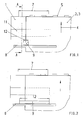
- a feed table 1 with processing goods 2, which is designed as a sheet 3, is shown.
- the sheets 3 are transported in the conveying direction 4 on the feed table 1 and with the front edge against front marks 5.
- a traverse 8 is provided which extends over at least one format difference area 7 which is characteristic of the respective printing press.
- the format difference area 7 is formed from the difference between the maximum and the minimum format of the sheets 3 to be processed, so that the sheet 3 each has a format difference area 7 on both sides.
- the traverse 8 is arranged fixed to the frame.
- a housing 9 with a reflex line 10 is slidably provided on the traverse 8.
- the reflex line 10 consists in a known manner of an illumination device, which is designed, for example, as an LED line and a CCD line, which consists of a plurality of measuring elements arranged in a row next to one another.
- Light rays 13 are emitted by the illumination device of the reflex line 10 and extend at an angle of inclination ⁇ to the surface of the feed table 1 and thus also to the surface of the sheet 3 to be aligned.
- an insert 11 is interchangeably mounted in the feed table 1 such that the surface of the insert 11 forms a plane with the surface of the feed table 1.
- the surface of the insert 11 is provided with a reflective layer or with a reflective film.
- the reflective layer or the reflective film has the property of diffusely reflecting incident light or, in contrast to a regular reflection, sending the light back to the light source in the event of an oblique incidence.
- the light beams 13 emitted by the reflex line 10 strike the surface of the sheet 3 made of a transparent material as well as the outside of the sheet 3 and the reflection layer or foil of the insert 11 at the angle of inclination ⁇ .
- the rays impinging on the surface of the transparent sheet 3 are regularly reflected according to the law of reflection, while the light rays 13 appearing on the reflective layer or the reflective film are returned to the reflective line 10.
- the edge 6 forms on the reflex line 10 as a light / dark jump, by means of which a signal which reflects the actual position of the edge 6 is generated.
- This actual signal is fed to processing electronics, not shown, in which a desired signal characterizing the desired position of the sheet 3 is stored.
- the setpoint signal is compared with the actual signal in the processing electronics and an actuating signal is generated in the event of a deviation.
- the control signal is fed to control elements by means of which the edge 6 of the sheet 3 is brought from the actual position into the desired position.
- the angle of inclination ⁇ can move in a range of 90 ° ⁇ > 5 °. It is therefore possible to make the cross member 8 and or the housing 9 adjustable so that the angle of inclination ⁇ is adjustable.
- the reflex line 10 and the associated reflection layer or foil are provided above or on the feed table 1. It is also possible to arrange the reflex line 10 below the feed table 1 in such a way that the light beams 13 are emitted at the angle of inclination ⁇ and pass through a recess provided in the feed table 1 and closed with a transparent cover. Adapted to the course of the light beams 13, the reflective layer or reflective film is arranged above the feed table 1, for example on a crossmember 8, so that the rays striking the reflective layer or reflective film are also sent back differently from the regular reflection to the reflective line and the position of the reflective line thereon Edge 6 is mapped.
Landscapes
- Length Measuring Devices By Optical Means (AREA)
- Controlling Sheets Or Webs (AREA)
- Inking, Control Or Cleaning Of Printing Machines (AREA)
Abstract
Description
- Fig. 1
- eine Draufsicht auf einen Anlegtisch mit einer die Lage einer Kante erfassenden Einrichtung,
- Fig. 2
- eine Ansicht gem. Fig. 1 mit einer anderen Ausführungsform,
- Fig. 3
- eine Schnittdarstellung entlang der Linie A-A in Fig. 1,
- Fig. 4
- eine räumliche Darstellung gem. Fig. 1.
Die Traverse 8 ist gestellfest angeordnet. An der Traverse 8 ist verschiebbar ein Gehäuse 9 mit einer Reflexzeile 10 vorgesehen. Die Reflexzeile 10 besteht in bekannter Weise aus einer Beleuchtungseinrichtung, die z.B. als LED-Zeile ausgebildet ist und einer CCD-Zeile, die aus einer Vielzahl von in einer Reihe nebeneinander angeordneten Messelementen besteht. Durch die Beleuchtungseinrichtung der Reflexzeile 10 werden Lichtstrahlen 13 emittiert, die unter einem Neigungswinkel α zur Oberfläche des Anlegtischs 1 und damit auch zur Oberfläche des jeweils auszurichtenden Bogens 3 verlaufen. In dem Bereich, in dem die Lichtstrahlen 13 der Reflexzeile 10 auf den Anlegtisch 1 auftreffen, ist ein Einsatzstück 11 im Anlegtisch 1 so auswechselbar gelagert, dass die Oberfläche des Einsatzstücks 11 mit der Oberfläche des Anlegtischs 1 eine Ebene bildet. Die Oberfläche des Einsatzstücks 11 ist mit einer Reflexionsschicht oder mit einer Reflexionsfolie versehen. Die Reflexionsschicht oder die Reflexionsfolie hat die Eigenschaft, einfallendes Licht diffus zu reflektieren bzw. abweichend von einer regulären Reflexion das Licht bei einem schrägen Einfall zur Lichtquelle zurückzusenden.
Wie in Fig. 4 gezeigt, treffen die von der Reflexzeile 10 emittierten Lichtstrahlen 13 unter dem Neigungswinkel α sowohl auf die Oberfläche des aus einem durchsichtigen Material bestehenden Bogens 3 als auch außerhalb des Bogens 3 auf die Reflexionsschicht oder Reflexionsfolie des Einsatzstücks 11 auf. Die auf der Oberfläche des durchsichtigen Bogens 3 auftreffenden Strahlen werden regulär nach dem Reflexionsgesetz reflektiert, während die auf die Reflexionsschicht oder die Reflexionsfolie auftretenden Lichtstrahlen 13 zur Reflexzeile 10 zurückgeführt werden. Dadurch bildet sich die Kante 6 auf der Reflexzeile 10 als Hell-/Dunkelsprung ab, durch den ein die Istlage der Kante 6 wiedergebendes Signal generiert wird. Dieses Istsignal wird einer nicht dargestellten Verarbeitungselektrik zugeführt, in der ein die Solllage des Bogens 3 charakterisierendes Sollsignal abgelegt ist. In der Verarbeitungselektronik wird das Sollsignal mit dem Istsignal verglichen und bei einer Abweichung ein Stellsignal generiert. Das Stellsignal wird Stellelementen zugeführt, durch welche die Kante 6 des Bogens 3 aus der Istlage in die Solllage verbracht wird. Der Neigungswinkel α kann sich in einem Bereich 90° < α > 5° bewegen. Es ist deshalb möglich, die Traverse 8 und oder das Gehäuse 9 so verstellbar auszuführen, dass der Neigungswinkel α einstellbar ausgeführt ist.
In den Figuren 1 bis 4 sind die Reflexzeile 10 und die zugehörige Reflexionsschicht oder Reflexionsfolie oberhalb bzw. auf dem Anlegtisch 1 vorgesehen. Es ist auch möglich, die Reflexzeile 10 unterhalb des Anlegtischs 1 so anzuordnen, dass die Lichtstahlen 13 unter dem Neigungswinkel α emittiert werden und durch eine im Anlegtisch 1 vorgesehene, mit einer durchsichtigen Abdeckung verschlossene Aussparung treten. Dem Verlauf der Lichtstrahlen 13 angepasst, ist oberhalb des Anlegtischs 1 die Reflexschicht oder Reflexfolie z.B. an einer Traverse 8 angeordnet, so dass ebenfalls die auf die Reflexionsschicht oder Reflexionsfolie treffenden Strahlen abweichend von der regulären Reflexion zur Reflexzeile zurückgesandt werden und so auf dieser die Lage der Kante 6 abgebildet wird.
- 1
- Anlegtisch
- 2
- Verarbeitungsgut
- 3
- Bogen
- 4
- Förderrichtung
- 5
- Vordermarke
- 6
- Kante
- 7
- Formatdifferenzbereich
- 8
- Traverse
- 9
- Gehäuse
- 10
- Reflexzeile
- 11
- Einsatzstück
- 12
- Messbereich
- 13
- Lichtstrahl
- α
- Neigungswinkel
Claims (6)
- Einrichtung zum Erfassen der Lage einer Kante eines durchsichtigen Verarbeitungsgutes, das einer Druckmaschine zugeführt wird, mit einer optoelektrischen Messeinrichtung, die mindestens aus einer Reflexionszeile besteht, welcher als kontrastunterstützendes Mittel eine Reflexfolie oder Reflexschicht zugeordnet ist, dadurch gekennzeichnet, dass Lichtstrahlen(13) der optoelektrischen Messeinrichtung unter einem Neigungswinkel (α) auf das Verarbeitungsgut (2) und auf die Reflexschicht oder Reflexfolie auftreffen.
- Einrichtung nach Anspruch 1, dadurch gekennzeichnet, dass der Neigungswinkel (α) in einem Bereich 90° < α > 5° liegt.
- Einrichtung nach Anspruch 1, dadurch gekennzeichnet, dass der Neigungswinkel (α) einstellbar ausgeführt ist.
- Einrichtung nach Anspruch 1, dadurch gekennzeichnet, dass die aus der Reflexionszeile (10) bestehende optoelektrische Messeinrichtung in einem Gehäuse (9) vorgesehen ist, das an einer gestellfesten Traverse (8) angeordnet ist.
- Einrichtung nach Anspruch 1 und 4, dadurch gekennzeichnet, dass das Gehäuse mit der optoelektrischen Messeinrichtung verschieb- und schwenkbar an der Traverse (8) angeordnet ist.
- Einrichtung nach Anspruch 1, dadurch gekennzeichnet, dass die optoelektrische Messeinrichtung unterhalb des Anlegtischs (1) angeordnet ist und den durch eine Aussparung im Anlegtisch (1) tretenden Lichtstrahlen (13) oberhalb des Verarbeitungsgutes (2) die Reflexschicht oder die Reflexfolie zugeordnet ist.
Applications Claiming Priority (2)
| Application Number | Priority Date | Filing Date | Title |
|---|---|---|---|
| DE10154035 | 2001-11-02 | ||
| DE10154035A DE10154035A1 (de) | 2001-11-02 | 2001-11-02 | Einrichtung zum Erfassen der Lage einer Kante eines durchsichtigen Verarbeitungsgutes |
Publications (2)
| Publication Number | Publication Date |
|---|---|
| EP1308407A2 true EP1308407A2 (de) | 2003-05-07 |
| EP1308407A3 EP1308407A3 (de) | 2004-03-17 |
Family
ID=7704511
Family Applications (1)
| Application Number | Title | Priority Date | Filing Date |
|---|---|---|---|
| EP02023702A Ceased EP1308407A3 (de) | 2001-11-02 | 2002-10-23 | Einrichtung zum Erfassen der Lage einer Kante eines durchsichtigen Verarbeitungsgutes |
Country Status (2)
| Country | Link |
|---|---|
| EP (1) | EP1308407A3 (de) |
| DE (1) | DE10154035A1 (de) |
Cited By (1)
| Publication number | Priority date | Publication date | Assignee | Title |
|---|---|---|---|---|
| US20140231216A1 (en) * | 2013-02-19 | 2014-08-21 | Kabushiki Kaisha Toshiba | Paper sheet processing apparatus |
Families Citing this family (2)
| Publication number | Priority date | Publication date | Assignee | Title |
|---|---|---|---|---|
| DE102005000705B4 (de) * | 2005-01-03 | 2011-04-14 | Klöckner Hänsel Processing GmbH | Vorrichtung und Verfahren zur Messung von Süßwarenmassen auf einem Kühlband |
| DE102007011928A1 (de) * | 2007-03-13 | 2008-09-18 | Man Roland Druckmaschinen Ag | Verfahren und Vorrichtung zur berührungslosen Stapelerfassung |
Family Cites Families (9)
| Publication number | Priority date | Publication date | Assignee | Title |
|---|---|---|---|---|
| GB1307664A (en) * | 1971-04-22 | 1973-02-21 | Polygraph Leipzig | Photo-electric sheet position detecting devices in sheet processing machines |
| DE2758532A1 (de) * | 1977-12-28 | 1979-07-05 | Agfa Gevaert Ag | Lichtschranke |
| JPS552528A (en) * | 1978-06-17 | 1980-01-10 | Minolta Camera Co Ltd | Apparatus for detecting sheet-like material to be transported |
| US4484070A (en) * | 1981-04-30 | 1984-11-20 | Canon Kabushiki Kaisha | Sheet detecting device |
| JPS589083A (ja) * | 1981-07-09 | 1983-01-19 | Toshiro Yamada | 光を用いた物体の検出方法 |
| US5075543A (en) * | 1990-05-29 | 1991-12-24 | Xerox Corporation | Light weight paper sensor using fibers |
| US5516094A (en) * | 1994-06-24 | 1996-05-14 | Xerox Corporation | Linear array sensor for copy sheet registration |
| DE19506466C1 (de) * | 1995-02-24 | 1996-09-26 | Koenig & Bauer Albert Ag | Vorrichtung zum Messen einer Lage einer Kante von Bogen |
| US6521905B1 (en) * | 1999-09-22 | 2003-02-18 | Nexpress Solutions Llc | Method and device for detecting the position of a transparent moving conveyor belt |
-
2001
- 2001-11-02 DE DE10154035A patent/DE10154035A1/de not_active Withdrawn
-
2002
- 2002-10-23 EP EP02023702A patent/EP1308407A3/de not_active Ceased
Cited By (2)
| Publication number | Priority date | Publication date | Assignee | Title |
|---|---|---|---|---|
| US20140231216A1 (en) * | 2013-02-19 | 2014-08-21 | Kabushiki Kaisha Toshiba | Paper sheet processing apparatus |
| US9290346B2 (en) * | 2013-02-19 | 2016-03-22 | Kabushiki Kaisha Toshiba | Paper sheet processing apparatus |
Also Published As
| Publication number | Publication date |
|---|---|
| EP1308407A3 (de) | 2004-03-17 |
| DE10154035A1 (de) | 2003-05-15 |
Similar Documents
| Publication | Publication Date | Title |
|---|---|---|
| DE4338780C2 (de) | Mustererkennungsvorrichtung | |
| EP2881762B1 (de) | Optoelektronischer Sensor und Verfahren zur Erfassung glänzender Objekte | |
| DE10045261A1 (de) | Verfahren und Vorrichtung zur Erfassung eines Materials sowie Steuervorrichtung für ein bewegtes Material | |
| DE19946498A1 (de) | Plattenspieler | |
| DE19909518A1 (de) | Verfahren und Vorrichtung zur Erfassung der Lage von gestapeltem Material | |
| EP1041394A2 (de) | Optoelektronische Vorrichtung | |
| EP1279919A1 (de) | Einrichtung zum Erfassen der Lage einer Kante eines Verarbeitungsgutes | |
| DE10154035A1 (de) | Einrichtung zum Erfassen der Lage einer Kante eines durchsichtigen Verarbeitungsgutes | |
| EP0513482B1 (de) | Seitenmarken- und Überziehkontrolle einer Rotations-Bogendruckmaschine | |
| EP1300354B1 (de) | Einrichtung zum Erfassen der Lage einer Kante eines Verarbeitungsgutes | |
| DE102019130572B3 (de) | Stückguterfassungsanordnung | |
| EP0690792B1 (de) | Vorrichtung zur exakten positionierung eines druckkopfs zu einem aufzeichnungsträger | |
| DE10136874A1 (de) | Einrichtung zum Erfassen der Lage einer Kante eines Verarbeitungsgutes | |
| EP1279921A2 (de) | Einrichtung zum Erfassen der Lage einer Kante eines Verarbeitungsgutes | |
| EP1308406B2 (de) | Einrichtung zum Erfassen der Position einer Seitenkante | |
| DE10136871A1 (de) | Einrichtung zum Erfassen der Lage einer Kante eines Verarbeitungsgutes | |
| DE602004011709T2 (de) | Vorrichtung zur Erkennung der Schräglage eines Dokuments | |
| EP0810970A1 (de) | Kontrolleinrichtung zur überwachung des laufes zweier übereinanderliegender papierbahnen in einer papierverarbeitungsmaschine | |
| DE102017105847B4 (de) | Anordnung und Verfahren zum Ausrichten mindestens eines Wertscheines | |
| DE20004803U1 (de) | Vorrichtung zur Detektion von Flachgutkanten | |
| DE10028523B4 (de) | Vorrichtung zum Messen der Höhe eines Bogenstapels unter Verwendung eines im Reflexbetrieb arbeitenden Strahlungsdetektors | |
| DE102008030437B4 (de) | Einrichtung zum Steuern einer Bogenzufuhr zu einer Maschine | |
| DE629138C (de) | Ausrueckvorrichtung fuer Bogen verarbeitende Maschinen | |
| DE102004022955A1 (de) | Vorrichtung und Verfahren zum Erfassen der Lage einer Kante eines Produkts | |
| DE1223681B (de) | Vorrichtung zum staendigen Aufeinanderstapeln von Bogen mit einer Absenkvorrichtung |
Legal Events
| Date | Code | Title | Description |
|---|---|---|---|
| PUAI | Public reference made under article 153(3) epc to a published international application that has entered the european phase |
Free format text: ORIGINAL CODE: 0009012 |
|
| AK | Designated contracting states |
Designated state(s): AT BE BG CH CY CZ DE DK EE ES FI FR GB GR IE IT LI LU MC NL PT SE SK TR |
|
| AX | Request for extension of the european patent |
Extension state: AL LT LV MK RO SI |
|
| PUAL | Search report despatched |
Free format text: ORIGINAL CODE: 0009013 |
|
| AK | Designated contracting states |
Kind code of ref document: A3 Designated state(s): AT BE BG CH CY CZ DE DK EE ES FI FR GB GR IE IT LI LU MC NL PT SE SK TR |
|
| AX | Request for extension of the european patent |
Extension state: AL LT LV MK RO SI |
|
| RIC1 | Information provided on ipc code assigned before grant |
Ipc: 7G 01V 8/22 B Ipc: 7B 65H 7/14 A |
|
| 17P | Request for examination filed |
Effective date: 20040205 |
|
| 17Q | First examination report despatched |
Effective date: 20040907 |
|
| AKX | Designation fees paid |
Designated state(s): DE FR GB |
|
| STAA | Information on the status of an ep patent application or granted ep patent |
Free format text: STATUS: THE APPLICATION HAS BEEN REFUSED |
|
| 18R | Application refused |
Effective date: 20050410 |