EP1306709B1 - Vorrichtung zur Strahlführung eines Laserstrahls - Google Patents
Vorrichtung zur Strahlführung eines Laserstrahls Download PDFInfo
- Publication number
- EP1306709B1 EP1306709B1 EP02023280A EP02023280A EP1306709B1 EP 1306709 B1 EP1306709 B1 EP 1306709B1 EP 02023280 A EP02023280 A EP 02023280A EP 02023280 A EP02023280 A EP 02023280A EP 1306709 B1 EP1306709 B1 EP 1306709B1
- Authority
- EP
- European Patent Office
- Prior art keywords
- optical element
- frame
- section
- clamping
- retaining
- Prior art date
- Legal status (The legal status is an assumption and is not a legal conclusion. Google has not performed a legal analysis and makes no representation as to the accuracy of the status listed.)
- Expired - Lifetime
Links
- 230000003287 optical effect Effects 0.000 claims abstract description 109
- 239000010432 diamond Substances 0.000 claims description 19
- 229910003460 diamond Inorganic materials 0.000 claims description 18
- 238000007514 turning Methods 0.000 claims description 6
- PFNQVRZLDWYSCW-UHFFFAOYSA-N (fluoren-9-ylideneamino) n-naphthalen-1-ylcarbamate Chemical compound C12=CC=CC=C2C2=CC=CC=C2C1=NOC(=O)NC1=CC=CC2=CC=CC=C12 PFNQVRZLDWYSCW-UHFFFAOYSA-N 0.000 claims description 4
- RYGMFSIKBFXOCR-UHFFFAOYSA-N Copper Chemical compound [Cu] RYGMFSIKBFXOCR-UHFFFAOYSA-N 0.000 claims description 3
- XUIMIQQOPSSXEZ-UHFFFAOYSA-N Silicon Chemical compound [Si] XUIMIQQOPSSXEZ-UHFFFAOYSA-N 0.000 claims description 3
- 239000000919 ceramic Substances 0.000 claims description 3
- 229910052802 copper Inorganic materials 0.000 claims description 3
- 239000010949 copper Substances 0.000 claims description 3
- 238000000227 grinding Methods 0.000 claims description 3
- 238000003801 milling Methods 0.000 claims description 3
- 229910052710 silicon Inorganic materials 0.000 claims description 3
- 239000010703 silicon Substances 0.000 claims description 3
- JBRZTFJDHDCESZ-UHFFFAOYSA-N AsGa Chemical compound [As]#[Ga] JBRZTFJDHDCESZ-UHFFFAOYSA-N 0.000 claims description 2
- 229910001218 Gallium arsenide Inorganic materials 0.000 claims description 2
- 240000005561 Musa balbisiana Species 0.000 claims 1
- 235000018290 Musa x paradisiaca Nutrition 0.000 claims 1
- 230000003746 surface roughness Effects 0.000 claims 1
- 230000017525 heat dissipation Effects 0.000 description 8
- 238000001816 cooling Methods 0.000 description 6
- 230000005855 radiation Effects 0.000 description 6
- 230000008901 benefit Effects 0.000 description 5
- 230000005540 biological transmission Effects 0.000 description 5
- 239000000463 material Substances 0.000 description 5
- 238000007789 sealing Methods 0.000 description 5
- 230000006978 adaptation Effects 0.000 description 4
- 238000010438 heat treatment Methods 0.000 description 4
- 238000009434 installation Methods 0.000 description 4
- 238000004519 manufacturing process Methods 0.000 description 4
- 239000011248 coating agent Substances 0.000 description 2
- 238000000576 coating method Methods 0.000 description 2
- 238000013016 damping Methods 0.000 description 2
- 238000003780 insertion Methods 0.000 description 2
- 230000037431 insertion Effects 0.000 description 2
- 230000002093 peripheral effect Effects 0.000 description 2
- 230000009467 reduction Effects 0.000 description 2
- 230000000717 retained effect Effects 0.000 description 2
- 229910000838 Al alloy Inorganic materials 0.000 description 1
- 238000010521 absorption reaction Methods 0.000 description 1
- 230000009471 action Effects 0.000 description 1
- 230000037237 body shape Effects 0.000 description 1
- 230000008859 change Effects 0.000 description 1
- 239000002826 coolant Substances 0.000 description 1
- 230000008878 coupling Effects 0.000 description 1
- 238000010168 coupling process Methods 0.000 description 1
- 238000005859 coupling reaction Methods 0.000 description 1
- 238000007599 discharging Methods 0.000 description 1
- 230000000694 effects Effects 0.000 description 1
- 238000005516 engineering process Methods 0.000 description 1
- 238000000605 extraction Methods 0.000 description 1
- 239000007788 liquid Substances 0.000 description 1
- 238000003754 machining Methods 0.000 description 1
- 238000000926 separation method Methods 0.000 description 1
- 238000005476 soldering Methods 0.000 description 1
- 238000005382 thermal cycling Methods 0.000 description 1
Images

Classifications
-
- G—PHYSICS
- G02—OPTICS
- G02B—OPTICAL ELEMENTS, SYSTEMS OR APPARATUS
- G02B7/00—Mountings, adjusting means, or light-tight connections, for optical elements
- G02B7/18—Mountings, adjusting means, or light-tight connections, for optical elements for prisms; for mirrors
- G02B7/182—Mountings, adjusting means, or light-tight connections, for optical elements for prisms; for mirrors for mirrors
-
- B—PERFORMING OPERATIONS; TRANSPORTING
- B23—MACHINE TOOLS; METAL-WORKING NOT OTHERWISE PROVIDED FOR
- B23K—SOLDERING OR UNSOLDERING; WELDING; CLADDING OR PLATING BY SOLDERING OR WELDING; CUTTING BY APPLYING HEAT LOCALLY, e.g. FLAME CUTTING; WORKING BY LASER BEAM
- B23K26/00—Working by laser beam, e.g. welding, cutting or boring
- B23K26/70—Auxiliary operations or equipment
- B23K26/702—Auxiliary equipment
Definitions
- the invention relates to a device for beam guidance of a laser beam with at least one optical element according to the preamble of claim 1.
- CO 2 lasers are used for flexible material processing, for example square-folded or coaxial CO 2 lasers.
- the coaxial CO 2 lasers are unstable resonators with an annular discharge space, which, for example, have toroidal optical elements for beam guidance.
- optical elements used for beam guidance are designed and adapted differently depending on their function in their transmission and reflectance. It uses optical elements that allow total reflection as well as optical elements that allow partial transmission with different degrees of transmission.
- a device for receiving the optical element which has a first annular body for supporting the optical element, which is arranged on the vacuum side of the laser path. Via an intermediate body, which surrounds the optical element in the radial direction, the optical element is positioned to the annular body. Subsequently, a holding body is placed on the intermediate body, which fixes the optical element axially to the first annular body. By screwing the intermediate body is first fixed to the ring body. Subsequently, the holding body is fixed by clamping screws, which penetrate the intermediate body to the ring body also. This arrangement is very time consuming in the assembly of the optical element and requires a high degree of precision in the manufacture of the component components.
- the laser radiation is coupled out via a recess in an annular mirror.
- the laser beam exits the vacuum chamber through a transmissive optical element that forms the end of the vacuum chamber. If the sealing of the optical element, for example by soldering, the soldered connection point is exposed during operation of the laser thermal cycling. As a result, the joint may leak over time.
- a multi-part housing through which an optical element is received by a holding device.
- This holding device comprises on a housing portion a support portion on which rests the optical element. Between the support portion and the optical element, an O-ring is provided for sealing, which also contributes to heat transfer.
- the housing portion opposite a retaining element is provided which positions the optical element to the support section via a sealing ring.
- On the holding element engages a clamping element which is connected via a releasably secured to the housing portion threaded ring with the housing portion.
- the invention is based on the object to provide a device for beam guidance of a laser beam with at least one optical element, which deviating from a round diameter has an outer contour, which provides a good heat dissipation from the optical element and a simple and fast and stress-free installation of optical element allows and has the required tightness.
- This adaptation of the optical elements to the beam profile has the advantage that a rapid dissipation of the heat generated in the optical element by the absorbed laser radiation is made possible.
- the heat dissipation is favored by the system on the support portion which surrounds the opening of the housing portion. As a result, deformations of the optical element can be kept low or even prevented, whereby the tightness is increased.
- the seal or a sealing damping element between the holding element and the optical element has the advantage that due to the different thermal expansion of the optical element and the housing portion, a tight arrangement between the optical element and a surrounding the optical element housing portion or the optical element is given surrounding portion of the retaining element. At the same time a sufficient contact pressure of the optical element to the support portion of the housing portion can be maintained by the spring action of the seal to ensure good heat dissipation.
- the optical element can rest completely against the support section due to the evenly distributed introduction of force and the flatness of the contact surface can be maintained, as a result of which good heat dissipation given is. Due to the uniformly distributed introduction of force of the holding force with a clamping element is further made possible that a simple assembly of the optical element is given to the housing portion.
- the at least one optical element of the at least one holding element and the clamping element can be easily and safely mounted in succession to the housing section. Since the clamping element has the effect of a central closure, furthermore, a considerable saving in assembly time can be achieved.
- the arrangement of a fastening element on the housing portion for the clamping element is further given a component reduction, whereby a reduction in the manufacturing cost is achieved.
- the clamping element is designed as a screw ring.
- the screw ring as a clamping element allows a uniformly distributed over the peripheral surface of the threaded ring force application to a holding element, whereby the optical element rests with a uniform contact force on the support portion of the housing portion.
- a clamping surface is provided, which has at least a partially annular surface. This embodiment enables a friction torque that is reduced between the tensioning element and the retaining ring, so that a transmission of the axial force is made possible without at least partial rotation of the retaining element, whereby the optical element is pressed to the contact section without changing its pre-fixed position.
- the holding element has a stop surface as tightening.
- a maximum torque for tightening the clamping element is exceeded, a secure mounting of the optical element without damage can be achieved.
- the retaining element via a seal or a sealing damping element
- the optical element is present, a tension-free positioning of the optical element is given to the support section.
- the stop surface is arranged on a housing section or further component.
- the support portion of the housing is made by turning or milling with diamond, polycrystalline diamond (PCD), ceramics and grinding, precision turning or lapping. Due to the low roughness achieved thereby, the support section has a higher contact surface between the optical element and the support section, which leads to improved heat dissipation. Furthermore, by this processing, a high degree of flatness, for example, less than 10 microns, preferably less than 1 micron, can be achieved, whereby the power loss, which is reflected in a heating of the optical element, is reduced.
- PCD polycrystalline diamond
- an advantageous embodiment of the invention provides that the optical element of diamond, zinc selenide, gallium arsenide, silicon or copper is formed.
- the material may be selected for the optical element.
- silicon is used in a quadratic folded CO 2 laser as a deflection mirror up to 4 kW and copper for a higher power range.
- Zinc selenide is preferably used as Auskoppelspiegel in a square folded CO 2 laser. With coaxial CO 2 lasers, zinc selenide can be used at low powers or diamond as the material for the optical element over all power ranges.
- an area of the optical element lying on the support section is equal in magnitude in all directions. This can be given a uniform heat dissipation.
- a seal is provided between the optical element and the frame.
- the optical element has an adapted to the Strahlproril outer contour, which is preferably rectangular, banana-shaped or the like and in particular made of diamond.
- the geometry of the optical element is advantageous.
- the manufacturing costs of the optical element, in particular when using diamond can be reduced.
- the heat generated by the absorbed laser radiation can be dissipated directly via the contact surface into the housing section.
- a good tightness can be achieved.
- the heat generated by the absorbed laser radiation in the optical element can be dissipated very quickly into the cooled housing section.
- a low thermal expansion and a high mechanical strength is given.
- the optical element can essentially retain its original shape.
- diamond has a long service life even at higher powers.
- unstable resonators as is the case, for example, with CO 2 coaxial lasers, the laser beam is formed after leaving the vacuum chamber through mirrors and through a diaphragm. Here, the focus of the laser beam must lie in the aperture.
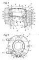
- FIGS. 1 to 3 a first embodiment of a device 11 according to the invention for beam guidance of a laser beam is shown.
- This device 11 is provided, for example, for the extraction of a laser beam in coaxial CO 2 lasers, which have a typical power range of, for example, 500 W to 2000 W.
- the device 11 according to FIG. 1 has a housing portion 12.
- stepped through holes 14 are provided to fix by means of screws the housing portion 12, for example, to the resonator.
- the housing section 12 may be arranged on a closure lid of a resonator of a coaxial CO 2 laser.
- the housing section 12 is integrated in a closure cover of a coaxial CO 2 laser.
- a flange surface 17 is provided, which is formed parallel to a support portion 18 for an optical element 19 with high precision.
- a circumferential collar 21 may be provided for additional guidance of the housing section 12 on a resonator or housing part of a resonator.
- This or the flange surface 17 surrounds a stepped bore 22 which, adjacent to the support section 18, has a cross-section which is preferably adapted to the beam profile.
- the adjacent thereto outlet opening 20 may be both round and rectangular and banana-shaped. Any additional geometry required for adaptation to the beam profile for beam guidance of a laser beam can also be introduced.
- the optical element 19 lies with its narrow edge region on the support section 18.
- a frame 23 preferably surrounds the optical element 19 completely and has a clearance fit to the optical element 19. During the beam guidance of the laser beam, heat is generated in the optical element 19 by the absorbed laser radiation. If necessary, expansions due to the heating allow a tension-free positioning due to the clearance fit.
- the frame 23 has an outer peripheral surface 26, through which the frame 23 is guided in a bore portion 27 of the housing portion 12.
- an undercut 30 adjoining the support section 18 is provided in the bore section 27.
- the frame 23, which also has the function of an intermediate body or adapter for adaptation to different body shapes of the optical elements 19, is disc-shaped and has a recess 28 which is larger than an opening 25 for the optical element 19.
- the recess 28 is formed such that around the opening 25 of the frame 23, a web-shaped bearing surface 33 is formed, on which after insertion of the optical element 19 a further seal 29 comes to rest. This seal 29 covers the gap between the optical element 19 and the web-shaped bearing surface 33 of the frame 23 in order to allow a seal in the beam direction.
- a holding element 31 defines the seal 29 to the optical element 19 and the web-shaped support surface 33 of the frame 23.
- an inner surface 32 of the holding element 31 is flush with respect to a circumferential surface 34 of the outlet opening 20 of the stepped bore 22 or that springs back against it.
- the size of the seal 29 is formed. It is thereby achieved that the free area formed by the circumferential surface 34 for beam guidance of the laser beam is not reduced by the seal 29 and the holding element 31 positioned at the beam exit side.
- the holding element 31 is fixed via a clamping element 36.
- the clamping element 36 is advantageously designed as a clamping ring and engages via an external thread 37 at a mounting portion 38 of the housing portion 12. As a result, a central introduction of force on the retaining element 31 is made possible.
- the external thread 37 may also be formed as a fine thread, so that a tightening torque of the clamping element 36 can be adjusted very sensitively preferably via a torque wrench.
- other clamping elements can be introduced, which fulfill the function that a finely dosed delivery of the holding force is made possible on the holding element 31 to fix the optical element 19 to the support section 18 bracing and tilting.
- the friction surfaces between the retaining element 31 and the clamping element 36 are as small as possible in diameter, so that the resulting friction torque when tightening the clamping element 36 is small.
- a positioning pin between the housing portion 12 and the frame 23 is provided for fixing the frame 23 in the correct position.
- the holding element 31 may preferably have as tightening a stop surface 41, which comes at an excessive torque on an end face 42 of the frame 23 to the plant. As a result, a crushing of the seal 29 and possibly damage to the optical element 19 can be omitted.
- the stop surface 41 is provided protruding on the end face 42 of the frame 23.
- the housing section 12 is preferably formed from a material with high thermal conductivity. For example, aluminum alloys or the like are used. These also have the advantage that both a cost-effective and precise machining is given.
- the support section 18 is manufactured with high precision by turning or milling with diamond, polycrystalline diamond (PCD), ceramics as well as grinding, precision turning or lapping. At the same time, this support section 18 has a high degree of flatness in order to allow a full-surface contact of the edge section of the optical element 19. As a result, a good heat dissipation can be achieved.
- a cooling channel 43 is provided near the support section 18, which preferably completely surrounds the outlet opening 20 near the support section 18.
- FIG. 2 For example, the design of such a cooling channel 43 in the plan view of the housing portion 12 is shown.
- the cooling channel 43 surrounding the optical element 19 has connecting pieces 44 for supplying and discharging a coolant liquid medium.
- the cooling channel 43 is produced, for example, by bores which are introduced into the housing section 12 such that they open into one another. By plug 46, bore portions 47, which are required for the production of the cooling channel sections, medium sealed, so that a circumferential cooling channel 43 is formed.
- the optical element 19 is advantageously formed of diamond when using this device in a coaxial CO 2 laser.
- This material has the advantage of high thermal conductivity. About that In addition, diamond has a small thermal expansion coefficient, whereby the thermal expansions are low.
- the optical elements 19 formed of diamond have the advantage that the geometry is retained on absorption of the laser radiation and heating in the optical element. A change in the form of a thermal lens or the like is not given. As a result, a deflection-free exit of the laser beam can be given.
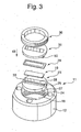
- FIG. 3 is an exploded view of the device according to the invention FIGS. 1 and 2 shown.
- FIGS. 1 and 2 By successively inserting the parts in the illustrated sequence in the direction of arrow 49, a fast and secure mounting of an optical element 19 in the housing section 12 can take place. It can also be seen from this that a certain orientation of the parts and positionally correct positioning result on their own due to the geometries. It also becomes clear from this illustration that the housing section 12 can also be part of a closure element or cover of a resonator.
- the individual components such as the optical element 19, the frame 23, the seals 24 and 29, the retaining element 31 and the clamping element 36 can be used independently of the further coupling of the housing section 12.
- the optical element 19 can be positioned in its final position to the support portion 18 of the housing portion 12.
- the subsequent insertion of the seal 29, the placement of the retaining element 31 and the tightening of the clamping element 36 allows a fixation of the optical element 19 without Twisting or tilting, so that a complete abutment of the edge region of the optical element 19 is given on the support portion 18 without damaging these surfaces.
- FIG. 4 is an alternative embodiment to FIG. 1 shown.
- the basic structure and the assembly sequence, as in FIG. 3 is shown are retained.
- the frame 23 surrounds an outer periphery 56 of the housing section 12 with a circumferential shoulder 51.
- the clamping element 36 engages around the shoulder 51 of the frame 23 in order to engage the fastening section 38 of the housing section 12 by means of a screw connection.
- a stop surface 41 is provided, which in turn serves as a tightening for the clamping element 36.
- FIG. 4 illustrated embodiment shows in contrast to that in the FIGS. 1 to 3 illustrated embodiment that instead of an installation of the components in a housing portion 12 and a fixation of the components is made possible by at least partially encompassing the housing portion 12.
Landscapes
- Physics & Mathematics (AREA)
- Engineering & Computer Science (AREA)
- Optics & Photonics (AREA)
- Plasma & Fusion (AREA)
- Mechanical Engineering (AREA)
- General Physics & Mathematics (AREA)
- Lasers (AREA)
- Laser Surgery Devices (AREA)
- Optical Couplings Of Light Guides (AREA)
Description
- Die Erfindung betrifft eine Vorrichtung zur Strahlführung eines Laserstrahls mit zumindest einem optischen Element gemäß dem Oberbegriff des Anspruchs 1.
- Die Lasertechnologie wird in den verschiedensten Fachgebieten eingesetzt. Beispielsweise werden für die flexible Materialbearbeitung CO2-Laser eingesetzt, z.B. quadratisch gefaltete oder koaxiale CO2-Laser.
- Zur Erhöhung der Leistung sind quadratisch gefaltete Resonatoren entwickelt worden, bei denen aufgrund der Faltung des Lichtweges eine lange Entladungsstrecke trotz kompakter Bauweise gegeben ist. Am Ende der Entladungsstrecken sind optische Elemente zur Strahlführung vorgesehen, welche an Gehäuseabschnitten positioniert sind.
- Bei den koaxialen CO2-Lasern handelt es sich um instabile Resonatoren mit ringförmigem Entladungsraum, welche beispielsweise zur Strahlführung torusförmig ausgebildete optische Elemente aufweisen.
- Die zur Strahlführung eingesetzten optischen Elemente sind in Abhängigkeit ihrer Funktion in ihrem Transmissions- und Reflexionsgrad unterschiedlich ausgebildet und angepasst. Es kommen optische Elemente zum Einsatz, die eine Totalreflexion ermöglichen als auch optische Elemente, die eine Teiltransmission mit unterschiedlichen Durchlässigkeitsgraden ermöglichen.
- Bei den quadratisch gefalteten CO2-Lasern wurde bislang eine Vorrichtung zur Aufnahme des optischen Elementes eingesetzt, welche einen ersten Ringkörper zur Auflage des optischen Elementes aufweist, der vakuumseitig zur Laserstrecke angeordnet ist. Über einen Zwischenkörper, der in radialer Richtung das optische Element umgibt, wird das optische Element zum Ringkörper positioniert. Auf den Zwischenkörper wird im Anschluss daran ein Haltekörper aufgesetzt, der das optische Element axial zu dem ersten Ringkörper fixiert. Durch Schraubverbindungen wird zunächst der Zwischenkörper zu dem Ringkörper fixiert. Im Anschluss daran wird der Haltekörper durch Spannschrauben, welche den Zwischenkörper durchdringen, zum Ringkörper ebenfalls fixiert. Diese Anordnung ist in der Montage des optischen Elementes sehr zeitaufwendig und erfordert eine hohe Präzision bei der Herstellung der Bauteilkomponenten. Durch das Fixieren des Haltekörpers zum Ringkörper über Spannschrauben kann zum einen aufgrund eines unterschiedlichen Anzugsmomentes der Spannschrauben eine nicht gleichmäßige Krafteinleitung auf das optische Element gegeben sein, wodurch Verspannungen im optischen Element auftreten. Gleichzeitig führen die Verspannungen der Verschraubung zur Unebenheit der Anlagefläche des optischen Elementes, wodurch eine geringere Wärmeleitung von dem optischen Element in den Ringkörper gegeben ist. Aus der Unebenheit der Anlagefläche folgt eine Deformation des optischen Elementes. Durch die kleinere Kontaktfläche gegenüber einer ideal planen Anlagefläche kann die Wärme schlechter aus dem optischen Element abgeführt werden und die Strahlqualität verschlechtert sich.
- Bei den koaxialen CO2-Lasern mit ihren instabilen Laserresonatoren wird die Laserstrahlung über eine Aussparung in einem Ringspiegel ausgekoppelt. Der Laserstrahl verlässt die Vakuumkammer durch ein transmittives, optisches Element, das den Abschluss der Vakuumkammer bildet. Erfolgt die Abdichtung des optischen Elementes z.B. durch Löten, ist die gelötete Verbindungsstelle beim Betrieb des Lasers einer Temperaturwechselbeanspruchung ausgesetzt. Dies hat zur Folge, dass die Verbindungsstelle im Laufe der Zeit undicht werden kann.
- Aus der
JP 60-189 276 Figur 4 ein mehrteiliges Gehäuse hervor, durch das ein optisches Element von einer Haltevorrichtung aufgenommen ist. Diese Haltevorrichtung umfasst an einem Gehäuseabschnitt einen Auflageabschnitt, an dem das optische Element anliegt. Zwischen dem Auflageabschnitt und dem optischen Element ist ein O-Ring zur Abdichtung vorgesehen, der auch zur Wärmeübertragung beiträgt. Dem Gehäuseabschnitt gegenüberliegend ist ein Halteelement vorgesehen, das über einen Dichtungsring das optische Element zum Auflageabschnitt positioniert. Am Halteelement greift ein Spannelement an, das über einen an dem Gehäuseabschnitt lösbar befestigten Gewindering mit dem Gehäuseabschnitt verbunden ist. Dieses mehrteilige Gehäuse weist den Nachteil auf, dass durch die mehrteilige Haltevorrichtung eine verspannungsfreie und einfache Montage nicht ermöglicht ist. Analoges gilt für dieJP 52-156642 - Der Erfindung liegt nunmehr die Aufgabe zugrunde, eine Vorrichtung zur Strahlführung eines Laserstrahls mit zumindest einem optischen Element zu schaffen, welches abweichend von einem runden Durchmesser eine Außenkontur aufweist, die eine gute Wärmeableitung aus dem optischen Element sowie eine einfache und schnelle als auch spannungsfreie Montage des optischen Elementes ermöglicht und die erforderliche Dichtheit aufweist.
- Diese Aufgabe wird durch die Merkmale des Anspruchs 1 gelöst.
- Durch eine gleichmäßig verteilte Krafteinleitung einer Haltekraft mit einem an dem Gehäuseabschnitt angreifenden Spannelement, durch welches ein Halteelement an dem optischen Element angreift und zur Anlage an einem Auflageabschnitt des Gehäuseabschnittes kommt, ist eine verspannungsfreie Anordnung des optischen Elements abweichend von einem runden Außendurchmesser zum Auflageabschnitt an dem Gehäuseabschnitt gegeben, welches eine Außenkontur aufweist. Des weiteren ist dadurch ermöglicht, dass jede beliebige Geometrie eines optischen Elements einsetzbar ist. Dadurch kann eine spezifische Anpassung der Vorrichtung an unterschiedliche Strahlprofile ermöglicht sein. Insbesondere bei der Ausgestaltung des optischen Elementes abwelchend von einem runden Durchmesser in der Außenkontur ist vorgesehen, dass das optische Element durch einen Rahmen in einer Position deckungsgleich zur Austrittsöffnung im Gehäuseabschnitt fixiert ist. Dadurch kann das optische Element die Austrittsöffnung vollständig abdecken.
- Diese Anpassung der optischen Elemente an das Strahlprofil weist den Vorteil auf, dass ein schnelles Abführen der in dem optischen Element durch die absorbierte Laserstrahlung entstehende Wärme ermöglicht ist. Darüber hinaus wird die Wärmeableitung durch die Anlage an dem Auflageabschnitt begünstigt, der die Öffnung des Gehäuseabschnitts umgibt. Dadurch können Deformationen des optischen Elements gering gehalten oder auch unterbunden sein, wodurch auch die Dichtheit erhöht ist.
- Des weiteren weist die Dichtung oder ein dichtendes Dämpfungselement zwischen dem Halteelement und dem optischen Element den Vorteil auf, dass durch die unterschiedliche Wärmeausdehnung des optischen Elements und des Gehäuseabschnitts eine dichte Anordnung zwischen dem optischen Element und einem das optische Element umgebenden Gehäuseabschnitt oder einem das optische Element umgebenden Abschnitt des Halteelements gegeben ist. Gleichzeitig kann durch die Federwirkung der Dichtung ein hinreichender Anpressdruck des optischen Elements zum Auflageabschnitt des Gehäuseabschnitts aufrechterhalten bleiben, um eine gute Wärmeableitung sicherzustellen.
- Darüber hinaus kann das optische Element durch die gleichmäßig verteilte Krafteinleitung vollständig an dem Auflageabschnitt anliegen und die Ebenheit der Anlagefläche erhalten bleiben, wodurch eine gute Wärmeableitung gegeben ist. Durch die gleichmäßig verteilte Krafteinleitung der Haltekraft mit einem Spannelement wird des weiteren ermöglicht, dass eine einfache Montage des optischen Elementes zum Gehäuseabschnitt gegeben ist. Das zumindest eine optische Element des zumindest einen Halteelements und das Spannelement können einfach und sicher nacheinander zum Gehäuseabschnitt montiert werden. Da das Spannelement die Wirkung eines Zentralverschlusses aufweist, kann des weiteren eine erhebliche Einsparung der Montagezeit erzielt werden. Durch die Anordnung eines Befestigungselementes an dem Gehäuseabschnitt für das Spannelement ist des weiteren eine Bauteilereduzierung gegeben, wodurch eine Verringerung der Herstellungskosten erzielt wird.
- Nach einer vorteilhaften Ausgestaltung der Erfindung ist vorgesehen, dass das Spannelement als Schraubring ausgebildet ist. Dadurch ist ein in der Montage leicht zu handhabendes Spannelement gegeben. Der Einsatz des Schraubringes als Spannelement ermöglicht eine über die Umfangsfläche des Schraubringes gleichmäßig verteilte Krafteinleitung auf ein Halteelement, wodurch das optische Element mit einer gleichmäßigen Anpresskraft auf dem Auflageabschnitt des Gehäuseabschnittes anliegt.
- Nach einer weiteren vorteilhaften Ausgestaltung der Erfindung ist vorgesehen, dass zwischen dem Halteelement und dem Spannelement eine Spannfläche vorgesehen ist, die zumindest eine abschnittsweise Ringfläche aufweist. Diese Ausgestaltung ermöglicht ein zwischen dem Spannelement und Haltering verringertes Reibmoment, so dass eine Übertragung der Axialkraft ohne zumindest teilweiser Rotation des Halteelements ermöglicht ist, wodurch das optische Element ohne Veränderung seiner vorfixierten Lage zum Auflageabschnitt gedrückt wird.
- Nach einer weiteren vorteilhaften Ausgestaltung der Erfindung ist vorgesehen, dass das Halteelement eine Anschlagfläche als Anziehsicherung aufweist. Dadurch kann bei Überschreitung eines maximalen Drehmomentes für das Anziehen des Spannelementes eine sichere Montage des optischen Elements ohne Beschädigung gegeben sein. Da das Halteelement über eine Dichtung oder ein dichtendes Dämpfungselement an dem optischen Element anliegt, ist auch eine verspannungsfreie Positionierung des optischen Elements zum Auflageabschnitt gegeben. Alternativ kann auch vorgesehen sein, dass die Anschlagfläche an einem Gehäuseabschnitt oder weiteren Bauteil angeordnet ist.
- Nach einer weiteren vorteilhaften Ausgestaltung der Erfindung ist vorgesehen, dass der Auflageabschnitt des Gehäuses durch Drehen oder Fräsen mit Diamant, Polykristallindiamant (PKD), Keramiken als auch Schleifen, Präzisionsdrehen oder Läppen hergestellt ist. Durch die damit erzielte geringe Rauhigkeit weist der Auflageabschnitt eine höhere Kontaktfläche zwischen dem optischen Element und dem Auflageabschnitt auf, die zu einer verbesserten Wärmeableitung führt. Des weiteren kann durch diese Bearbeitung ein hohes Maß an Ebenheit, beispielsweise weniger als 10 µm, vorzugsweise weniger als 1 µm, erzielt werden, wodurch die Verlustleistung, welche sich in einer Erwärmung des optischen Elements niederschlägt, verringert wird.
- Eine vorteilhafte Ausgestaltung der Erfindung sieht vor, dass das optische Element aus Diamant, Zinkselenid, Galliumarsenid, Silicium oder Kupfer ausgebildet ist. In Abhängigkeit des Verwendungszweckes der Vorrichtung, dem Lasertyp und der Leistung des Lasers kann der Werkstoff für das optische Element ausgewählt sein. Beispielsweise wird Silizium bei einem quadratisch gefalteten CO2-Lasers als Umlenkspiegel bis zu 4 kW eingesetzt und Kupfer für einen höheren Leistungsbereich. Zinkselenid wird bevorzugt als Auskoppelspiegel in einem quadratisch gefalteten CO2-Laser eingesetzt. Bei koaxialen CO2-Lasern kann bei geringen Leistungen Zinkselenid oder über alle Leistungsbereiche Diamant als Werkstoff für das optische Element eingesetzt werden.
- Nach einer vorteilhaften Ausführungsform der Erfindung ist vorgesehen, dass ein auf dem Auflageabschnitt anliegender Bereich des optischen Elementes in alle Richtungen betragsmäßig gleich ist. Dadurch kann eine gleichmäßige Wärmeableitung gegeben sein.
- Nach einer weiteren vorteilhaften Ausgestaltung der Erfindung ist vorgesehen, dass zwischen dem Gehäuseabschnitt und dem Rahmen als auch zwischen dem optischen Element und dem Rahmen jeweils eine Dichtung vorgesehen ist. Dadurch kann in einfacher Weise eine vakuumdichte Anordnung geschaffen werden. Durch die getrennte Ausgestaltung kann eine Vereinfachung in der Montage gegeben sein. Zusätzlich kann eine Erhöhung der Dichtigkeit ermöglicht werden.
- Nach einer weiteren vorteilhaften Ausgestaltung der Erfindung ist vorgesehen, dass das optische Element eine an das Strahlproril angepasste Außenkontur aufweist, die vorzugsweise rechteckförmig, bananenförmig oder dergleichen und insbesondere aus Diamant hergestellt ist. Insbesondere beim Einsatz zur Auskopplung eines Laserstrahle aus einem koaxialen CO2-Laser ist diese Ausführungsform vorteilhaft. Durch die Anpassung der Geometrie des optischen Elementes an das ausgekoppelte Strahlprofil können die Herstellungskosten des optischen Elementes, insbesondere bei der Verwendung von Diamant reduziert werden. Gleichzeltig kann die durch die absorbierte Laserstrahlung entstehende Wärme unmittelbar über die Anlagefläche in den Gehäuseabschnitt abgeführt werden. Darüber hinaus kann durch die Einbringung einer zentralen Haltekraft über das Spannelement und die Trennung der Kraftübertragung auf ein Halteelement auch bei nicht runden Geometrien der optischen Elemente eine gute Dichtigkeit erzielt werden.
- Vorzugsweise werden Industriediamanten eingesetzt. Aufgrund der hohen Wärmeleitfähigkeit von Diamant kann die Wärme, die durch die absorbierte Laserstrahlung im optischen Element entsteht, sehr schnelle in den gekühlten Gehäuseabschnitt abgeführt werden. Darüber hinaus ist eine geringe Wärmeausdehnung und eine hohe mechanische Festigkeit gegeben. Dadurch kann das optische Element seine Ausgangsform im wesentlichen beibehalten. Des weiteren weist Diamant eine hohe Lebensdauer auch bei höheren Leistungen auf. Bei instabilen Resonatoren, wie dies beispielsweise bei koaxialen CO2-Lasern der Fall ist, wird der Laserstrahl nach dem Austritt aus der Vakuumkammer durch Spiegel und durch eine Blende geformt. Hierbei muss der Fokus des Laserstrahls in der Blende liegen. Durch übermäßige Erwärmung des optischen Elementes und einer daraus resultierenden Deformation wäre eine Ablenkung des austretenden Laserstrahls bzw. eine Fokusverschiebung in Strahlrichtung gegeben. Dies könnte zur Beschädigung der Blende im Strahlteleskop führen und kann durch die vorteilhafte Ausgestaltung unterbunden sein.
- Anhand der nachfolgenden Zeichnungen und der Beschreibung werden bevorzugte Ausführungsbeispiele der Erfindung näher beschrieben. Es zeigen:
- Figur 1
- eine schematische Darstellung im Querschnitt einer erfindungsgemäßen Vorrichtung,
- Figur 2
- eine schematische Draufsicht der Vorrichtung gemäß
Figur 1 , - Figur 3
- eine Explosionsdarstellung der Vorrichtung gemäß
Figur 1 , in der die Einbaureihenfolge der Bauteile dargestellt ist und - Figur 4
- eine schematische Darstellung im Querschnitt einer alternativen Vorrichtung zu
Figur 1 . - In den
Figuren 1 bis 3 ist eine erste Ausführungsform einer erfindungsgemäßen Vorrichtung 11 zur Strahlführung eines Laserstrahls dargestellt. Diese Vorrichtung 11 ist beispielsweise für die Auskopplung eines Laserstrahls bei koaxialen CO2-Lasern vorgesehen, welche einen typischen Leistungsbereich von beispielsweise 500 W bis 2000 W aufweisen. - Die Vorrichtung 11 gemäß
Figur 1 weist einen Gehäuseabschnitt 12 auf. Im äußeren Bereich des Gehäuseabschnitts 12 sind gestufte Durchgangsbohrungen 14 vorgesehen, um mittels Schrauben den Gehäuseabschnitt 12 beispielsweise zum Resonator zu fixieren. Beispielsweise kann der Gehäuseabschnitt 12 an einem Verschlussdeckel eines Resonators eines koaxialen CO2-Lasers angeordnet sein. Alternativ kann auch vorgesehen sein, dass der Gehäuseabschnitt 12 in einem Verschlussdeckel eines koaxialen CO2-Lasers integriert ist. - Zur Montage der Vorrichtung 11 an einem Resonator ist eine Anflanschfläche 17 vorgesehen, welche parallel zu einem Auflageabschnitt 18 für ein optisches Element 19 mit einer hohen Präzision ausgebildet ist. Zur zusätzlichen Führung des Gehäuseabschnitts 12 an einem Resonator oder Gehäuseteil eines Resonators kann ein umlaufender Bund 21 vorgesehen sein. Dieser oder die Anflanschfläche 17 umgibt eine Stufenbohrung 22, welche an den Auflageabschnitt 18 angrenzend einen an das Strahlprofil vorzugsweise angepassten Querschnitt aufweist. Die daran angrenzende Austrittsöffnung 20 kann sowohl rund als auch rechteckig als auch bananenförmig ausgebildet sein. Jede weitere Geometrie, welche für die Anpassung an das Strahlprofil zur Strahlführung eines Laserstrahis erforderlich ist, kann ebenfalls eingebracht werden.
- Das optische Element 19 liegt mit seinem schmalen Randbereich auf dem Auflageabschnitt 18 auf. Ein Rahmen 23 umgibt das optische Element 19 vorzugsweise vollständig und weist zum optischen Element 19 eine Spielpassung auf. Während der Strahlführung des Laserstrahls entsteht Wärme in dem optischen Element 19 durch die absorbierte Laserstrahlung. Gegebenenfalls auftretende Ausdehnungen aufgrund der Erwärmung ermöglichen durch die Spielpassung eine verspannungsfreie Positionierung.
- Zwischen dem Rahmen 23 und dem Auflageabschnitt 18 ist eine Dichtung 24 vorgesehen, um die Austrittsöffnung 20 der Stufenbohrung 22 vakuumdicht abzuschließen. Der Rahmen 23 weist eine äußere Umfangsfläche 26 auf, durch welche der Rahmen 23 in einem Bohrungsabschnitt 27 des Gehäuseabschnitts 12 geführt ist. Zur vollständigen Anlage an den Auflageabschnitt 18 ist in dem Bohrungsabschnitt 27 eine an den Auflageabschnitt 18 angrenzende Hinterschneidung 30 vorgesehen. Der Rahmen 23, der auch die Funktion eines Zwischenkörpers oder Adapters zur Anpassung an unterschiedliche Körperformen der optischen Elemente 19 aufweist, ist scheibenförmig ausgebildet und weist eine Ausnehmung 28 auf, welche größer als eine Öffnung 25 für das optische Element 19 ist. Die Ausnehmung 28 ist derart ausgebildet, dass um die Öffnung 25 des Rahmens 23 eine stegförmige Auflagefläche 33 ausgebildet ist, auf welche nach dem Einbringen des optischen Elements 19 eine weitere Dichtung 29 zur Anlage kommt. Diese Dichtung 29 überdeckt den Spalt zwischen dem optischen Element 19 und der stegförmigen Auflagefläche 33 des Rahmens 23, um in Strahlrichtung eine Abdichtung zu ermöglichen.
- Ein Halteelement 31 legt die Dichtung 29 zum optischen Element 19 und der stegförmigen Auflagefläche 33 des Rahmens 23 fest. Dabei ist vorzugsweise vorgesehen, dass eine innere Fläche 32 des Halteelementes 31 gegenüber einer Umfangsfläche 34 der Austrittsöffnung 20 der Stufenbohrung 22 bündig ist oder dieser gegenüber zurückspringt. Ebenso ist die Größe der Dichtung 29 ausgebildet. Dadurch wird erzielt, dass der durch die Umfangsfläche 34 gebildete freie Bereich zur Strahlführung des Laserstrahles durch die strahlaustrittsseitig positionierte Dichtung 29 und das Halteelement 31 nicht verkleinert wird.
- Das Halteelement 31 wird über ein Spannelement 36 fixiert. Das Spannelement 36 ist vorteilhafterweise als Spannring ausgebildet und greift über ein Außengewinde 37 an einem Befestigungsabschnitt 38 des Gehäuseabschnitts 12 an. Dadurch ist eine zentrale Krafteinleitung auf das Halteelement 31 ermöglicht. Das Außengewinde 37 kann auch als Feingewinde ausgebildet sein, so dass ein Anzugsmoment des Spannelementes 36 vorzugsweise über einen Drehmomentenschlüssel sehr feinfühlig eingestellt werden kann. Alternativ zu diesem Spannelement 36 können auch weitere Spannelemente eingebracht werden, welche die Funktion erfüllen, dass eine feindosierte Zustellung der Haltekraft auf das Halteelement 31 ermöglicht wird, um das optische Element 19 zum Auflageabschnitt 18 verspannungs- und verkippungsfrei zu fixieren.
- Vorteilhafterweise ist vorgesehen, dass die Reibflächen zwischen dem Halteelement 31 und dem Spannelement 36 im Durchmesser möglichst klein sind, damit das entstehende Reibmoment beim Anziehen des Spannelementes 36 klein ist. Um eine genaue Ausrichtung des optischen Elementes 19 zur Austrittsöffnung 20 zu ermöglichen und ein Verdrehen zu verhindern, kann zusätzlich vorgesehen sein, dass zur lagerichtigen Fixierung des Rahmens 23 ein Positionierstift zwischen dem Gehäuseabschnitt 12 und dem Rahmen 23 vorgesehen ist. Das Halteelement 31 kann vorzugsweise als Anziehsicherung eine Anschlagfläche 41 aufweisen, welche bei einem überhöhten Anzugsmoment auf einer Stirnfläche 42 des Rahmens 23 zur Anlage kommt. Dadurch können eine Quetschung der Dichtung 29 und gegebenenfalls Beschädigungen des optischen Elements 19 ausbleiben. Alternativ kann auch vorgesehen sein, dass die Anschlagfläche 41 hervorspringend an der Stirnfläche 42 des Rahmens 23 vorgesehen ist.
- Der Gehäuseabschnitt 12 ist bevorzugt aus einem Material mit hoher Wärmeleitfähigkeit ausgebildet. Beispielsweise werden Aluminiumlegierungen oder dergleichen eingesetzt. Diese weisen darüber hinaus den Vorteil auf, dass sowohl eine kostengünstige als auch präzise Bearbeitung gegeben ist. Der Auflageabschnitt 18 wird hochpräzise durch Drehen oder Fräsen mit Diamant, Polykristallindiamant (PKD), Keramiken als auch Schleifen, Präzisionsdrehen oder Läppen hergestellt. Gleichzeitig weist dieser Auflageabschnitt 18 ein hohes Maß an Ebenheit auf, um eine vollflächige Anlage des Randabschnittes des optischen Elementes 19 zu ermöglichen. Dadurch kann eine gute Wärmeableitung erzielt werden. Zusätzlich ist nahe dem Auflageabschnitt 18 ein Kühlkanal 43 vorgesehen, der vorzugsweise die Austrittsöffnung 20 nahe dem Auflageabschnitt 18 vollständig umgibt.
- In
Figur 2 ist beispielsweise die Ausgestaltung eines derartigen Kühlkanales 43 in der Draufsicht auf den Gehäuseabschnitt 12 dargestellt. Der das optische Element 19 umgebende Kühlkanal 43 weist Anschlussstutzen 44 zum Zuführen und Abführen eines Kühlflüssigkeitsmediums auf. Der Kühlkanal 43 wird beispielsweise durch Bohrungen hergestellt, die derart in den Gehäuseabschnitt 12 eingebracht werden, dass diese ineinander münden. Durch Verschlussstopfen 46 sind Bohrungsabschnitte 47, die zum Herstellen der Kühlkanalabschnitte erforderlich sind, mediumsdicht verschlossen, so dass ein umlaufender Kühlkanal 43 ausgebildet ist. - Das optische Element 19 ist beim Einsatz dieser Vorrichtung in einem koaxialen CO2-Laser vorteilhafterweise aus Diamant ausgebildet. Dieser Werkstoff weist den Vorteil einer hohen Wärmeleitfähigkeit auf. Darüber hinaus weist Diamant einen kleinen Wärmeausdehnungskoeffizienten auf, wodurch die Wärmeausdehnungen gering sind. Auf dem optischen Element 19 ist eine Beschichtung aufgebracht, deren Fläche nur geringfügig kleiner als die Austrittsöffnung 20 der Stufenbohrung 22 ausgebildet ist. Dadurch ist der Randbereich des optischen Elementes 19, der an dem Auflageabschnitt 18 anliegt, frei von der Beschichtung, wodurch eine hohe Wärmeableitung ermöglicht ist. Durch die Anpassung der Geometrie des optischen Elementes 19 an das Strahlprofil ist ermöglicht, dass die Kosten für die Herstellung eines optischen Elementes 19 aus Diamant reduziert werden. Des weiteren weisen die aus Diamant ausgebildeten optischen Elemente 19 den Vorteil auf, dass bei Absorption der Laserstrahlung und Erwärmung in dem optischen Element die Geometrie erhalten bleibt. Eine Veränderung in Form einer thermischen Linse oder dergleichen ist nicht gegeben. Dadurch kann ein ablenkungsfreier Austritt des Laserstrahles gegeben sein.
- In
Figur 3 ist eine Explosionsdarstellung der erfindungsgemäßen Vorrichtung gemäßFigur 1 und 2 dargestellt. Durch ein nacheinander Einsetzen der Teile in der dargestellten Reihenfolge in Pfeilrichtung 49 kann eine schnelle und sichere Montage eines optischen Elementes 19 in dem Gehäuseabschnitt 12 erfolgen. Daraus ist auch ersichtlich, dass eine bestimmte Ausrichtung der Teile und lagerichtige Positionlerung sich aufgrund der Geometrien von alleine ergibt. Auch wird aus dieser Darstellung deutlich, dass der Gehäuseabschnitt 12 auch ein Teil eines Verschlusselementes oder Deckels eines Resonators sein kann. Die einzelnen Komponenten wie das optische Element 19, der Rahmen 23, die Dichtungen 24 und 29, das Halteelement 31 als auch das Spannelement 36 können unabhängig der weiteren Ankopplung des Gehäuseabschnitts 12 eingesetzt werden. - Aufgrund der Einbaureihenfolge, wonach zunächst der Rahmen 23 in den Bohrungsabschnitt 27 eingesetzt wird, kann das optische Element 19 in seiner endgültigen Position zum Auflageabschnitt 18 des Gehäuseabschnitts 12 positioniert werden. Das nachfolgende Einlegen der Dichtung 29, dem Aufsetzen des Halteelementes 31 und das Anziehen des Spannelementes 36 ermöglicht eine Fixierung des optischen Elementes 19 ohne Verdrehung oder Verkippung, so dass eine vollständige Anlage des Randbereiches des optischen Elementes 19 auf dem Auflageabschnitt 18 ohne Beschädigung dieser Flächen gegeben ist.
- In
Figur 4 ist eine alternative Ausführungsform zuFigur 1 dargestellt. Der prinzipielle Aufbau und die Montagereihenfolge, wie dies inFigur 3 dargestellt ist, werden beibehalten. Abweichend zu der Ausführungsform inFigur 1 bis 3 ist bei dieser Ausführungsform gemäßFigur 4 vorgesehen, dass der Rahmen 23 mit einer umlaufenden Schulter 51 einen Außenumfang 56 des Gehäuseabschnitts 12 umgreift. In Analogie umgreift das Spannelement 36 die Schulter 51 des Rahmens 23, um durch eine Schraubverbindung am Befestigungsabschnitt 38 des Gehäuseabschnitts 12 anzugreifen. An einem auskragenden Ende 52 der Schulter 51 ist eine Anschlagfläche 41 vorgesehen, welche wiederum als Anziehsicherung für das Spannelement 36 dient. Diese inFigur 4 dargestellte Ausführungsform zeigt im Gegensatz zu der in denFiguren 1 bis 3 dargestellten Ausführungsform, dass anstelle eines Einbaus der Komponenten in einen Gehäuseabschnitt 12 auch eine Fixierung der Komponenten durch zumindest teilweise Umgreifen des Gehäuseabschnitts 12 ermöglicht ist. Im übrigen gelten die Ausführungen zu denFiguren 1 bis 3 .
Claims (11)
- Vorrichtung zur Strahlführung eines Laserstrahls mit zumindest einem optischen Element (19), welches mit einem Halteelement (31) zu einem Auflageabschnitt (18) positioniert ist und mit einem Spannelement (36), welches das optische Element (19) zum Auflageabschnitt (18) eines Gehäuseabschnitts (12) fixiert, wobei der den Auflageabschnitt (18) aufweisende Gehäuseabschnitt (12) einen an diesem Gehäuseabschnitt (12) angeordneten Befestigungsabschnitt (38) aufweist, an welchem das Spannelement (36) zur gleichmäßig verteilten Krafteinleitung einer Haltekraft angreift und das optische Element (19) unter Zwischenschaltung des zumindest einen Halteelements (31) zum Auflageabschnitt (18) positioniert und mit einer Dichtung (29), die zwischen dem optischen Element (19) und dem Halteelement (31) an einem Bereich des optischen Elements (19) vorgesehen ist, welcher einem auf dem Auflageabschnitt (18) aufliegenden Bereich des optischen Elements (19) gegenüberliegt, dadurch gekennzeichnet,- dass zwischen dem Halteelement (31) und dem Auflageabschnitt (18) des Gehäuseabschnitts (12) ein Rahmen (23) vorgesehen ist, der eine Öffnung (25) zur Aufnahme des optischen Elementes (19) umfasst, welches eine von einem runden Durchmesser abweichende Außenkontur Zur Aupussung der Geometrie des optischen Elementes art das ausgekoppelte strahlprofil des Laserstrals aufweist, wobei um die Öffnung (25) des Rahmens (23) eine stegförmige Anlagefläche (33) des Rahmens (23) ausgebildet ist und- dass das in der Öffnung (25) des Rahmen (23) eingesetzte optische Element (19) deckungsgleich zur Austrittsöffnung (20) im Gehäuseabschnitt (12) fixiert ist und an dem Auflageabschnitt (18) aufliegt und die Dichtung (29) einen Spalt zwischen dem optischen Element (19) und der stegförmigen Amlagefläche (33) des Rahmens (23) überdeckt.
- Vorrichtung nach Anspruch 1, dadurch gekennzeichnet, dass das Spannelement (36) als Schraubring ausgebildet ist.
- Vorrichtung nach Anspruch 1 oder 2, dadurch gekennzeichnet, dass zwischen dem Spannelement (36) und dem Halteelement (31) eine Spannfläche vorgesehen ist, die zumindest eine abschnittsweise Ringfläche aufweist.
- Vorrichtung nach einem der vorhergehenden Ansprüche, dadurch gekennzeichnet, dass das Halteelement (31) eine Anschlagfläche (41) als Anziehsicherung aufweist.
- Vorrichtung nach einem der vorhergehenden Ansprüche, dadurch gekennzeichnet, dass der Auflageabschnitt (18) durch Drehen oder Fräsen mit Diamant, Polykristallindiamant (PKD), Keramiken als auch Schleifen, Präzisionsdrehen oder Läppen bearbeitet ist.
- Vorrichtung nach einem der vorhergehenden Ansprüche, dadurch gekennzeichnet, dass der Auflageabschnitt (18) eine Ebenheit von weniger als 10 µm, vorzugsweise 1 µm, aufweist.
- Vorrichtung nach einem der vorhergehenden Ansprüche, dadurch gekennzeichnet, dass das optische Element aus Diamant, Zinkselenid, Galliumarsenid, Silizium oder Kupfer ausgebildet ist.
- Vorrichtung nach Anspruch 1, dadurch gekennzeichnet, dass der auf dem Auflageabschnitt (18) liegende Bereich des optischen Elementes (19) in alle Richtungen betragsmäßig gleich ist.
- Vorrichtung nach Anspruch 1, dadurch gekennzeichnet, dass das Halteelement (31) in eine Ausnehmung (28) des Rahmens (23) einsetzbar ist und das optische Element (19) und den Rahmen (23) zum Auflageabschnitt (18) fixiert.
- Vorrichtung nach Anspruch 1, dadurch gekennzeichnet, dass zwischen dem Gehäuseabschnitt (12) und dem Rahmen (23) jeweils eine Dichtung (24) vorgesehen ist.
- Vorrichtung nach Anspruch 1, dadurch gekennzeichnet, dass das optische Element (19) eine an ein Strahlprofil des Laserstrahls angepasste Außenkontur aufweist, die vorzugsweise rechteckförmig oder bananenförmig ausgebildet und insbesondere aus Diamant hergestellt ist.
Applications Claiming Priority (2)
| Application Number | Priority Date | Filing Date | Title |
|---|---|---|---|
| DE10151587 | 2001-10-23 | ||
| DE10151587A DE10151587A1 (de) | 2001-10-23 | 2001-10-23 | Vorrichtung zur Strahlführung eines Laserstrahls |
Publications (3)
| Publication Number | Publication Date |
|---|---|
| EP1306709A2 EP1306709A2 (de) | 2003-05-02 |
| EP1306709A3 EP1306709A3 (de) | 2004-06-23 |
| EP1306709B1 true EP1306709B1 (de) | 2008-08-20 |
Family
ID=7703011
Family Applications (1)
| Application Number | Title | Priority Date | Filing Date |
|---|---|---|---|
| EP02023280A Expired - Lifetime EP1306709B1 (de) | 2001-10-23 | 2002-10-17 | Vorrichtung zur Strahlführung eines Laserstrahls |
Country Status (4)
| Country | Link |
|---|---|
| US (1) | US6700714B2 (de) |
| EP (1) | EP1306709B1 (de) |
| AT (1) | ATE405858T1 (de) |
| DE (2) | DE10151587A1 (de) |
Families Citing this family (14)
| Publication number | Priority date | Publication date | Assignee | Title |
|---|---|---|---|---|
| US7183548B1 (en) * | 2004-02-25 | 2007-02-27 | Metadigm Llc | Apparatus for modifying and measuring diamond and other workpiece surfaces with nanoscale precision |
| US7049544B2 (en) * | 2004-03-26 | 2006-05-23 | Ultratech, Inc. | Beamsplitter for high-power radiation |
| EP1643281A1 (de) * | 2004-10-02 | 2006-04-05 | Trumpf Werkzeugmaschinen GmbH + Co. KG | Optisches Element einer Laserbearbeitungsmaschine und Halterung des optischen Elements |
| EP1649967B1 (de) | 2004-10-20 | 2011-08-10 | TRUMPF Werkzeugmaschinen GmbH + Co. KG | Optisches Element eines Laserbearbeitungskopfs |
| DE102006046435B4 (de) * | 2006-09-22 | 2008-08-14 | Dreier Lasermesstechnik Gmbh | Messkugel-Reflektor |
| DE102006055738B4 (de) * | 2006-11-25 | 2010-10-07 | Trumpf Laser- Und Systemtechnik Gmbh | Vorrichtung zum Verändern des Strahldurchmessers eines durch ein optisches Element hindurchgehenden Laserstrahls mittels Temperaturänderung |
| JP5748205B2 (ja) | 2010-08-27 | 2015-07-15 | ギガフォトン株式会社 | ウィンドウユニット、ウィンドウ装置、レーザ装置及び極端紫外光生成装置 |
| JP5868670B2 (ja) * | 2011-11-28 | 2016-02-24 | ギガフォトン株式会社 | ホルダ装置、チャンバ装置、および、極端紫外光生成装置 |
| JP5964383B2 (ja) | 2014-10-16 | 2016-08-03 | ファナック株式会社 | 弾性シール部材の取付治具 |
| GB201701173D0 (en) * | 2017-01-24 | 2017-03-08 | Element Six Tech Ltd | Synthetic diamond plates |
| DE102017209696A1 (de) * | 2017-06-08 | 2018-12-13 | Trumpf Laser Gmbh | Schutzglas mit Transponder und Einbauhilfe sowie zugehöriges Laserwerkzeug |
| DE102018115694A1 (de) * | 2018-06-28 | 2020-01-02 | Faurecia Emissions Control Technologies, Germany Gmbh | Fügevorrichtung |
| JP7291587B2 (ja) * | 2019-09-24 | 2023-06-15 | 三菱重工業株式会社 | レーザ加工ヘッドおよびレーザ加工装置 |
| CA3175132A1 (en) * | 2020-03-11 | 2021-09-16 | Arvind Sukumaran | External filter holder arrangement in operative microscopes for fluorescence guided surgery |
Family Cites Families (19)
| Publication number | Priority date | Publication date | Assignee | Title |
|---|---|---|---|---|
| DE2002361B2 (de) * | 1970-01-20 | 1975-05-07 | Balda-Werke Photographische Geraete Und Kunststoff Gmbh & Co Kg, 4980 Buende | Verfahren zur Herstellung eines Kamera-Suchergehäuses aus Kunststoff und Vorrichtung zur Durchführung des Verfahrens |
| JPS52156642A (en) * | 1976-06-21 | 1977-12-27 | Nec Corp | Laser mirror supporting device |
| DE3330626A1 (de) * | 1983-08-25 | 1987-06-25 | Wisotzki Juergen | Spiegel fuer die lasertechnik |
| JPS60189276A (ja) * | 1984-03-08 | 1985-09-26 | Sumitomo Electric Ind Ltd | レ−ザ共振器における反射鏡の冷却方法 |
| US4680771A (en) * | 1985-12-31 | 1987-07-14 | Amada Engineering Service Co., Inc. | Mirror adjustment device in laser oscillator |
| JPH0746736B2 (ja) * | 1986-10-09 | 1995-05-17 | 株式会社東芝 | 気体レーザ装置 |
| US4777639A (en) * | 1986-12-15 | 1988-10-11 | Prc Corporation | Laser optical element mounting arrangement and method |
| JPH0770767B2 (ja) * | 1987-03-19 | 1995-07-31 | 株式会社東芝 | レ−ザ用ミラ−保持機構 |
| DE4016579C2 (de) * | 1990-05-23 | 1994-12-15 | Fraunhofer Ges Forschung | Laser mit Schwingspiegel zur Leistungsmodulation |
| US5249082A (en) * | 1991-05-08 | 1993-09-28 | Eastman Kodak Company | Exact constraint arrangement for and methods of mounting an element such as a lens |
| DE9209561U1 (de) * | 1992-07-16 | 1992-11-05 | Weidmüller Interface GmbH & Co, 4930 Detmold | Fokussierungseinrichtung, insbesondere für einen Laser-Werkzeugkopf |
| US5392308A (en) * | 1993-01-07 | 1995-02-21 | Sdl, Inc. | Semiconductor laser with integral spatial mode filter |
| US5424872A (en) * | 1994-04-08 | 1995-06-13 | Recon/Optical, Inc. | Retrofit line of sight stabilization apparatus and method |
| JP2983148B2 (ja) * | 1994-12-02 | 1999-11-29 | 日本軽金属株式会社 | レーザ加工装置 |
| IT1277080B1 (it) * | 1995-12-14 | 1997-11-04 | Salvagnini Italia Spa | Testa di focalizzazione di un fascio laser dotata di una lente di focalizzazione per una macchina di lavorazione di pezzi metallici |
| GB2313472B (en) * | 1996-05-22 | 2000-10-18 | Avimo Ltd | Laser resonators |
| DE19628875C2 (de) * | 1996-07-17 | 2002-02-14 | Bayerische Motoren Werke Ag | Anordnung zum Herauslösen von PUR-Schaumkern aus Kraftfahrzeugsitzen |
| US5881088A (en) * | 1997-01-08 | 1999-03-09 | Trw Inc. | Face-cooled high-power laser optic cell |
| WO1999013370A1 (de) * | 1997-09-05 | 1999-03-18 | Leica Microsystems Ag | Mikroskop, insbesondere fluoreszenzmikroskop, insbesondere stereo-fluoreszenzmikroskop |
-
2001
- 2001-10-23 DE DE10151587A patent/DE10151587A1/de not_active Ceased
-
2002
- 2002-10-17 AT AT02023280T patent/ATE405858T1/de not_active IP Right Cessation
- 2002-10-17 EP EP02023280A patent/EP1306709B1/de not_active Expired - Lifetime
- 2002-10-17 DE DE50212665T patent/DE50212665D1/de not_active Expired - Lifetime
- 2002-10-23 US US10/280,583 patent/US6700714B2/en not_active Expired - Lifetime
Also Published As
| Publication number | Publication date |
|---|---|
| EP1306709A3 (de) | 2004-06-23 |
| DE10151587A1 (de) | 2003-05-22 |
| US20030123160A1 (en) | 2003-07-03 |
| ATE405858T1 (de) | 2008-09-15 |
| DE50212665D1 (de) | 2008-10-02 |
| US6700714B2 (en) | 2004-03-02 |
| EP1306709A2 (de) | 2003-05-02 |
Similar Documents
| Publication | Publication Date | Title |
|---|---|---|
| EP1306709B1 (de) | Vorrichtung zur Strahlführung eines Laserstrahls | |
| DE3541744C2 (de) | ||
| DE4433888C2 (de) | Festkörperlaser mit Kühleinrichtung | |
| EP1205013B1 (de) | Festkörperlaserkühlung | |
| EP1500173B1 (de) | Laserstrahlquelle mit einem eine dünne kristallscheibe als laseraktives medium enthaltenden laserelement | |
| DE69501950T2 (de) | Thermische linse mit kontrolliertem elliptizitätsgrad | |
| DE102017209391B4 (de) | Selbstzentrierende Linsenanordnung für eine transmittive, refraktive Optik | |
| DE102008035224B4 (de) | Laseroszillator mit einer Befestigungskonstruktion für ein optisches Element | |
| DE102004018656A1 (de) | Optisches Element | |
| DE102014219770A1 (de) | Spiegelanordnung, insbesondere für eine mikrolithographische Projektionsbelichtungsanlage, sowie Verfahren zur Ableitung eines Wärmestromes aus dem Bereich einer Spiegelanordnung | |
| EP1677394B1 (de) | Laserverstärker und Laserresonator mit mehreren laseraktiven Medien | |
| WO2023006608A1 (de) | Halteanordnung für ein optisches element einer laserbearbeitungsanlage | |
| DE68908064T2 (de) | Gerät zur Befestigung eines optischen Teils, wie einen Filter auf einem Träger. | |
| DE102020203216A1 (de) | Vorrichtung zur Führung eines flüssigen oder gasförmigen Mediums, Verfahren zur Herstellung einer entsprechenden Vorrichtung, Feldfacettenmodul und Projektionsbelichtungsanlage | |
| EP3342010B1 (de) | Verspannungsoptimiertes laserscheibenträgersystem | |
| EP1235090B1 (de) | Vorrichtung zur Strahlführung eines Laserstrahls | |
| DE102010041689A1 (de) | Buchse zur Aufnahme eines Steckers mit einem Lichtleiter | |
| EP1515172B1 (de) | Spannungsarme Optikfassung | |
| DE19840422C2 (de) | Vorrichtung zur Einspannung von Proben für Zug-/Druckprüfungen | |
| DE102024115360B4 (de) | Optikmodul und Verfahren zur Herstellung des Optikmoduls | |
| DE102020207702A1 (de) | Verbindung von komponenten einer optischen abbildungseinrichtung | |
| DE102018208471A1 (de) | Verfahren zur Herstellung einer Halterung für ein optisches Element und Halterung für ein optisches Element und Projektionsbelichtungsanlage | |
| DE8630830U1 (de) | Halterung für ein optisches Element | |
| WO2026047001A2 (de) | Optisch aktive plattenanordnung und laservorrichtung mit solchen optisch aktiven plattenanordnungen | |
| EP0268234B1 (de) | Halterung für ein optisches Element |
Legal Events
| Date | Code | Title | Description |
|---|---|---|---|
| PUAI | Public reference made under article 153(3) epc to a published international application that has entered the european phase |
Free format text: ORIGINAL CODE: 0009012 |
|
| AK | Designated contracting states |
Designated state(s): AT BE BG CH CY CZ DE DK EE ES FI FR GB GR IE IT LI LU MC NL PT SE SK TR |
|
| AX | Request for extension of the european patent |
Extension state: AL LT LV MK RO SI |
|
| PUAL | Search report despatched |
Free format text: ORIGINAL CODE: 0009013 |
|
| AK | Designated contracting states |
Kind code of ref document: A3 Designated state(s): AT BE BG CH CY CZ DE DK EE ES FI FR GB GR IE IT LI LU MC NL PT SE SK TR |
|
| AX | Request for extension of the european patent |
Extension state: AL LT LV MK RO SI |
|
| 17P | Request for examination filed |
Effective date: 20040916 |
|
| 17Q | First examination report despatched |
Effective date: 20041202 |
|
| AKX | Designation fees paid |
Designated state(s): CH DE FR GB IT LI |
|
| RBV | Designated contracting states (corrected) |
Designated state(s): AT BE BG CH CY CZ DE DK EE ES FI FR GB GR IE IT LI LU MC NL PT SE SK TR |
|
| GRAP | Despatch of communication of intention to grant a patent |
Free format text: ORIGINAL CODE: EPIDOSNIGR1 |
|
| GRAS | Grant fee paid |
Free format text: ORIGINAL CODE: EPIDOSNIGR3 |
|
| GRAA | (expected) grant |
Free format text: ORIGINAL CODE: 0009210 |
|
| RAP1 | Party data changed (applicant data changed or rights of an application transferred) |
Owner name: TRUMPF LASER- UND SYSTEMTECHNIK GMBH |
|
| AK | Designated contracting states |
Kind code of ref document: B1 Designated state(s): AT BE BG CH CY CZ DE DK EE ES FI FR GB GR IE IT LI LU MC NL PT SE SK TR |
|
| REG | Reference to a national code |
Ref country code: GB Ref legal event code: FG4D Free format text: NOT ENGLISH |
|
| REG | Reference to a national code |
Ref country code: CH Ref legal event code: EP |
|
| REG | Reference to a national code |
Ref country code: IE Ref legal event code: FG4D Free format text: LANGUAGE OF EP DOCUMENT: GERMAN |
|
| REF | Corresponds to: |
Ref document number: 50212665 Country of ref document: DE Date of ref document: 20081002 Kind code of ref document: P |
|
| REG | Reference to a national code |
Ref country code: CH Ref legal event code: NV Representative=s name: E. BLUM & CO. AG PATENT- UND MARKENANWAELTE VSP |
|
| PG25 | Lapsed in a contracting state [announced via postgrant information from national office to epo] |
Ref country code: NL Free format text: LAPSE BECAUSE OF FAILURE TO SUBMIT A TRANSLATION OF THE DESCRIPTION OR TO PAY THE FEE WITHIN THE PRESCRIBED TIME-LIMIT Effective date: 20080820 Ref country code: ES Free format text: LAPSE BECAUSE OF FAILURE TO SUBMIT A TRANSLATION OF THE DESCRIPTION OR TO PAY THE FEE WITHIN THE PRESCRIBED TIME-LIMIT Effective date: 20081201 |
|
| PG25 | Lapsed in a contracting state [announced via postgrant information from national office to epo] |
Ref country code: FI Free format text: LAPSE BECAUSE OF FAILURE TO SUBMIT A TRANSLATION OF THE DESCRIPTION OR TO PAY THE FEE WITHIN THE PRESCRIBED TIME-LIMIT Effective date: 20080820 |
|
| REG | Reference to a national code |
Ref country code: IE Ref legal event code: FD4D |
|
| BERE | Be: lapsed |
Owner name: TRUMPF LASER- UND SYSTEMTECHNIK G.M.B.H. Effective date: 20081031 |
|
| PG25 | Lapsed in a contracting state [announced via postgrant information from national office to epo] |
Ref country code: IE Free format text: LAPSE BECAUSE OF FAILURE TO SUBMIT A TRANSLATION OF THE DESCRIPTION OR TO PAY THE FEE WITHIN THE PRESCRIBED TIME-LIMIT Effective date: 20080820 Ref country code: DK Free format text: LAPSE BECAUSE OF FAILURE TO SUBMIT A TRANSLATION OF THE DESCRIPTION OR TO PAY THE FEE WITHIN THE PRESCRIBED TIME-LIMIT Effective date: 20080820 Ref country code: BG Free format text: LAPSE BECAUSE OF FAILURE TO SUBMIT A TRANSLATION OF THE DESCRIPTION OR TO PAY THE FEE WITHIN THE PRESCRIBED TIME-LIMIT Effective date: 20081120 |
|
| PG25 | Lapsed in a contracting state [announced via postgrant information from national office to epo] |
Ref country code: PT Free format text: LAPSE BECAUSE OF FAILURE TO SUBMIT A TRANSLATION OF THE DESCRIPTION OR TO PAY THE FEE WITHIN THE PRESCRIBED TIME-LIMIT Effective date: 20090120 Ref country code: CZ Free format text: LAPSE BECAUSE OF FAILURE TO SUBMIT A TRANSLATION OF THE DESCRIPTION OR TO PAY THE FEE WITHIN THE PRESCRIBED TIME-LIMIT Effective date: 20080820 Ref country code: MC Free format text: LAPSE BECAUSE OF NON-PAYMENT OF DUE FEES Effective date: 20081031 Ref country code: SK Free format text: LAPSE BECAUSE OF FAILURE TO SUBMIT A TRANSLATION OF THE DESCRIPTION OR TO PAY THE FEE WITHIN THE PRESCRIBED TIME-LIMIT Effective date: 20080820 |
|
| PLBE | No opposition filed within time limit |
Free format text: ORIGINAL CODE: 0009261 |
|
| STAA | Information on the status of an ep patent application or granted ep patent |
Free format text: STATUS: NO OPPOSITION FILED WITHIN TIME LIMIT |
|
| REG | Reference to a national code |
Ref country code: FR Ref legal event code: ST Effective date: 20090630 |
|
| 26N | No opposition filed |
Effective date: 20090525 |
|
| GBPC | Gb: european patent ceased through non-payment of renewal fee |
Effective date: 20081120 |
|
| PG25 | Lapsed in a contracting state [announced via postgrant information from national office to epo] |
Ref country code: EE Free format text: LAPSE BECAUSE OF FAILURE TO SUBMIT A TRANSLATION OF THE DESCRIPTION OR TO PAY THE FEE WITHIN THE PRESCRIBED TIME-LIMIT Effective date: 20080820 |
|
| PG25 | Lapsed in a contracting state [announced via postgrant information from national office to epo] |
Ref country code: IT Free format text: LAPSE BECAUSE OF FAILURE TO SUBMIT A TRANSLATION OF THE DESCRIPTION OR TO PAY THE FEE WITHIN THE PRESCRIBED TIME-LIMIT Effective date: 20080820 |
|
| PG25 | Lapsed in a contracting state [announced via postgrant information from national office to epo] |
Ref country code: BE Free format text: LAPSE BECAUSE OF NON-PAYMENT OF DUE FEES Effective date: 20081031 |
|
| PG25 | Lapsed in a contracting state [announced via postgrant information from national office to epo] |
Ref country code: FR Free format text: LAPSE BECAUSE OF NON-PAYMENT OF DUE FEES Effective date: 20081031 |
|
| PG25 | Lapsed in a contracting state [announced via postgrant information from national office to epo] |
Ref country code: GB Free format text: LAPSE BECAUSE OF NON-PAYMENT OF DUE FEES Effective date: 20081120 |
|
| PG25 | Lapsed in a contracting state [announced via postgrant information from national office to epo] |
Ref country code: AT Free format text: LAPSE BECAUSE OF NON-PAYMENT OF DUE FEES Effective date: 20081017 Ref country code: SE Free format text: LAPSE BECAUSE OF FAILURE TO SUBMIT A TRANSLATION OF THE DESCRIPTION OR TO PAY THE FEE WITHIN THE PRESCRIBED TIME-LIMIT Effective date: 20081120 |
|
| PG25 | Lapsed in a contracting state [announced via postgrant information from national office to epo] |
Ref country code: CY Free format text: LAPSE BECAUSE OF FAILURE TO SUBMIT A TRANSLATION OF THE DESCRIPTION OR TO PAY THE FEE WITHIN THE PRESCRIBED TIME-LIMIT Effective date: 20080820 Ref country code: LU Free format text: LAPSE BECAUSE OF NON-PAYMENT OF DUE FEES Effective date: 20081017 |
|
| PG25 | Lapsed in a contracting state [announced via postgrant information from national office to epo] |
Ref country code: TR Free format text: LAPSE BECAUSE OF FAILURE TO SUBMIT A TRANSLATION OF THE DESCRIPTION OR TO PAY THE FEE WITHIN THE PRESCRIBED TIME-LIMIT Effective date: 20080820 |
|
| PG25 | Lapsed in a contracting state [announced via postgrant information from national office to epo] |
Ref country code: GR Free format text: LAPSE BECAUSE OF FAILURE TO SUBMIT A TRANSLATION OF THE DESCRIPTION OR TO PAY THE FEE WITHIN THE PRESCRIBED TIME-LIMIT Effective date: 20081121 |
|
| PGFP | Annual fee paid to national office [announced via postgrant information from national office to epo] |
Ref country code: DE Payment date: 20161020 Year of fee payment: 15 Ref country code: CH Payment date: 20161025 Year of fee payment: 15 |
|
| REG | Reference to a national code |
Ref country code: DE Ref legal event code: R119 Ref document number: 50212665 Country of ref document: DE |
|
| REG | Reference to a national code |
Ref country code: CH Ref legal event code: PL |
|
| PG25 | Lapsed in a contracting state [announced via postgrant information from national office to epo] |
Ref country code: DE Free format text: LAPSE BECAUSE OF NON-PAYMENT OF DUE FEES Effective date: 20180501 Ref country code: LI Free format text: LAPSE BECAUSE OF NON-PAYMENT OF DUE FEES Effective date: 20171031 Ref country code: CH Free format text: LAPSE BECAUSE OF NON-PAYMENT OF DUE FEES Effective date: 20171031 |