EP1515172B1 - Spannungsarme Optikfassung - Google Patents
Spannungsarme Optikfassung Download PDFInfo
- Publication number
- EP1515172B1 EP1515172B1 EP04021071A EP04021071A EP1515172B1 EP 1515172 B1 EP1515172 B1 EP 1515172B1 EP 04021071 A EP04021071 A EP 04021071A EP 04021071 A EP04021071 A EP 04021071A EP 1515172 B1 EP1515172 B1 EP 1515172B1
- Authority
- EP
- European Patent Office
- Prior art keywords
- ring
- point spring
- optics
- spring ring
- mounting ring
- Prior art date
- Legal status (The legal status is an assumption and is not a legal conclusion. Google has not performed a legal analysis and makes no representation as to the accuracy of the status listed.)
- Expired - Lifetime
Links
- 230000003287 optical effect Effects 0.000 title claims abstract description 59
- 230000002093 peripheral effect Effects 0.000 claims description 4
- 230000000694 effects Effects 0.000 description 5
- 238000005452 bending Methods 0.000 description 3
- 230000005855 radiation Effects 0.000 description 3
- 230000002950 deficient Effects 0.000 description 2
- 239000000463 material Substances 0.000 description 2
- 210000002105 tongue Anatomy 0.000 description 2
- 229910001369 Brass Inorganic materials 0.000 description 1
- 229910000831 Steel Inorganic materials 0.000 description 1
- 239000000853 adhesive Substances 0.000 description 1
- 230000001070 adhesive effect Effects 0.000 description 1
- 239000010951 brass Substances 0.000 description 1
- 230000001419 dependent effect Effects 0.000 description 1
- 210000003746 feather Anatomy 0.000 description 1
- 238000009434 installation Methods 0.000 description 1
- 238000004377 microelectronic Methods 0.000 description 1
- 239000011368 organic material Substances 0.000 description 1
- 230000008439 repair process Effects 0.000 description 1
- 125000006850 spacer group Chemical group 0.000 description 1
- 239000010959 steel Substances 0.000 description 1
- 230000007704 transition Effects 0.000 description 1
Images
Classifications
-
- G—PHYSICS
- G02—OPTICS
- G02B—OPTICAL ELEMENTS, SYSTEMS OR APPARATUS
- G02B7/00—Mountings, adjusting means, or light-tight connections, for optical elements
- G02B7/02—Mountings, adjusting means, or light-tight connections, for optical elements for lenses
- G02B7/026—Mountings, adjusting means, or light-tight connections, for optical elements for lenses using retaining rings or springs
Definitions
- the invention relates to a low-tension optical socket with a mounting ring whose inner surface serves to receive an optical part, which is thus fixed in a radial direction, wherein the orientation of the optical part is determined in an axial direction by a support surface, with respect to the inner circumferential surface opposing the radial direction so as to abut on an edge of a first optical surface of the optical part and in which a three-point spring ring fixes the optical part in the axial direction by abutting three springs of the three-point spring ring on an edge of a second optical surface ,
- Such an optical socket is known from DE 75 37 569 U1.
- a lens is inserted in a socket. In the radial direction, the lens is fixed by the inner circumferential surface of the socket. In the axial direction, the position of the lens on one side is determined by a support surface whose diameter is smaller than the diameter of the lens. From the other side, the lens is fixed by a spring ring against the contact surface. The spring ring is supported against another lens.
- a spacer ring which is screwed against a fixed stop, determines the air gap between the two lenses over the deflection of the spring ring. Between the two lenses is generated by the spring ring backlash.
- the spring ring is formed in one case as a spring washer with at least three resiliently protruding from the disk surface tongues.
- the spring ring is formed as a wave spring with at least three circumferentially distributed waves.
- DE 101 39 805 C1 and DE 100 43 344 A1 describe a low-tension lens frame, which uses a milled into the peripheral surface of the lens annular groove, engage in the three supporting elements. Only the notch stresses generated in the production of the annular groove allow the solution for use of the lens for high-performance systems, which in particular at wavelengths in the UV range as not suitable.
- the invention is based on the object to provide a new low-voltage optical socket.
- the pressure force of the three-point spring ring should be independent of other requirements adjustable or predetermined only by the dimensioning of the parts.
- One or more optical parts of a system should be secured individually, each with a three-point spring washer.
- the overall height in the axial direction should be minimized. In this case, a simple disassembly of complex optical systems is guaranteed, so that repairs of defective optical parts are comparatively easy to carry out.
- the object is achieved by an optical socket of the type mentioned by the characterizing features of claim 1.
- the dependent claims 2 to 8 are advantageous embodiments of claim 1.
- the support surface of the mounting ring has three segments, which are distributed relative to the circumference of the inner circumferential surface and rest on the edge of the first optical surface of the optical part.
- the three-point spring ring is connected to the mounting ring so that in each case a segment-shaped pressure surface of the three springs of the three-point spring ring of the radial direction protrudes only to the extent that it is only in the surface region which faces a support surface of the mounting ring in the axial direction on the Edge of the second optical surface of the optical part suppressed.
- the three-point spring ring has three springs forming segment-shaped pressure surfaces, which press only on the surface areas which are opposite to the bearing surfaces, on the edge of the second optical surface of the optical part.
- a selective introduction of force is created, which acts only on the opposite bearing surfaces of the mounting ring.
- the holding forces are distributed symmetrically and adjustable.
- the opposite force attack reduces the deformation of the optical part to a minimum.
- the easy disassembly of the socket allows easy replacement of defective optical parts.
- a low-voltage mounting of the optical parts is in particular in optical units, where it depends on high resolution and work with short wavelengths required (eg for applications in the microelectronics industry).
- the optical functional surfaces are subject to high tolerance requirements for deformation in order to ensure the optical performance of the systems.
- the inventive solution only materials are used, which are resistant to the aggressive radiation, such as steel, brass.
- organic materials such as adhesives are dispensed with.
- the optical socket has a comparatively low height, which corresponds approximately to the thickness of the optical part. So even the smallest air gaps between several successive optical parts can be realized.
- the optical socket also has a comparatively small radial extent, since the springs have only a small footprint.
- the three-point spring ring is in the unobstructed, de-energized state preferably flat, with mutually parallel annular surfaces. This ensures a minimum assembly height of the socket in the axial direction. Such a part is also particularly inexpensive to produce.
- the three-point spring washer is comparatively thin (ratio of thickness to diameter is on the order of 1: 100), so that small spring forces come into effect.
- the three-point spring ring is used exclusively for fixing the optics in the mounting ring. The orientation of the optics can be adjusted by adjusting the Lampholder after the optical axis of the optical part done when the required centering accuracy makes this required.
- An advantageous embodiment undergoes the three-point spring ring characterized in that it has three recesses in its annular surface, which divide the annular surface into four areas, with an outer region of the attachment of the three-point spring ring with the mounting ring and three areas near the center serves as two-armed springs are formed, which have an equal spring stiffness and only a part of the springs protrude only so far in the direction of the axis of the optical part that they press on the edge of the optical surface of the optical part.
- the outer area is used to attach the three-point spring ring with the mounting ring and ensures in the assembled state for the bias of the springs.
- These springs are particularly suitable because they are claimed both as a bending spring and as a torsion spring.
- each of the recesses is mirror-symmetrical.
- the torsion axes of each of the springs are arranged at an equal distance a and at an equal angle ⁇ relative to the axis of symmetry.
- Each of the springs thus receives defined properties.
- the distance a corresponds approximately to the diameter of the optical part to be taken.
- a further advantageous embodiment is given by the fact that the recesses have a dumbbell-shaped cross-section. Such a shape avoids sharp transitions and thus notch stresses, and creates separate defined spring elements. When mounting the parts indefinite bends are safely avoided.
- Another advantageous feature is that the segments of the bearing surfaces are arranged at an angle of 120 ° and the three-point spring ring has a 120 ° pitch corresponding symmetry.
- the three-point spring ring has three holes for attachment.
- the three-point spring washer is screwed to the mounting ring by means of three screws.
- the holes are designed as conical countersunk holes.
- the screws are cylinder head bolts. The tightening force of the screws can be monitored during screwing by means of a torque wrench, so that each of the springs is biased defined and act precisely measured forces on the optical part.
- Another embodiment for fixing the three-point spring ring is to fasten it by means of a snap ring, which engages in a groove which is introduced into a cylindrical surface of the mounting ring.
- the spring ring is pressed against a contact surface of the mounting ring and the holding forces for the optical part are determined by the dimensioning of the three-point spring ring.
- This alternative to the screw is cheaper.
- other types of attachment can be used, such as a Vorschraubring, rivets or a snap-in connection.
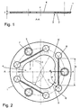
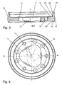
- Figures 1 and 2 show the three-point spring ring 1 in two views. Essential and evident is the complete 120 ° symmetry of the structures introduced into the three-point spring ring 1: spring 2, pressure surface 3, opening 4, countersunk holes 7, recesses 8. First, the three-point spring ring in the center of the free opening 4 for the unimpeded incidence of radiation on an optical part.
- Each of the springs 2 is formed by a dumbbell-shaped recess 8 of the spring ring. This design provides torsion axes 5 and 5 'that do not coincide with the axis of the bend 6.
- Each spring 2 acts as a spiral spring and as a torsion spring.
- Each of the springs 2 has a pressure surface 3, whose radius r is smaller than half the diameter of an optical part (denoted by the reference numeral 19 in FIG. 5). The optical part is touched only with the printing surfaces 3.
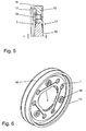
- Figures 3 and 4 show the mounting ring in two views.
- the mounting ring 10 also has a free opening 11 for the free entry of radiation.
- the radial version of the optical part is free of play, but without pressing in an inner lateral surface 15.
- the inner lateral surface 15 has on one side of the lens diameter protruding bearing surfaces 12. These serve as an axial stop for the optical part, which acts in only three points.
- the bearing surfaces 12 have the radius r, which corresponds to that of the springs 2.
- Threaded holes 13 are used for attachment and adjustment of the clamping force of the three-point spring ring 1 by screws.
- the socket 10 further has an outer fit 16, which is made by adjusting the rotation of the position of the optical part in the mounted mounting ring.
- the top surfaces 21 and 22 are made according to the position of the optical part in the mounted mounting ring, so that in a stacking several identical mounting rings air gaps of the optical parts and the centering state are maintained with high accuracy.
- the mounting ring further has cylindrical surfaces 23, 24 and 25.
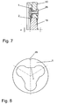
- Figure 5 shows a seized optical part 19 in section.
- the attachment of the three-point spring ring 1 is carried out with countersunk screws 18.
- the pressure surface 3 of the spring 2 presses against the stop surface 12 on the optical part 19th
- the three-point spring ring is not pressed against a stop surface 17 in the example. Rather, there is a sensitive adjustment of the cylinder head bolts 18 with a torque wrench.
- Figure 6 shows the captured optical part of FIG. 5 in a perspective view.
- the strict 120 ° symmetry and the comparatively low height in the axial direction can be seen.
- FIG. 7 shows an alternative embodiment of the invention dispensing with the three cylinder head bolts.
- the three-point spring ring 1 is connected here with three rivets 26.
- Figure 8 shows a three-point spring ring 1 with a design of the springs 2 as a simple leaf springs (effect only as a spiral spring).
- the attachment of the three-point spring ring 1 is provided with a snap ring, which is inserted into a groove of a cylindrical surface of the mounting ring 10.
- Another version uses a Vorschraubring which is screwed into the socket ring and the Three-point spring washer biases (not shown).
- the three-point spring ring has a notch 28, which corresponds to a corresponding mark in the socket ring, so as to ensure that the pressure surfaces 3 are exactly opposite the support surfaces 12 (see also Figure 3 and Figure 4 ).
Landscapes
- Physics & Mathematics (AREA)
- General Physics & Mathematics (AREA)
- Optics & Photonics (AREA)
- Mounting And Adjusting Of Optical Elements (AREA)
- Bolts, Nuts, And Washers (AREA)
- Lens Barrels (AREA)
- Registering, Tensioning, Guiding Webs, And Rollers Therefor (AREA)
- Photoreceptors In Electrophotography (AREA)
- Gyroscopes (AREA)
- Springs (AREA)
Description
- Die Erfindung bezeiht sich auf eine spannungsarme Optikfassung mit einem Fassungsring, dessen innere Mantelfläche der Aufnahme eines Optikteils dient, welches damit in einer radialen Richtung fixiert ist, wobei die Ausrichtung des Optikteils in einer axialen Richtung durch eine Auflagefläche bestimmt ist, die gegenüber der inneren Mantelfläche der radialen Richtung entgegengesetzt so hervorsteht, dass diese auf einem Rand einer ersten optischen Fläche des Optikteils anliegt und bei der ein Dreipunkt-Federring das Optikteil in der axialen Richtung dadurch fixiert, dass drei Federn des Dreipunkt-Federrings auf einem Rand einer zweiten optischen Fläche anliegen.
- Eine derartige Optikfassung ist aus der DE 75 37 569 U1 bekannt. Eine Linse ist in eine Fassung eingelegt. In radialer Richtung ist die Linse durch die innere Mantelfläche der Fassung fixiert. In axialer Richtung ist die Lage der Linse an einer Seite durch eine Auflagefläche bestimmt, deren Durchmesser kleiner als der Durchmesser der Linse ist. Von der anderen Seite her wird die Linse durch einen Federring gegen die Anlagefläche fixiert. Der Federring stützt sich gegen eine weitere Linse ab. Ein Distanzring, der gegen einen festen Anschlag geschraubt ist, legt den Luftabstand der beiden Linsen über die Durchbiegung des Federringes fest. Zwischen den beiden Linsen wird mittels des Federrings Spielfreiheit erzeugt.
Der Federring ist in einem Fall als Federscheibe mit wenigstens drei federnd aus der Scheibenfläche herausstehenden Zungen ausgebildet. In einem anderen Fall ist der Federring als Wellenfeder mit wenigstens drei am Umfang verteilten Wellen ausgebildet. Mit derartigen Anordnungen ist eine spannungsarme Fassung eines Optikteils nicht gewährleistet, weil der Lagebezug der Feder zur Fassung nicht eindeutig ist. Die herausstehenden Zungen bzw. die Wellen der Feder benötigen eine gewisse Bauhöhe in axialer Richtung. - Die DE 101 39 805 C1 und die DE 100 43 344 A1 beschreiben eine spannungsarme Linsenfassung, die eine in die Umfangsfläche der Linse eingefräste Ringnut verwendet, in die drei tragende Elemente eingreifen. Allein die bei der Herstellung der Ringnut erzeugten Kerbspannungen lassen die Lösung für eine Verwendung der Linse für Hochleistungssysteme, die insbesondere bei Wellenlängen im UV-Bereich als nicht geeignet bewerten.
- Der Erfindung liegt die Aufgabe zu Grunde, eine neue spannungsarme Optikfassung zu liefern. Die Andruckkraft des Dreipunkt-Federrings soll unabhängig von anderen Anforderungen einstellbar oder nur durch die Dimensionierung der Teile vorgegeben sein. Ein oder mehrere Optikteile eines Systems soll individuell mit jeweils einem Dreipunkt-Federring gesichert werden. Die Bauhöhe in axialer Richtung soll minimiert werden. Dabei soll eine Einfache Demontierbarkeit komplexer optischer Systeme gewährleistet sei, so dass Reparaturen defekter Optikteile vergleichsweise einfach ausführbar sind.
- Gemäß der Erfindung wird die Aufgabe durch eine Optikfassung der Eingangs genannten Art durch die kennzeichnenden Merkmale des Anspruchs 1 gelöst. Die Unteransprüche 2 bis 8 sind vorteilhafte Ausgestaltungen des Anspruches 1.
Die Auflagefläche des Fassungsringes weist drei Segmente auf, die bezogen auf den Umfang der inneren Mantelfläche verteilt sind und auf dem Rand der ersten optischen Fläche des Optikteils anliegen. Der Dreipunkt-Federring ist mit dem Fassungsring so verbunden, dass jeweils eine segmentförmige Druckfläche der drei Federn des Dreipunkt-Federringes der radialen Richtung entgegengesetzt nur soweit hervorsteht, dass diese nur in dem Flächenbereich, der einer Auflagefläche des Fassungsringes in der axialen Richtung gegenüberliegt auf dem Rand der zweiten optischen Fläche des Optikteils drückt. Der Dreipunkt-Federring hat drei Federn, die segmentförmige Druckflächen bilden, die nur in den Flächenbereichen, die den Auflageflächen gegenüberliegen, auf das dem Rand der zweiten optischen Fläche des Optikteils drücken.
Somit ist eine punktuelle Krafteinleitung geschaffen, die nur auf die gegenüberliegenden Auflageflächen des Fassungsringes wirkt. Die Haltekräfte sind symmetrisch verteilt und regulierbar. Der gegenüberliegende Kraftangriff reduziert die Deformation des Optikteils auf ein Minimum. Die leichte Demontierbarkeit der Fassung ermöglicht den einfachen Austausch defekter Optikteile. Eine spannungsarme Halterung der Optikteile ist insbesondere bei Optikeinheiten, bei denen es auf hohes Auflösungsvermögen ankommt und die mit kurzen Wellenlängen arbeiten, erforderlich (z.B. für Anwendungen in der Mikroelektronikindustrie). Die optischen Funktionsflächen stehen unter hohen Toleranzforderungen bezüglich Deformation, um die optische Leistung der Systeme zu gewährleisten. Durch die erfindungsgemäße Lösung werden nur Materialien eingesetzt, die gegenüber der aggressiven Strahlung resistent sind, z.B. Stahl, Messing. Insbesondere wird auf organische Materialien, wie z.B. Kleber verzichtet.
Die Optikfassung hat eine vergleichsweise geringe Bauhöhe, die in etwa der Dicke des Optikteils entspricht. So können auch kleinste Luftabstände zwischen mehreren hintereinandergefügten Optikteilen realisiert werden. Die Optikfassung hat auch eine vergleichsweise geringe radiale Ausdehnung, da die Federn nur einen geringen Platzbedarf haben. - Der Dreipunkt-Federring ist im unverbauten, spannungslosen Zustand vorzugsweise eben, mit parallel zueinander stehenden Ringflächen. Dies gewährleistet eine minimale Aufbauhöhe der Fassung in axialer Richtung. Ein solches Teil ist auch besonders kostengünstig herstellbar. Der Dreipunkt-Federring ist vergleichsweise dünn (Verhältnis Dicke zu Durchmesser ist in der Größenordnung1:100), so dass kleine Federkräfte zur Wirkung kommen. Der Dreipunkt-Federring dient ausschließlich zur Fixierung der Optik in dem Fassungsring. Die Ausrichtung der Optik kann durch Justierdrehen des Fassungsringes nach der optischen Achse des Optikteils erfolgen, wenn die zu erreichende Zentriergenauigkeit dieses erforderlich macht.
- Eine vorteilhafte Ausgestaltung erfährt der Dreipunkt-Federring dadurch, dass dieser in seiner Ringfläche drei Ausnehmungen aufweist, welche die Ringfläche in vier Bereiche aufteilen, wobei ein außen liegender Bereich der Befestigung des Dreipunkt-Federringes mit dem Fassungsring dient und drei zentrumsnahe Bereiche als zweiarmig gelagerte Federn ausgebildet sind, die eine gleiche Federsteifigkeit aufweisen und nur ein Teil der Federn nur soweit in Richtung auf die Achse des Optikteils hervorstehen, dass diese auf dem Rand der optischen Fläche des Optikteils drücken. Der außen liegende Bereich dient zur Befestigung des Dreipunkt-Federringes mit dem Fassungsring und sorgt im montierten Zustand für die Vorspannung der Federn.
Diese Federn sind besonders geeignet, da diese sowohl als Biegefeder als auch als Torsionsfeder beansprucht werden. - Vorzugsweise ist jede der Ausnehmungen spiegelsymmetrisch. Dabei sind die Torsionsachsen jeder der Federn mit einem gleichen Abstand a und unter einem gleichen Winkel α bezogen zur Symmetrieachse angeordnet. Jede der Federn erhält somit definierte Eigenschaften.
Der Abstand a entspricht in etwa dem Durchmesser des zu fassenden Optikteils. - Eine weitere vorteilhafte Ausgestaltung ist dadurch gegeben, dass die Ausnehmungen einen hantelförmigen Querschnitt aufweisen. Eine solche Form vermeidet scharfe Übergänge und somit Kerbspannungen, und schafft separate definierte Federelemente. Bei der Montage der Teile werden unbestimmte Verbiegungen sicher vermieden.
- Ein weiteres vorteilhaftes Merkmal ist, dass die Segmente der Auflageflächen in einem Winkel von 120° angeordnet sind und der Dreipunkt-Federring eine der 120° Teilung entsprechende Symmetrie aufweist.
- Insbesondere sind alle Löcher, die Druckflächen und die Ausnehmungen in dem Dreipunkt-Federring symmetrisch. Die drei Federn haben somit weitestgehend identische Eigenschaften. Ein spannungsoptimierter Einbau des Optikteils in die Fassung ist gegeben.
- In einer Ausführungsform weist der Dreipunk-Federring zur Befestigung drei Löcher auf. Mittels drei Schrauben wird der Dreipunkt-Federring mit dem Fassungsring verschraubt. Um die Bauhöhe zu minimieren, sind die Löcher als kegelförmige Senklöcher ausgebildet. Die Schrauben sind Zylinderkopfschrauben.
Die Anzugskraft der Schrauben kann bei der Verschraubung mittels eines Drehmomentschlüssels überwacht werden, so dass jede der Federn definiert vorgespannt wird und genau bemessene Kräfte auf das Optikteil einwirken. - Eine weitere Ausführungsform zur Befestigung des Dreipunkt-Federringes besteht darin, diesen mittels eines Sprengringes zu befestigen, der in eine Nut eingreift, die in einer Zylinderfläche des Fassungsringes eingebracht ist. Der Federring wird gegen eine Anlagefläche des Fassungsringes gedrückt und die Haltekräfte für das Optikteil werden durch die Dimensionierung des Dreipunkt-Federringes bestimmt. Diese Alternative zur Schraubverbindung ist kostengünstiger.
Jedoch können auch andere Befestigungsarten Anwendung finden, wie z.B. ein Vorschraubring, Nieten oder eine snap-in-Verbindung. - Die Erfindung wird nachfolgend an Hand von Ausführungsbeispielen näher erläutert werden. In den Zeichnungen zeigen:
- Fig. 1:
- Dreipunkt Federring im Schnitt A-A
- Fig. 2:
- Dreipunkt-Federring in der Draufsicht
- Fig. 3:
- Fassungsring im Schnitt B-B
- Fig. 4:
- Fassungsring in der Draufsicht
- Fig. 5:
- Gefasstes Optikteil im Schnitt, Befestigung durch Senkkopfschrauben
- Fig. 6
- Gefasstes Optikteil gemäß Fig. 5 in einer perspektivischen Darstellung
- Fig. 7:
- Gefasstes Optikteil im Schnitt, Befestigung durch Nietverbindung
- Fig. 8
- Eine andere Ausführung des Dreipunkt-Federrings
- Die Figuren 1 und 2 zeigen den Dreipunkt Federring 1 in zwei Ansichten. Wesentlich und augenscheinlich ist die vollständige 120° Symmetrie der in den Dreipunkt-Federring 1 eingebrachten Strukturen: Feder 2, Druckfläche 3, Öffnung 4, angesenkte Löcher 7, Ausnehmungen 8.
Zunächst hat der Dreipunkt-Federring im Zentrum die freie Öffnung 4 für den ungehinderten Einfall der Strahlung auf ein Optikteil.
Jede der Federn 2 ist durch eine hantelförmige Ausnehmung 8 aus dem Federring herausgebildet. Diese Gestaltung liefert Torsionsachsen 5 und 5', die nicht mit der Achse der Verbiegung 6 übereinstimmen. Jede Feder 2 wirkt als Biegefeder und als Torsionsfeder. Zusammen mit der Länge a (Wirkung als Biegefeder), der Stegbreite b (Wirkung als Torsionsfeder), der Dicke c, und Breite d im Bereich der Druckfläche (Wirkung als Biegefeder) sowie der Materialart führt dies zu den gewünschten Federeigenschaften.
Jede der Federn 2 hat eine Druckfläche 3, deren Radius r kleiner ist als der halbe Durchmesser eines Optikteils (In Figur 5 mit dem Bezugszeichen 19 bezeichnet). Das Optikteil wird nur mit den Druckflächen 3 berührt. - Die Figuren 3 und 4 zeigen den Fassungsring in zwei Ansichten. Der Fassungsring 10 hat ebenfalls eine freie Öffnung 11 für den freien Eintritt von Strahlung. Die radiale Fassung des Optikteils erfolgt spielfrei, jedoch ohne Pressungen in einer inneren Mantelfläche 15. Die innere Mantelfläche 15 hat an einer Seite über den Linsendurchmesser hervorstehende Auflageflächen 12. Diese dienen als axialer Anschlag für das Optikteil, der in nur drei Punkten wirkt. Die Auflageflächen 12 haben den Radius r, der dem der Federn 2 entspricht.
- Gewindebohrungen 13 dienen zur Befestigung und Einstellung der Spannkraft des Dreipunkt-Federringes 1 durch Schrauben.
Die Fassung 10 hat weiterhin eine Außenpassung 16, die durch Justierdrehen nach der Lage des Optikteils in dem montierten Fassungsring gefertigt wird. Weiterhin werden die Deckflächen 21 und 22 nach der Lage des Optikteils in der montierten Fassungsring gefertigt, so dass bei einer Stapelung mehrere gleichartiger Fassungsringe Luftabstände der Optikteile und der Zentrierzustand mit hoher Genauigkeit eingehalten werden. Der Fassungsring weist weiterhin Zylinderflächen 23, 24 und 25 auf. - Figur 5 zeigt ein gefasstes Optikteil 19 im Schnitt. Die Befestigung des Dreipunkt-Federringes 1 erfolgt mit Senkkopfschrauben 18. Die Druckfläche 3 der Feder 2 drückt gegenüber der Anschlagfläche 12 auf das Optikteil 19.
Dabei wird der Dreipunkt-Federring im Beispiel nicht gegen eine Anschlagfläche 17 gedrückt. Vielmehr erfolgt eine feinfühlig Einstellung der Zylinderkopfschrauben 18 mit einem Drehmomentschlüssel. - Figur 6 zeigt das gefasstes Optikteil gemäß Fig. 5 in einer perspektivischen Darstellung. Hier sind insbesondere die strenge 120°-Symmetrie und die vergleichsweise geringe Bauhöhe in axialer Richtung ersichtlich.
- Die Figur 7 zeigt ein alternative Ausführungsform der Erfindung, die auf die drei Zylinderkopfschrauben verzichtet. Der Dreipunkt-Federring 1 wird hier mit drei Nieten 26 verbunden.
- Die Figur 8 zeigt einem Dreipunkt-Federring 1 mit einen Ausbildung der Federn 2 als einfache Blattfedern (Wirkung nur als Biegefeder).
In diesem Beispiel ist die Befestigung des Dreipunkt-Federringes 1 mit einem Sprengring vorgesehen, der in eine Nut einer Zylinderfläche des Fassungsringes 10 eingelegt ist. Eine andere Ausführung verwendet einen Vorschraubring, der in den Fassungsring eingeschraubt wird und den Dreipunkt-Federring vorspannt (nicht dargestellt). Bei den zu dieser Figur beschriebenen Befestigungsarten hat der Dreipunkt-Federring eine Einkerbung 28, die mit einer entsprechenden Marke in dem Fassungsring korrespondiert, so dass sichergestellt ist, dass die Druckflächen 3 genau gegenüber den Auflageflächen 12 liegen (siehe dazu auch Figur 3 und Figur 4). -
- 1
- Dreipunkt-Federring
- 2
- Feder
- 3
- Druckfläche
- 4
- Öffnung
- 5
- Torsionsachse
- 6
- Achse der Verbiegung
- 7
- angesenktes Loch
- 8
- Ausnehmung
- 9
- Senkung
- 10
- Fassungsring
- 11
- Öffnung
- 12
- Auflagefläche
- 13
- Gewindebohrung
- 14
- Loch
- 15
- innere Mantelfläche
- 16
- Außenpassung
- 17
- Anschlagfläche
- 18
- Senkkopfschraube
- 19
- Optikteil
- 21
- Deckfläche
- 22
- Deckfläche
- 23
- Zylinderfläche
- 24
- Zylinderfläche
- 25
- Zylinderfläche
- 26
- Niet
- 28
- Einkerbung
- a
- Länge
- b
- Stegbreite
- c
- Dicke
- d
- Breite
- r
- Radius
- z
- axiale Richtung
(Symmetrieachse) - α
- Winkellage der Torsionsachsen
Claims (8)
- Spannungsarme Optikfassung mit einem Fassungsring (10), dessen innere Mantelfläche (15) der Aufnahme eines Optikteils (19) dient, welches damit in einer radialen Richtung (r) zu fixieren ist, wobei die Ausrichtung des Optikteils (19) in einer axialen Richtung (z) durch eine Auflagefläche (12) bestimmt ist, die von der inneren Mantelfläche (15) nach innen so hervorsteht, dass die Auflagefläche auf einem Rand einer ersten optischen Fläche des Optikteils (19) zum Anliegen kommt und bei der ein Dreipunkt-Federring (1) das Optikteil (19) in der axialen Richtung (z) dadurch fixiert, dass drei Federn des Dreipunkt-Federrings (1) auf einem Rand einer zweiten optischen Fläche zum Anliegen kommen,
dadurch gekennzeichnet, dass
die Auflagefläche (12) des Fassungsringes (10) drei Segmente aufweist, die bezogen auf den Umfang der inneren Mantelfläche (15) verteilt sind und auf dem Rand der ersten optischen Fläche des Optikteils (19) zum Anliegen kommen sowie, dass der Dreipunkt-Federring (1) mit dem Fassungsring (10) so verbunden ist, dass jeweils eine segmentförmige Druckfläche (3) der drei Federn (2) des Dreipunkt-Federringes (1) in der radialen Richtung (r) nur soweit nach innen hervorsteht, dass diese nur in dem Flächenbereich, der einer Auflagefläche (12) des Fassungsringes (10) in der axialen Richtung (z) gegenüberliegt, auf dem Rand der zweiten optischen Fläche des Optikteils (19) drückt. - Optikfassung nach Anspruch 1, dadurch gekennzeichnet, dass
der Dreipunkt-Federring (1) im unverspannten Zustand ebene, parallel zueinander stehende Ringflächen hat. - Optikfassung nach Anspruch 1, dadurch gekennzeichnet, dass der Dreipunkt-Federring (1) in seiner Ringfläche drei Ausnehmungen (8) aufweist, welche die Ringfläche in vier Bereiche aufteilen, wobei ein außen liegender Bereich der Befestigung des Dreipunkt-Federringes (1) mit dem Fassungsring (10) dient und drei zentrumsnahe Bereiche als zweiarmig gelagerte Federn (2) ausgebildet sind, die eine gleiche Federsteifigkeit aufweisen.
- Optikfassung nach Anspruch 2, dadurch gekennzeichnet, dass jede der Ausnehmungen (8) spiegelsymmetrisch ist und Torsionsachsen jeder der Federn (2) mit einem gleichen Abstand a und unter einem gleichen Winkel α bezogen zur Symmetrieachse angeordnet sind.
- Optikfassung nach Anspruch 3, dadurch gekennzeichnet, dass
die Ausnehmungen (8) einen hantelförmigen Querschnitt aufweisen. - Optikfassung nach Anspruch 1 oder Anspruch 5, dadurch gekennzeichnet, dass
die Segmente der Auflageflächen (12) in einem Winkel von 120° angeordnet sind und der Dreipunkt-Federring (1) eine der 120° Teilung entsprechende Symmetrie aufweist. - Optikfassung nach Anspruch 1, dadurch gekennzeichnet, dass
der Dreipunkt-Federring (1) drei Löcher (14) aufweist und dieser mittels drei Schrauben mit dem Fassungsring (10) verschraubt ist. - Optikfassung nach Anspruch 1, dadurch gekennzeichnet, dass
der Dreipunkt-Federring (1) mittels eines in eine Zylinderfläche (23) des Fassungsringes (10) eingreifenden Sprengringes, snap-in-Verbindung oder Vorschraubringes befestigt ist oder die Verbindung durch Nieten erfolgt.
Applications Claiming Priority (2)
| Application Number | Priority Date | Filing Date | Title |
|---|---|---|---|
| DE10342269A DE10342269A1 (de) | 2003-09-12 | 2003-09-12 | Spannungsarme Optikfassung |
| DE10342269 | 2003-09-12 |
Publications (2)
| Publication Number | Publication Date |
|---|---|
| EP1515172A1 EP1515172A1 (de) | 2005-03-16 |
| EP1515172B1 true EP1515172B1 (de) | 2006-12-13 |
Family
ID=34129791
Family Applications (1)
| Application Number | Title | Priority Date | Filing Date |
|---|---|---|---|
| EP04021071A Expired - Lifetime EP1515172B1 (de) | 2003-09-12 | 2004-09-04 | Spannungsarme Optikfassung |
Country Status (3)
| Country | Link |
|---|---|
| EP (1) | EP1515172B1 (de) |
| AT (1) | ATE348346T1 (de) |
| DE (2) | DE10342269A1 (de) |
Families Citing this family (5)
| Publication number | Priority date | Publication date | Assignee | Title |
|---|---|---|---|---|
| DE102008039788B3 (de) * | 2008-08-26 | 2010-04-01 | Carl Zeiss Ag | Spannungsarme Optikfassung |
| DE102010022934A1 (de) | 2010-06-04 | 2011-12-08 | Carl Zeiss Ag | Optische Baugruppe |
| DE102013109263B4 (de) * | 2013-08-27 | 2016-04-21 | Jos. Schneider Optische Werke Gmbh | Fassung für ein Optikelement, optisches System und Verwendung eines radial federnden Rings |
| DE102014109912B3 (de) | 2014-07-15 | 2015-08-06 | Jenoptik Optical Systems Gmbh | Linsenfassung mit Zwischenring |
| CN111061026B (zh) * | 2019-12-30 | 2025-02-11 | 中山联合光电科技股份有限公司 | 一种快速调节镜片同轴度的结构 |
Family Cites Families (9)
| Publication number | Priority date | Publication date | Assignee | Title |
|---|---|---|---|---|
| DE1708751U (de) * | 1955-02-26 | 1955-10-13 | Zeiss Ikon Ag | Befestigungseinrichtung fuer kreisscheibenfoermige optische bauteile. |
| DE1865707U (de) * | 1962-10-04 | 1963-01-17 | Schneider Co Optische Werke | Halterung von linsen od. dgl. |
| DE7537569U (de) * | 1975-11-26 | 1976-04-01 | Rollei-Werke Franke & Heidecke, 3300 Braunschweig | Fotografisches objektiv |
| JP3300538B2 (ja) * | 1994-08-15 | 2002-07-08 | キヤノン株式会社 | レンズホルダー |
| JP2002505790A (ja) * | 1998-04-17 | 2002-02-19 | コーニンクレッカ フィリップス エレクトロニクス エヌ ヴィ | コンパクトなアクチュエータを有するレンズシステムからなる光学走査装置 |
| DE10043344C2 (de) * | 1999-10-06 | 2001-12-13 | Jenoptik Jena Gmbh | Elastische Linsenträger |
| JP2002236242A (ja) * | 2001-02-09 | 2002-08-23 | Nikon Corp | 光学素子保持装置、鏡筒及び露光装置並びにマイクロデバイスの製造方法 |
| DE10139805C1 (de) * | 2001-08-13 | 2002-10-10 | Jenoptik Laser Optik Sys Gmbh | Spannungsarme Linsenfassung |
| JP3650605B2 (ja) * | 2002-01-28 | 2005-05-25 | ペンタックス株式会社 | レンズ保持装置 |
-
2003
- 2003-09-12 DE DE10342269A patent/DE10342269A1/de not_active Ceased
-
2004
- 2004-09-04 EP EP04021071A patent/EP1515172B1/de not_active Expired - Lifetime
- 2004-09-04 DE DE502004002271T patent/DE502004002271D1/de not_active Expired - Lifetime
- 2004-09-04 AT AT04021071T patent/ATE348346T1/de not_active IP Right Cessation
Also Published As
| Publication number | Publication date |
|---|---|
| DE10342269A1 (de) | 2005-04-14 |
| EP1515172A1 (de) | 2005-03-16 |
| DE502004002271D1 (de) | 2007-01-25 |
| ATE348346T1 (de) | 2007-01-15 |
Similar Documents
| Publication | Publication Date | Title |
|---|---|---|
| DE10042844C1 (de) | Radial justierbare Linsenfassung | |
| DE102013109185B3 (de) | Optische Baugruppe mit einer Fassung mit Verbindungseinheiten gerichteter Nachgiebigkeit | |
| DE19724246B4 (de) | Einstellvorrichtung für ein Objektiv einer CCTV-Kamera | |
| DE2915030A1 (de) | Montagevorrichtung fuer optisches element | |
| WO2017102558A1 (de) | Spannvorrichtung für werkstücke | |
| DE102012206252A1 (de) | Kameramodul und Verfahren zum Herstellen eines Kameramoduls | |
| DE2233639A1 (de) | Halterung fuer optische bauelemente, insbesondere in einem lasersystem | |
| EP3569352B1 (de) | Spannelement eines spannsystems, insbesondere eines nullpunktspannsystems, und spannsystem | |
| DE102008035224B4 (de) | Laseroszillator mit einer Befestigungskonstruktion für ein optisches Element | |
| WO2020126842A1 (de) | ULTRASCHALLSCHWEIßANLAGE MIT HALTERUNG | |
| DE102013113639B3 (de) | Befestigungsvorrichtung zum konzentrischen Befestigen einer Welle an eine Drehgeberwelle und Motorfeedback-System mit dieser Befestigung | |
| DE19804470C1 (de) | Mikroskopobjektiv mit einer Korrekturfassung | |
| EP1706654B1 (de) | Gewindering | |
| EP1515172B1 (de) | Spannungsarme Optikfassung | |
| DE102018132840A1 (de) | Ultraschallschweißanlage mit formschlüssiger Verbindung | |
| EP2606390B1 (de) | Mehrstufig justierbare fassungsbaugruppe für zwei optische bauteile | |
| DE202013105568U1 (de) | Befestigungsvorrichtung zum konzentrischen Befestigen einer Welle an eine Drehgeberwelle und Motorfeedback-System mit dieser Befestigung | |
| EP3765883B1 (de) | Justierfassung zur radialen justierung einer optischen einheit mit einer optischen achse | |
| DE102013109605B3 (de) | Optische Baugruppe mit einer monolithischen Fassung mit in einer gleichen Richtung wirkenden Stellschrauben | |
| DE102021107412B3 (de) | Kompakte Justierfassung zur Justierung eines optischen Tubus | |
| DE102014105705A1 (de) | Schneidwerkzeug | |
| EP2177778B1 (de) | Lageraufnahme in einem Lagerschild | |
| EP2065684B1 (de) | Justiermittel und dazugehöriger Körper mit einer Skalierung sowie Verfahren zum Justieren | |
| DE202021104369U1 (de) | Schrumpffutter | |
| DE102008039788B3 (de) | Spannungsarme Optikfassung |
Legal Events
| Date | Code | Title | Description |
|---|---|---|---|
| PUAI | Public reference made under article 153(3) epc to a published international application that has entered the european phase |
Free format text: ORIGINAL CODE: 0009012 |
|
| 17P | Request for examination filed |
Effective date: 20040904 |
|
| AK | Designated contracting states |
Kind code of ref document: A1 Designated state(s): AT BE BG CH CY CZ DE DK EE ES FI FR GB GR HU IE IT LI LU MC NL PL PT RO SE SI SK TR |
|
| AX | Request for extension of the european patent |
Extension state: AL HR LT LV MK |
|
| 17Q | First examination report despatched |
Effective date: 20050527 |
|
| AKX | Designation fees paid |
Designated state(s): AT BE BG CH CY CZ DE DK EE ES FI FR GB GR HU IE IT LI LU MC NL PL PT RO SE SI SK TR |
|
| GRAP | Despatch of communication of intention to grant a patent |
Free format text: ORIGINAL CODE: EPIDOSNIGR1 |
|
| GRAS | Grant fee paid |
Free format text: ORIGINAL CODE: EPIDOSNIGR3 |
|
| GRAA | (expected) grant |
Free format text: ORIGINAL CODE: 0009210 |
|
| AK | Designated contracting states |
Kind code of ref document: B1 Designated state(s): AT BE BG CH CY CZ DE DK EE ES FI FR GB GR HU IE IT LI LU MC NL PL PT RO SE SI SK TR |
|
| PG25 | Lapsed in a contracting state [announced via postgrant information from national office to epo] |
Ref country code: IT Free format text: LAPSE BECAUSE OF FAILURE TO SUBMIT A TRANSLATION OF THE DESCRIPTION OR TO PAY THE FEE WITHIN THE PRESCRIBED TIME-LIMIT;WARNING: LAPSES OF ITALIAN PATENTS WITH EFFECTIVE DATE BEFORE 2007 MAY HAVE OCCURRED AT ANY TIME BEFORE 2007. THE CORRECT EFFECTIVE DATE MAY BE DIFFERENT FROM THE ONE RECORDED. Effective date: 20061213 Ref country code: SK Free format text: LAPSE BECAUSE OF FAILURE TO SUBMIT A TRANSLATION OF THE DESCRIPTION OR TO PAY THE FEE WITHIN THE PRESCRIBED TIME-LIMIT Effective date: 20061213 Ref country code: DK Free format text: LAPSE BECAUSE OF FAILURE TO SUBMIT A TRANSLATION OF THE DESCRIPTION OR TO PAY THE FEE WITHIN THE PRESCRIBED TIME-LIMIT Effective date: 20061213 Ref country code: CZ Free format text: LAPSE BECAUSE OF FAILURE TO SUBMIT A TRANSLATION OF THE DESCRIPTION OR TO PAY THE FEE WITHIN THE PRESCRIBED TIME-LIMIT Effective date: 20061213 Ref country code: SI Free format text: LAPSE BECAUSE OF FAILURE TO SUBMIT A TRANSLATION OF THE DESCRIPTION OR TO PAY THE FEE WITHIN THE PRESCRIBED TIME-LIMIT Effective date: 20061213 Ref country code: RO Free format text: LAPSE BECAUSE OF FAILURE TO SUBMIT A TRANSLATION OF THE DESCRIPTION OR TO PAY THE FEE WITHIN THE PRESCRIBED TIME-LIMIT Effective date: 20061213 Ref country code: PL Free format text: LAPSE BECAUSE OF FAILURE TO SUBMIT A TRANSLATION OF THE DESCRIPTION OR TO PAY THE FEE WITHIN THE PRESCRIBED TIME-LIMIT Effective date: 20061213 Ref country code: NL Free format text: LAPSE BECAUSE OF FAILURE TO SUBMIT A TRANSLATION OF THE DESCRIPTION OR TO PAY THE FEE WITHIN THE PRESCRIBED TIME-LIMIT Effective date: 20061213 Ref country code: IE Free format text: LAPSE BECAUSE OF FAILURE TO SUBMIT A TRANSLATION OF THE DESCRIPTION OR TO PAY THE FEE WITHIN THE PRESCRIBED TIME-LIMIT Effective date: 20061213 Ref country code: FI Free format text: LAPSE BECAUSE OF FAILURE TO SUBMIT A TRANSLATION OF THE DESCRIPTION OR TO PAY THE FEE WITHIN THE PRESCRIBED TIME-LIMIT Effective date: 20061213 |
|
| REG | Reference to a national code |
Ref country code: GB Ref legal event code: FG4D Free format text: NOT ENGLISH |
|
| REG | Reference to a national code |
Ref country code: CH Ref legal event code: EP |
|
| REG | Reference to a national code |
Ref country code: IE Ref legal event code: FG4D Free format text: LANGUAGE OF EP DOCUMENT: GERMAN |
|
| GBT | Gb: translation of ep patent filed (gb section 77(6)(a)/1977) |
Effective date: 20061229 |
|
| REF | Corresponds to: |
Ref document number: 502004002271 Country of ref document: DE Date of ref document: 20070125 Kind code of ref document: P |
|
| PG25 | Lapsed in a contracting state [announced via postgrant information from national office to epo] |
Ref country code: BG Free format text: LAPSE BECAUSE OF FAILURE TO SUBMIT A TRANSLATION OF THE DESCRIPTION OR TO PAY THE FEE WITHIN THE PRESCRIBED TIME-LIMIT Effective date: 20070313 Ref country code: SE Free format text: LAPSE BECAUSE OF FAILURE TO SUBMIT A TRANSLATION OF THE DESCRIPTION OR TO PAY THE FEE WITHIN THE PRESCRIBED TIME-LIMIT Effective date: 20070313 |
|
| PG25 | Lapsed in a contracting state [announced via postgrant information from national office to epo] |
Ref country code: ES Free format text: LAPSE BECAUSE OF FAILURE TO SUBMIT A TRANSLATION OF THE DESCRIPTION OR TO PAY THE FEE WITHIN THE PRESCRIBED TIME-LIMIT Effective date: 20070324 |
|
| PG25 | Lapsed in a contracting state [announced via postgrant information from national office to epo] |
Ref country code: PT Free format text: LAPSE BECAUSE OF FAILURE TO SUBMIT A TRANSLATION OF THE DESCRIPTION OR TO PAY THE FEE WITHIN THE PRESCRIBED TIME-LIMIT Effective date: 20070514 |
|
| ET | Fr: translation filed | ||
| NLV1 | Nl: lapsed or annulled due to failure to fulfill the requirements of art. 29p and 29m of the patents act | ||
| PLBE | No opposition filed within time limit |
Free format text: ORIGINAL CODE: 0009261 |
|
| STAA | Information on the status of an ep patent application or granted ep patent |
Free format text: STATUS: NO OPPOSITION FILED WITHIN TIME LIMIT |
|
| 26N | No opposition filed |
Effective date: 20070914 |
|
| BERE | Be: lapsed |
Owner name: CARL ZEISS SMS G.M.B.H. Effective date: 20070930 |
|
| PG25 | Lapsed in a contracting state [announced via postgrant information from national office to epo] |
Ref country code: GR Free format text: LAPSE BECAUSE OF FAILURE TO SUBMIT A TRANSLATION OF THE DESCRIPTION OR TO PAY THE FEE WITHIN THE PRESCRIBED TIME-LIMIT Effective date: 20070314 Ref country code: MC Free format text: LAPSE BECAUSE OF NON-PAYMENT OF DUE FEES Effective date: 20070930 |
|
| PG25 | Lapsed in a contracting state [announced via postgrant information from national office to epo] |
Ref country code: BE Free format text: LAPSE BECAUSE OF NON-PAYMENT OF DUE FEES Effective date: 20070930 |
|
| PG25 | Lapsed in a contracting state [announced via postgrant information from national office to epo] |
Ref country code: AT Free format text: LAPSE BECAUSE OF NON-PAYMENT OF DUE FEES Effective date: 20070904 |
|
| PG25 | Lapsed in a contracting state [announced via postgrant information from national office to epo] |
Ref country code: EE Free format text: LAPSE BECAUSE OF FAILURE TO SUBMIT A TRANSLATION OF THE DESCRIPTION OR TO PAY THE FEE WITHIN THE PRESCRIBED TIME-LIMIT Effective date: 20061213 |
|
| PG25 | Lapsed in a contracting state [announced via postgrant information from national office to epo] |
Ref country code: LU Free format text: LAPSE BECAUSE OF NON-PAYMENT OF DUE FEES Effective date: 20070904 Ref country code: CY Free format text: LAPSE BECAUSE OF FAILURE TO SUBMIT A TRANSLATION OF THE DESCRIPTION OR TO PAY THE FEE WITHIN THE PRESCRIBED TIME-LIMIT Effective date: 20061213 |
|
| PG25 | Lapsed in a contracting state [announced via postgrant information from national office to epo] |
Ref country code: HU Free format text: LAPSE BECAUSE OF FAILURE TO SUBMIT A TRANSLATION OF THE DESCRIPTION OR TO PAY THE FEE WITHIN THE PRESCRIBED TIME-LIMIT Effective date: 20070614 Ref country code: TR Free format text: LAPSE BECAUSE OF FAILURE TO SUBMIT A TRANSLATION OF THE DESCRIPTION OR TO PAY THE FEE WITHIN THE PRESCRIBED TIME-LIMIT Effective date: 20061213 |
|
| REG | Reference to a national code |
Ref country code: CH Ref legal event code: PFA Owner name: CARL ZEISS SMS GMBH Free format text: CARL ZEISS SMS GMBH#CARL-ZEISS-PROMENADE 10#07745 JENA (DE) -TRANSFER TO- CARL ZEISS SMS GMBH#CARL-ZEISS-PROMENADE 10#07745 JENA (DE) |
|
| REG | Reference to a national code |
Ref country code: DE Ref legal event code: R081 Ref document number: 502004002271 Country of ref document: DE Owner name: CARL ZEISS SMT GMBH, DE Free format text: FORMER OWNER: CARL ZEISS SMS GMBH, 07745 JENA, DE |
|
| REG | Reference to a national code |
Ref country code: FR Ref legal event code: PLFP Year of fee payment: 13 |
|
| REG | Reference to a national code |
Ref country code: FR Ref legal event code: TP Owner name: CARL ZEISS SMT GMBH, DE Effective date: 20161019 |
|
| REG | Reference to a national code |
Ref country code: GB Ref legal event code: 732E Free format text: REGISTERED BETWEEN 20170202 AND 20170208 |
|
| REG | Reference to a national code |
Ref country code: FR Ref legal event code: PLFP Year of fee payment: 14 |
|
| REG | Reference to a national code |
Ref country code: FR Ref legal event code: PLFP Year of fee payment: 15 |
|
| REG | Reference to a national code |
Ref country code: CH Ref legal event code: PFUS Owner name: CARL ZEISS SMT GMBH, DE Free format text: FORMER OWNER: CARL ZEISS SMS GMBH, DE |
|
| PGFP | Annual fee paid to national office [announced via postgrant information from national office to epo] |
Ref country code: GB Payment date: 20200922 Year of fee payment: 17 Ref country code: FR Payment date: 20200914 Year of fee payment: 17 |
|
| PGFP | Annual fee paid to national office [announced via postgrant information from national office to epo] |
Ref country code: CH Payment date: 20200921 Year of fee payment: 17 |
|
| REG | Reference to a national code |
Ref country code: CH Ref legal event code: PL |
|
| GBPC | Gb: european patent ceased through non-payment of renewal fee |
Effective date: 20210904 |
|
| PG25 | Lapsed in a contracting state [announced via postgrant information from national office to epo] |
Ref country code: GB Free format text: LAPSE BECAUSE OF NON-PAYMENT OF DUE FEES Effective date: 20210904 Ref country code: FR Free format text: LAPSE BECAUSE OF NON-PAYMENT OF DUE FEES Effective date: 20210930 |
|
| PG25 | Lapsed in a contracting state [announced via postgrant information from national office to epo] |
Ref country code: LI Free format text: LAPSE BECAUSE OF NON-PAYMENT OF DUE FEES Effective date: 20210930 Ref country code: CH Free format text: LAPSE BECAUSE OF NON-PAYMENT OF DUE FEES Effective date: 20210930 |
|
| P01 | Opt-out of the competence of the unified patent court (upc) registered |
Effective date: 20230525 |
|
| PGFP | Annual fee paid to national office [announced via postgrant information from national office to epo] |
Ref country code: DE Payment date: 20230920 Year of fee payment: 20 |
|
| REG | Reference to a national code |
Ref country code: DE Ref legal event code: R071 Ref document number: 502004002271 Country of ref document: DE |