EP3569352B1 - Spannelement eines spannsystems, insbesondere eines nullpunktspannsystems, und spannsystem - Google Patents
Spannelement eines spannsystems, insbesondere eines nullpunktspannsystems, und spannsystem Download PDFInfo
- Publication number
- EP3569352B1 EP3569352B1 EP19163493.0A EP19163493A EP3569352B1 EP 3569352 B1 EP3569352 B1 EP 3569352B1 EP 19163493 A EP19163493 A EP 19163493A EP 3569352 B1 EP3569352 B1 EP 3569352B1
- Authority
- EP
- European Patent Office
- Prior art keywords
- clamping
- component
- clamping element
- radial direction
- annular
- Prior art date
- Legal status (The legal status is an assumption and is not a legal conclusion. Google has not performed a legal analysis and makes no representation as to the accuracy of the status listed.)
- Active
Links
Images

Classifications
-
- B—PERFORMING OPERATIONS; TRANSPORTING
- B23—MACHINE TOOLS; METAL-WORKING NOT OTHERWISE PROVIDED FOR
- B23Q—DETAILS, COMPONENTS, OR ACCESSORIES FOR MACHINE TOOLS, e.g. ARRANGEMENTS FOR COPYING OR CONTROLLING; MACHINE TOOLS IN GENERAL CHARACTERISED BY THE CONSTRUCTION OF PARTICULAR DETAILS OR COMPONENTS; COMBINATIONS OR ASSOCIATIONS OF METAL-WORKING MACHINES, NOT DIRECTED TO A PARTICULAR RESULT
- B23Q1/00—Members which are comprised in the general build-up of a form of machine, particularly relatively large fixed members
- B23Q1/0063—Connecting non-slidable parts of machine tools to each other
- B23Q1/0072—Connecting non-slidable parts of machine tools to each other using a clamping opening for receiving an insertion bolt or nipple
Definitions
- the invention relates to a clamping element of a clamping system, in particular a zero-point clamping system, the clamping element being designed for arrangement on a component to be clamped and for locking on or in a clamping receptacle of a clamping module.
- the tensioning element is designed as a tensioning bolt and has a retraction section running around a central axis, against which locking elements of the tensioning module act to retract and lock the tensioning element.
- the draw-in section can in particular have a conical shape.
- the clamping element has a bearing surface for resting on the component to be clamped.
- a clamping element in the form of a clamping bolt which provides an annular groove surrounding the bearing surface in the radial direction and an annular web surrounding the annular groove in the radial direction and designed to be elastically flexible in the radial direction. Due to the fact that the ring web is designed to be elastically resilient in the radial direction, the clamping bolt can be automatically centered in the clamping receptacle. Furthermore, undesired internal stresses in the clamped component, especially when using several clamping bolts on a component, can be suppressed.
- Zero-point clamping modules are clamping modules with which workpieces or workpiece carriers to be machined can be clamped with repeatable position accuracy. It is conceivable that several clamping modules are provided together on a carrier, for example on a clamping table or a clamping plate, in order to clamp larger workpieces by means of several clamping bolts provided on the workpiece or on the workpiece carrier.
- Clamping modules for receiving clamping elements in the form of clamping bolts or clamping rings are, for example, from DE 10 2010 010 898 A1 , the EP 1 707 307 A1 or the DE 10 2010 013 911 A1 known.
- the component to be clamped can be, for example, a workpiece to be machined or a workpiece carrier.
- the clamping elements are then locked for precisely positioned clamping in or on the respective clamping module.
- a clamping element is from the DE 10 2017 119 822 A1 , which belongs to the state of the art according to Art. 54(3) EPC a clamping receptacle of a clamping module, with a pull-in section running around a central axis, against which locking elements of the clamping module act to pull in and lock the clamping element, with a bearing surface for bearing on the component, with an annular groove surrounding the bearing surface in the radial direction and with a die Ring web surrounding the ring groove in the radial direction and designed to be elastically flexible at least in sections in the radial direction, the ring web having a plurality of openings extending in the radial direction.
- the invention is based on the object of further developing a clamping element of the type mentioned at the outset in such a way that, on the one hand, it is securely centered in the clamping receptacle during insertion and locking and, on the other hand, it is not damaged. Furthermore, the clamping element should be able to be locked without play.
- the clamping element according to the invention consequently provides that the annular web has a plurality of openings extending in the radial direction. These openings result in the ring web being designed to be elastically flexible in the radial direction. The elastic resilience can be adjusted depending on the number and size of the openings to be provided. The provision of openings also has the advantage that they can easily be introduced into the annular web.
- the EP 0 858 863 A1 in contrast, provides an annular web that is closed in the radial direction.
- Blind holes may be provided that run parallel to the central axis. An adjustment of the elastic resilience by means of the blind holes is not possible or only to a very limited extent possible.
- the present invention goes one step further and opens the annular ridge in the radial direction by providing the openings. An elastic resilience can thereby be set in a favorable manner in a simple manner.
- the clamping element is designed as a clamping bolt.
- the annular groove and the annular ridge are located radially on the outside with respect to the bearing surface.
- the openings are arranged at equidistant angular intervals around the central axis. It has been shown that a total of 10 to 20 openings and preferably 16 openings are advantageous.
- the openings can be in the form of round holes, oval holes and/or elongated holes.
- the openings are formed with open edges toward the component, so that the openings are formed in particular as oblong holes open on one side.
- the ring web is then formed by individual lamellae extending in the axial direction.
- the contact surface lies in a contact plane running perpendicular to the central axis and that the annular web or the lamellae has an underside facing the component to be clamped, which lies in a ring plane running perpendicular to the central axis, the ring plane being offset by a dimension x , with x > 0, is arranged at a distance from the support plane in the direction away from the component. Consequently, when the clamping element is installed, the support plane is in contact with the component and the ring plane is spaced apart from the component by the dimension x. As a result, an unhindered elastic deformation of the annular ridge or the lamellae forming the annular ridge can be ensured.
- the dimension x is advantageously so large that in the case of an elastically deformed annular ridge or elastically deformed lamellae, the underside of the annular ridge or the lamellae does not come into physical contact with the component.
- the openings between the lamellae can preferably be designed as oblong holes open at the edge, the oblong holes then having a base preferably running along a circular path on the side opposite the open side.
- the lamellae are square or substantially square in radial view. It has been shown that the square design of the lamellae with an edge length x leads to favorable elastic properties.
- the lamellae have a rectangular section and an adjoining, tapering conical section in longitudinal section on the side facing the component.
- the Rectangular section has a rectangular contour in cross section.
- the outer surface of the rectangular section runs parallel or substantially parallel to the opposite surface adjoining the annular groove.
- the tapering cone section then adjoins the rectangular section, the outer surface of which tapers as the distance from the component increases.
- the cone section has a bending edge running transversely to the central axis on the side facing away from the rectangular section.
- a type of defined flexure joint can be provided for the elastic deformation of the slats.
- the object mentioned at the outset is also achieved by a component to be clamped with at least one clamping element according to the invention.
- a clamping system with a component to be clamped, which provides at least one clamping element according to the invention.
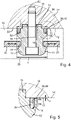
- the clamping element is designed in the form of a clamping bolt 10 .
- the clamping bolt 10 is used to arrange it on a component 12 to be clamped, which is in figure 4 is shown in sections and can be formed, for example, as a workpiece or workpiece carrier. How out figure 4 As becomes clear, the clamping bolt 10 is fastened with a fastening screw 14 which passes through the clamping bolt 10 and is screwed into a thread 16 provided on the component 12 .
- the clamping bolt 10 has a central bore 18 for this purpose.
- the screw 14 or the bore 18 runs along a central axis 20 of the clamping bolt 10.
- the clamping bolt 10 also has a raised, ring-like centering section 15, which is inserted into a ring receptacle provided on the component 12 for the precise positioning of the clamping bolt 10 on the component 12.
- the clamping bolt 10 has a draw-in section 22 running around the central axis 20 .
- Indicated clamping module 26 are provided in the clamping module 26 locking elements 24 which act against the feed section 22.
- the locking elements 24 can be shifted in the radial direction and can be designed as clamping slides or as locking balls. When the locking elements 24 are displaced radially inwards, they interact with the draw-in sections 22 in such a way that the clamping bolt 10 is drawn into the clamping receptacle 28 .
- the component 12 is loaded against a contact surface 30 provided on the clamping module 26 .
- the clamping bolt 10 has a ring-like bearing surface 32 for bearing on the component 12 .
- the bearing surface 32 lies in an in figure 3 and 5 indicated bearing plane 34.
- an annular groove 36 is provided, which surrounds the bearing surface 32 radially on the outside, and an annular web 38, which surrounds the annular groove 36 radially on the outside.
- the annular ridge 38 has a plurality of openings 40 extending through the annular ridge 38 in the radial direction. How from particular figure 2 becomes clear, a total of 16 openings 40 are provided. the Openings 40 are in the form of oblong holes and are open at the edge towards the component 12 . Overall, the ring web 38 thereby forms individual lamellae 42 extending in the axial direction and having a width a and a length a. A total of 16 lamellae 42 are provided, which are each arranged equidistantly around the central axis 20 .
- the lamellae 42 in the longitudinal section running through the central axis 20 have a rectangular section 44 on the side facing the component 12 and a conical section 46 adjoining the rectangular section 44 and tapering in the direction away from the component 12.
- the conical section 46 is also delimited on the side facing away from the rectangular section 44 by a bending edge 48 running transversely to the central axis 20 .
- the design of the lamellae 42 with a rectangular section 44, conical section 46 and bending edge 48 provides a lamella with a favorable geometry, with a type of solid-state joint in the area of the bending edge 48 for elastic flexibility of the lamellae 42 in the radial direction towards the central axis 20 on the lamellae 42 acting forces is provided.
- annular web 38 or the lamellae 42 have an underside 50 facing the component to be clamped, the underside 50 lying in an annular plane 52 running perpendicularly to the central axis 20 .
- the ring plane 52 is spaced apart from the support plane 34 by the dimension x.
- the dimension x is selected in such a way that the individual lamellae 42 can be elastically deformed in the axial direction in such a way that the undersides of the lamellae 50 do not come into physical contact with the component 12 .
- the outer diameter D of the clamping bolt 10 at the level of the rectangular sections 44 or in the ring plane 52 is slightly larger than the inner diameter d of the clamping receptacle 28. This allows the clamping bolt 10 be introduced into the clamping receptacle 28 without play and under prestress.
Landscapes
- Engineering & Computer Science (AREA)
- Mechanical Engineering (AREA)
- Clamps And Clips (AREA)
- Picture Signal Circuits (AREA)
- Wire Bonding (AREA)
- Tone Control, Compression And Expansion, Limiting Amplitude (AREA)
Description
- Die Erfindung betrifft ein Spannelement eines Spannsystems, insbesondere eines Nullpunktspannsystems, wobei das Spannelement zur Anordnung an ein zu spannendes Bauteil und zum Verriegeln an oder in einer Spannaufnahme eines Spannmoduls ausgebildet ist. Das Spannelement ist als Spannbolzen ausgebildet und weist einen um eine Mittelachse verlaufenden Einzugsabschnitt auf, gegen den Verriegelungselemente des Spannmoduls zum Einziehen und Verriegeln des Spannelements wirken. Der Einzugsabschnitt kann insbesondere konusflächig ausgebildet sein. Ferner weist das Spannelement eine Auflagefläche zur Auflage an dem zu spannenden Bauteil auf.
- Aus der
EP 0 858 863 A1 ist ein Spannelement in Form eines Spannbolzens bekannt, der eine die Auflagefläche in radialer Richtung umgebende Ringnut und eine die Ringnut in radialer Richtung umgebenden, in radialer Richtung elastisch nachgiebig ausgebildeten Ringsteg vorsieht. Dadurch, dass der Ringsteg in radialer Richtung elastisch nachgiebig ausgebildet ist, kann eine selbsttätige Zentrierung des Spannbolzens in der Spannaufnahme erfolgen. Ferner können unerwünschte Eigenspannungen im gespannten Bauteil, insbesondere bei Verwendung von mehreren Spannbolzen an einem Bauteil, unterbunden werden. - Bei Nullpunktspannmodulen handelt es sich um Spannmodule, mit denen zu bearbeitende Werkstücke oder Werkstückträger wiederholbar positionsgenau gespannt werden können. Dabei ist denkbar, dass mehrere Spannmodule gemeinsam auf einen Träger, beispielsweise auf einem Spanntisch oder einer Spannplatte, vorgesehen werden, um größere Werkstücke mittels mehreren an dem Werkstück oder an dem Werkstückträger vorgesehenen Spannbolzen zu spannen.
- Spannmodule zur Aufnahme von Spannelementen in Form Spannbolzen oder Spannringen sind beispielsweise aus der
DE 10 2010 010 898 A1 , derEP 1 707 307 A1 oder derDE 10 2010 013 911 A1 bekannt. Bei dem zu spannenden Bauteil kann es sich beispielsweise um ein zu bearbeitendes Werkstück oder um einen Werkstückträger handeln. Die Spannelemente werden dann zum positionsgenauen Spannen im oder am jeweiligen Spannmodul verriegelt. - Ein Spannelement ist aus der
DE 10 2017 119 822 A1 , die zum Stand der Technik nach Art. 54(3) EPÜ gehört, bekannt Diese Druckschrift offenbart ein Spannelement eines Spannsystems, wobei das Spannelement als Spannbolzen ausgebildet ist, und wobei das Spannelement zur Anordnung an ein zu spannendes Bauteil und zum Verriegeln in oder an einer Spannaufnahme eines Spannmoduls ausgebildet ist, mit einem um eine Mittelachse verlaufenden Einzugsabschnitt, gegen den Verriegelungselemente des Spannmoduls zum Einziehen und Verriegeln des Spannelements wirken, mit einer Auflagefläche zur Auflage an dem Bauteil, mit einer die Auflagefläche in radialer Richtung umgebende Ringnut und mit einem die Ringnut in radialer Richtung umgebenden, wenigstens abschnittsweise in radialer Richtung elastisch nachgiebig ausgebildeten Ringsteg , wobei der Ringsteg mehrere sich in radialer Richtung erstreckende Durchbrüche aufweist. - Der Erfindung liegt die Aufgabe zugrunde, ein Spannelement der eingangs genannten Art derart weiterzubilden, dass dieser beim Einführen und Verriegeln zum einen sicher in der Spannaufnahme zentriert wird und zum anderen nicht beschädigt wird. Ferner soll das Spannelement spielfrei verriegelt werden können.
- Diese Aufgabe wird gelöst durch ein Spannelement mit den Merkmalen des Patentanspruchs 1. Im Unterschied zum Stand der Technik gemäß der
EP 0 858 863 A1 sieht das erfindungsgemäße Spannelement folglich vor, dass der Ringsteg mehrere sich in radialer Richtung erstreckende Durchbrüche aufweist. Diese Durchbrüche führen dazu, dass der Ringsteg in radialer Richtung elastisch nachgiebig ausgebildet wird. Je nach Anzahl und Größe der vorzusehenden Durchbrüche kann die elastische Nachgiebigkeit eingestellt werden. Das Vorsehen von Durchbrüchen hat ferner den Vorteil, dass diese auf einfache Art und Weise in den Ringsteg eingebracht werden können. - Die
EP 0 858 863 A1 sieht im Gegensatz dazu einen in radialer Richtung geschlossenen Ringsteg vor. Im Ringsteg selber können gemäß diesem Stand der Technik zwar Sackbohrungen vorgesehen sein, die parallel zur Mittelachse verlaufen. Eine Einstellung der elastischen Nachgiebigkeit mittels den Sacklöchern ist nicht oder nur sehr bedingt möglich. Anders als der Stand der Technik geht die vorliegende Erfindung einen Schritt weiter und öffnet den Ringsteg in radialer Richtung durch Vorsehen der Durchbrüche. Eine elastische Nachgiebigkeit kann hierdurch auf einfache Art und Weise günstig eingestellt werden. - Das Spannelement ist als Spannbolzen ausgebildet. Hier liegen die Ringnut und der Ringsteg bezüglich der Auflagefläche radial außen.
- Vorteilhafterweise sind die Durchbrüche in äquidistanten Winkelabständen um die Mittelachse angeordnet. Es hat sich gezeigt, dass insgesamt 10 bis 20 Durchbrüche und vorzugsweise 16 Durchbrüche vorteilhaft sind.
- Die Durchbrüche können dabei als Rundlöcher, als Ovallöcher und/oder als Langlöcher ausgebildet sein.
- Besonders vorteilhaft ist, wenn die Durchbrüche hin zum Bauteil randoffen ausgebildet sind, so dass die Durchbrüche insbesondere als einseitig offene Langlöcher ausgebildet sind. Der Ringsteg wird dann von einzelnen, sich in axialer Richtung erstreckenden Lamellen gebildet.
- Es ist vorgesehen, dass die Auflagefläche in einer senkrecht zur Mittelachse verlaufenden Auflageebene liegt und dass der Ringsteg, beziehungsweise die Lamellen, eine dem zu spannenden Bauteil zugewandte Unterseite aufweist, die in einer senkrecht zur Mittelachse verlaufenden Ringebene liegt, wobei die Ringebene um ein Maß x, mit x > 0, von der Auflageebene in Richtung weg vom Bauteil beanstandet angeordnet ist. Beim montierten Spannelement liegt folglich die Auflageebene am Bauteil an und die Ringebene ist um das Maß x vom Bauteil beanstandet. Dadurch kann ein ungehindertes elastisches Verformen des Ringstegs beziehungsweise der den Ringsteg bildenden Lamellen gewährleistet werden.
- Das Maß x ist dabei vorteilhafterweise so groß, dass bei elastisch verformten Ringsteg beziehungsweise elastisch verformten Lamellen die Unterseite des Ringstegs beziehungsweise der Lamellen nicht in Berührkontakt mit dem Bauteil kommt.
- Die Durchbrüche zwischen den Lamellen können vorzugsweise als randoffene Langlöcher ausgebildet sein, wobei die Langlöcher dann an der der offenen Seite gegenüberliegenden Seite jeweils einen vorzugsweise entlang einer Kreisbahn verlaufenden Grund aufweisen.
- Vorteilhafterweise sind die Lamellen in radialer Ansicht quadratisch oder im Wesentlichen quadratisch ausgebildet. Es hat sich gezeigt, dass gerade die quadratische Ausbildung der Lamellen mit einer Kantenlänge x zu günstigen elastischen Eigenschaften führt.
- Ferner ist vorteilhaft, wenn die Lamellen im Längsschnitt auf der dem Bauteil zugewandten Seite einen Rechteckabschnitt und einen sich daran anschließenden, sich verjüngenden Konusabschnitt aufweisen. Der Rechteckabschnitt weist im Querschnitt eine rechteckige Kontur auf. Die Mantelfläche des Rechteckabschnitts verläuft dazu parallel oder im Wesentlichen parallel zur gegenüberliegenden, an die Ringnut angrenzenden Fläche. An den Rechteckabschnitt schließt sich dann der sich verjüngende Konusabschnitt an, dessen Mantelfläche sich mit zum Bauteil zunehmendem Abstand verjüngt.
- Weiterhin ist vorteilhaft, wenn der Konusabschnitt auf der dem Rechteckabschnitt abgewandten Seite eine quer zur Mittelachse verlaufende Biegekante aufweist. Dadurch kann eine Art definiertes Festkörpergelenk zur elastischen Verformung der Lamellen bereitgestellt werden.
- Die eingangs genannte Aufgabe wird auch gelöst durch ein zu spannendes Bauteil mit wenigstens einem erfindungsgemäßen Spannelement.
- Die eingangs genannte Aufgabe wird auch gelöst durch ein Spannsystem mit einem zu spannenden Bauteil, welches wenigstens einen erfindungsgemäßen Spannelement vorsieht.
- Weitere Einzelheiten und vorteilhafte Ausgestaltungen der Erfindung sind der nachfolgenden Beschreibung zu entnehmen, anhand derer ein Ausführungsbeispiel der Erfindung näher beschrieben und erläutert ist.
- Es zeigen:
- Figur 1
- ein erstes erfindungsgemäßes Spannelement in isometrischer Ansicht;
- Figur 2
- die Unteransicht des Spannbolzens gemäß
Figur 1 ; - Figur 3
- die Seitenansicht des Spannbolzens gemäß
Figur 1 ; - Figur 4
- einen Längsschnitt durch den Spannbolzen gemäß
Figur 1 ; und - Figur 5
- einen vergrößerte Ausschnitt aus
Figur 4 . - In den
Figuren 1 bis 4 ist eine erfindungsgemäße Ausführungsform der Erfindung gezeigt, bei der das Spannelement in Form eines Spannbolzens 10 ausgebildet ist. Der Spannbolzen 10 dient dabei zur Anordnung an ein zu spannendes Bauteil 12, das inFigur 4 abschnittsweise gezeigt ist und beispielsweise als Werkstück oder Werkstückträger ausgebildet sein kann. Wie ausFigur 4 deutlich wird, dient zur Befestigung des Spannbolzens 10 eine Befestigungsschraube 14, die den Spannbolzen 10 durchgreift und in ein am Bauteil 12 vorgesehenes Gewinde 16 eingeschraubt ist. Der Spannbolzen 10 sieht hierfür eine zentrale Bohrung 18 vor. Die Schraube 14 beziehungsweise die Bohrung 18 verlaufen dabei entlang einer Mittelachse 20 des Spannbolzens 10. Der Spannbolzen 10 weist zudem einen erhabenen, ringartigen Zentrierabschnitt 15 auf, der in eine am Bauteil 12 vorgesehen Ringaufnahme zur positionsgenauen Anordnung des Spannbolzens 10 am Bauteil 12 eingesetzt wird. - Wie aus den
Figuren 1 bis 4 deutlich wird, weist der Spannbolzen 10 einen um die Mittelachse 20 verlaufenden Einzugsabschnitt 22 auf. Zur Verriegelung des Spannbolzens 10 in einem inFigur 4 angedeuteten Spannmodul 26 sind im Spannmodul 26 Verriegelungselemente 24 vorgesehen, die gegen den Einzugsabschnitt 22 wirken. Die Verriegelungselemente 24 können dabei in radialer Richtung verlagert werden und als Spannschieber oder als Verriegelungskugeln ausgebildet sein. Beim Verlagern der Verriegelungselemente 24 nach radial innen wirken diese mit den Einzugsabschnitten 22 derart zusammen, dass der Spannbolzen 10 in die Spannaufnahme 28 eingezogen wird. Durch Verriegelung des Spannbolzens 10 im Spannmodul 26 wird das Bauteil 12 gegen eine am Spannmodul 26 vorgesehene Anlagefläche 30 beaufschlagt. - Wie aus insbesondere den
Figuren 1 bis 3 deutlich wird, weist der Spannbolzen 10 eine ringartige Auflagefläche 32 zur Auflage an dem Bauteil 12 auf. Die Auflagefläche 32 liegt dabei in einer senkrecht zur Mittelachse 20 verlaufenden, inFigur 3 und5 angedeuteten Auflageebene 34. Ferner ist eine Ringnut 36 vorgesehen, die die Auflagefläche 32 radial außen umgibt sowie ein Ringsteg 38, der die Ringnut 36 radial außen umgibt. - Der Ringsteg 38 weist dabei mehrere sich in radialer Richtung durch den Ringsteg 38 hindurch erstreckende Durchbrüche 40 auf. Wie aus insbesondere
Figur 2 deutlich wird, sind insgesamt 16 Durchbrüche 40 vorgesehen. Die Durchbrüche 40 sind als Langlöcher ausgebildet und hin zum Bauteil 12 randoffen ausgebildet. Insgesamt bildet der Ringsteg 38 dadurch einzelne, sich in axialer Richtung erstreckende Lamellen 42 mit einer Breite a und einer Länge a. In Summe sind 16 Lamellen 42 vorgesehen, die jeweils um die Mittelachse 20 herum äquidistant angeordnet sind. - Aus der Vergrößerung gemäß
Figur 5 wird deutlich, dass die Lamellen 42 im durch die Mittelachse 20 verlaufenden Längsschnitt auf der dem Bauteil 12 zugewandten Seite einen Rechteckabschnitt 44 und einen sich an den Rechteckabschnitt 44 anschließenden, sich in Richtung weg vom Bauteil 12 verjüngenden Konusabschnitt 46 aufweisen. Der Konusabschnitt 46 wird ferner auf der dem Rechteckabschnitt 44 abgewandten Seite von einer quer zur Mittelachse 20 verlaufenden Biegekante 48 begrenzt. - Durch die Ausbildung der Lamellen 42 mit Rechteckabschnitt 44, Konusabschnitt 46 und Biegekante 48 wird eine Lamelle mit einer günstigen Geometrie bereitgestellt, wobei im Bereich der Biegekante 48 eine Art Festkörpergelenk zur elastischen Nachgiebigkeit der Lamellen 42 bei in radialer Richtung hin zur Mittelachse 20 auf die Lamellen 42 wirkenden Kräfte bereitgestellt wird.
- Aus
Figur 5 wird ferner deutlich, dass der Ringsteg 38, beziehungsweise die Lamellen 42, eine dem zu spannenden Bauteil zugewandte Unterseite 50 aufweisen, wobei die Unterseite 50 in einer senkrecht zur Mittelachse 20 verlaufenden Ringebene 52 liegt. Wie aus der Vergrößerung gemäßFigur 5 deutlich wird, ist die Ringebene 52 zur Auflageebene 34 um das Maß x beabstandet. Das Maß x ist dabei so gewählt, dass die einzelnen Lamellen 42 in axialer Richtung derart elastisch verformt werden können, dass die Unterseiten der Lamellen 50 nicht mit dem Bauteil 12 in Berührkontakt kommen. - Um eine geeignete Zentrierung des Spannbolzens 10 in der Spannaufnahme 28 zu gewährleisten, ist vorteilhaft, wenn der Außendurchmesser D des Spannbolzens 10 auf Höhe der Rechteckabschnitte 44 beziehungsweise in der Ringebene 52 geringfügig größer ist wie der Innendurchmesser d der Spannaufnahme 28. Dadurch kann der Spannbolzen 10 spielfrei und unter Vorspannung in die Spannaufnahme 28 eingeführt werden.
Claims (10)
- Spannelement (10) eines Spannsystems, insbesondere eines Nullpunktspannsystems, wobei das Spannelement (10) als Spannbolzen (10) ausgebildet ist, und wobei das Spannelement (10) zur Anordnung an ein zu spannendes Bauteil (12) und zum Verriegeln in oder an einer Spannaufnahme (28) eines Spannmoduls (26) ausgebildet ist, mit einem um eine Mittelachse (20) verlaufenden Einzugsabschnitt (22), gegen den Verriegelungselemente (24) des Spannmoduls (26) zum Einziehen und Verriegeln des Spannelements (10) wirken, mit einer Auflagefläche (32) zur Auflage an dem Bauteil (12), mit einer die Auflagefläche (32) in radialer Richtung umgebende Ringnut (36) und mit einem die Ringnut (36) in radialer Richtung umgebenden, wenigstens abschnittsweise in radialer Richtung elastisch nachgiebig ausgebildeten Ringsteg (38), wobei der Ringsteg (38) mehrere sich in radialer Richtung erstreckende Durchbrüche (40) aufweist, wobei die Auflagefläche (32) in einer senkrecht zur Mittelachse verlaufenden Auflageebene (34) liegt, und wobei der Ringsteg (38) eine dem zu spannenden Bauteil (12) zugewandte Unterseite aufweist, die in einer senkrecht zur Mittelachse verlaufenden Ringebene (52) liegt, wobei die Ringebene (52) um ein Maß x, mit x > 0, von der Auflageebene (34) in Richtung weg vom Bauteil (12) beabstandet angeordnet ist.
- Spannelement (10) nach Anspruch 1, dadurch gekennzeichnet, dass die Durchbrüche (40) in äquidistanten Winkelabständen um die Mittelachse (20) angeordnet sind.
- Spannelement (10) nach Anspruch 1 oder 2, dadurch gekennzeichnet, dass die Durchbrüche (40) als Rundlöcher, als Ovallöcher oder als Langlöcher ausgebildet sind.
- Spannelement (10) nach Anspruch 1, 2 oder 3, dadurch gekennzeichnet, dass die Durchbrüche (40) hin zum Bauteil randoffen ausgebildet sind, so dass der Ringsteg (38) von einzelnen, sich in axialer Richtung erstreckenden Lamellen (42) gebildet wird.
- Spannelement (10) nach Anspruch 4, dadurch gekennzeichnet, dass die Lamellen (42) in radialer Ansicht quadratisch oder im Wesentlichen quadratisch ausgebildet sind.
- Spannelement (10) nach Anspruch 4 oder 5, dadurch gekennzeichnet, dass die Lamellen (42) im Längsschnitt auf der dem Bauteil zugewandten Seite einen Rechteckabschnitt (44) und einen sich daran anschließenden, sich verjüngen Konusabschnitt (46) aufweisen.
- Spannelement (10) nach Anspruch 6, dadurch gekennzeichnet, dass der Konusabschnitt (46) auf der dem Rechteckabschnitt (44) abgewandten Seite eine quer zur Mittelachse verlaufende Biegekante (48) aufweist.
- Spannelement (10) nach einem der vorangehenden Ansprüche, dadurch gekennzeichnet, dass das Maß x so gewählt ist, dass bei elastisch verformtem Ringsteg (38) die Unterseite (50) des Ringstegs (38) nicht in Berührungskontakt mit dem Bauteil (12) kommt.
- Zu spannendes Bauteil (12) mit wenigstens einem Spannelement (10) nach wenigstens einem der vorhergehenden Ansprüche.
- Spannsystem mit einem zu spannenden Bauteil (12) mit wenigstens einem und vorzugsweise zwei oder mehr Spannelemente (10) gemäß einem der Ansprüche 1 bis 6, und mit wenigstens einem und vorzugsweise zwei oder mehr Spannmodulen (26) zur Aufnahme und Verriegelung des wenigstens einen Spannelements (10).
Applications Claiming Priority (1)
| Application Number | Priority Date | Filing Date | Title |
|---|---|---|---|
| DE102018111618.7A DE102018111618A1 (de) | 2018-05-15 | 2018-05-15 | Spannelement eines Spannsystems, insbesondere eines Nullpunktspannsystems, und Spannsystem |
Publications (2)
| Publication Number | Publication Date |
|---|---|
| EP3569352A1 EP3569352A1 (de) | 2019-11-20 |
| EP3569352B1 true EP3569352B1 (de) | 2023-01-18 |
Family
ID=65818355
Family Applications (1)
| Application Number | Title | Priority Date | Filing Date |
|---|---|---|---|
| EP19163493.0A Active EP3569352B1 (de) | 2018-05-15 | 2019-03-18 | Spannelement eines spannsystems, insbesondere eines nullpunktspannsystems, und spannsystem |
Country Status (3)
| Country | Link |
|---|---|
| EP (1) | EP3569352B1 (de) |
| DE (1) | DE102018111618A1 (de) |
| ES (1) | ES2938984T3 (de) |
Families Citing this family (5)
| Publication number | Priority date | Publication date | Assignee | Title |
|---|---|---|---|---|
| DE102019133760B4 (de) * | 2019-12-10 | 2023-05-04 | Innoclamp GmbH | Modulares Spannsystem und Verfahren |
| CN111571309A (zh) * | 2020-07-01 | 2020-08-25 | 上海工具厂有限公司 | 用于集成加工过程监控的零点定位夹具 |
| EP4082714A1 (de) * | 2021-04-27 | 2022-11-02 | Officina Meccanica Lombarda S.r.l. | Stift zum verriegeln von werkstücken, insbesondere von formen zur bearbeitung auf werkzeugmaschinen |
| DE102021118265A1 (de) * | 2021-07-14 | 2023-01-19 | Endress+Hauser Flowtec Ag | Feldgerät mit einem Sensor zur Erfassung einer physikalischen Messgröße und Klemmelement zur Befestigung eines Gehäuses eines Feldgeräts an einem Sensorhals |
| CN114799989B (zh) * | 2022-05-28 | 2023-03-31 | 苏州新火花机床有限公司 | 零点定位装置 |
Family Cites Families (8)
| Publication number | Priority date | Publication date | Assignee | Title |
|---|---|---|---|---|
| DE19705685C1 (de) * | 1997-02-14 | 1998-03-26 | Emil Stark | Spielfreier, vorgespannter Einzugsnippel für ein Schnellspannsystem |
| JP4762448B2 (ja) * | 2001-07-24 | 2011-08-31 | パスカルエンジニアリング株式会社 | ワークパレット位置決め固定装置 |
| ATE437724T1 (de) * | 2005-03-31 | 2009-08-15 | Schunk Gmbh & Co Kg | Schnellspannsystem |
| JP5357058B2 (ja) * | 2008-01-28 | 2013-12-04 | パスカルエンジニアリング株式会社 | ワークパレット位置決め固定装置 |
| DE102010010898C5 (de) * | 2010-03-05 | 2017-04-13 | Schunk Gmbh & Co. Kg | Nullpunktspannsystem |
| DE102010013911B4 (de) * | 2010-04-01 | 2013-07-25 | Schunk Gmbh & Co. Kg Spann- Und Greiftechnik | Spannmodul, insbesondere Nullpunktspannmodul |
| DE102010013912A1 (de) * | 2010-04-01 | 2011-10-06 | Schunk Gmbh & Co. Kg Spann- Und Greiftechnik | Spannbolzen zum Einspannen in ein Spannmodul und Spannsystem |
| DE102017119822B4 (de) * | 2017-08-29 | 2024-02-01 | Zeroclamp Gmbh | Doppelfunktion eines Zentrierkonus für eine Aufnahme einer Spannvorrichtung und Spannvorrichtung |
-
2018
- 2018-05-15 DE DE102018111618.7A patent/DE102018111618A1/de not_active Ceased
-
2019
- 2019-03-18 EP EP19163493.0A patent/EP3569352B1/de active Active
- 2019-03-18 ES ES19163493T patent/ES2938984T3/es active Active
Also Published As
| Publication number | Publication date |
|---|---|
| ES2938984T3 (es) | 2023-04-18 |
| DE102018111618A1 (de) | 2019-11-21 |
| EP3569352A1 (de) | 2019-11-20 |
Similar Documents
| Publication | Publication Date | Title |
|---|---|---|
| EP2371479B1 (de) | Zentrierelement, Spannbolzen, Trägerbauteil und Spannsystem | |
| EP3569352A1 (de) | Spannelement eines spannsystems, insbesondere eines nullpunktspannsystems, und spannsystem | |
| EP2357058B1 (de) | Spannsystem, insbesondere Nullpunktspannsystem | |
| EP3219435B1 (de) | Einzugsspannelement, insbesondere einzugsspannbolzen oder einzugsspannring, und zugehöriges spannsystem | |
| EP2759370B1 (de) | Spannsystem, insbesondere Nullpunktspannsystem, und Ausgleichspannbolzen | |
| EP3308065B1 (de) | Schelle | |
| DE102017119822B4 (de) | Doppelfunktion eines Zentrierkonus für eine Aufnahme einer Spannvorrichtung und Spannvorrichtung | |
| EP1704957B1 (de) | Kupplungsvorrichtung mit elastischen Bereichen zur X-Y-Ausrichtung | |
| EP3330196B1 (de) | Vorrichtung zur aufnahme von gegenständen und zugehöriger verbindungskörper | |
| WO2021099319A1 (de) | Fliessläppvorrichtung zum glätten einer fläche eines werkstückes | |
| DE102013110671B4 (de) | Verschleißkörper zur Aufnahme einer Doppelschnecke zur Extrusion von schmelzfähigem Material | |
| EP2766137B1 (de) | Werkzeugsystem zur spanabhebenden bearbeitung eines werkstücks | |
| EP3395496B1 (de) | Spanneinheit mit spannmodul und spannsystem | |
| DE102013219954A1 (de) | Spannsystem, insbesondere Nullpunktspannsystem | |
| EP1551092B1 (de) | Schutzkappe, insbesondere für einen Drehstromgenerator | |
| EP3186527B1 (de) | Knickfedereinrichtung | |
| EP3366417B1 (de) | Spannbolzen eines nullpunktspannsystems | |
| EP0858863A1 (de) | Spielfreier, vorgespannter Einzugsnippel für ein Schnellspannsystem | |
| EP1515172B1 (de) | Spannungsarme Optikfassung | |
| EP3241934A1 (de) | Textilwerkzeugmodul und textilmaschine mit einem textilwerkzeugmodul | |
| EP0849478B1 (de) | Magazinband für Befestigungselemente | |
| EP4330559B1 (de) | Befestigungsmittelhalter, montagesystem und verfahren zum montieren eines befestigungsmittels | |
| EP4163526B1 (de) | Manschettenartiges befestigungselement sowie zentrierelement | |
| DE29915750U1 (de) | Spanneinrichtung zum Befestigen von Erodierelektroden an den Halteelementen von Fräsmaschinen und Erodiermaschinen | |
| DE202009011365U1 (de) | Kabelhalter mit Zugentlastung |
Legal Events
| Date | Code | Title | Description |
|---|---|---|---|
| PUAI | Public reference made under article 153(3) epc to a published international application that has entered the european phase |
Free format text: ORIGINAL CODE: 0009012 |
|
| STAA | Information on the status of an ep patent application or granted ep patent |
Free format text: STATUS: THE APPLICATION HAS BEEN PUBLISHED |
|
| AK | Designated contracting states |
Kind code of ref document: A1 Designated state(s): AL AT BE BG CH CY CZ DE DK EE ES FI FR GB GR HR HU IE IS IT LI LT LU LV MC MK MT NL NO PL PT RO RS SE SI SK SM TR |
|
| AX | Request for extension of the european patent |
Extension state: BA ME |
|
| STAA | Information on the status of an ep patent application or granted ep patent |
Free format text: STATUS: REQUEST FOR EXAMINATION WAS MADE |
|
| 17P | Request for examination filed |
Effective date: 20200518 |
|
| RBV | Designated contracting states (corrected) |
Designated state(s): AL AT BE BG CH CY CZ DE DK EE ES FI FR GB GR HR HU IE IS IT LI LT LU LV MC MK MT NL NO PL PT RO RS SE SI SK SM TR |
|
| GRAP | Despatch of communication of intention to grant a patent |
Free format text: ORIGINAL CODE: EPIDOSNIGR1 |
|
| STAA | Information on the status of an ep patent application or granted ep patent |
Free format text: STATUS: GRANT OF PATENT IS INTENDED |
|
| INTG | Intention to grant announced |
Effective date: 20220803 |
|
| GRAS | Grant fee paid |
Free format text: ORIGINAL CODE: EPIDOSNIGR3 |
|
| GRAA | (expected) grant |
Free format text: ORIGINAL CODE: 0009210 |
|
| STAA | Information on the status of an ep patent application or granted ep patent |
Free format text: STATUS: THE PATENT HAS BEEN GRANTED |
|
| AK | Designated contracting states |
Kind code of ref document: B1 Designated state(s): AL AT BE BG CH CY CZ DE DK EE ES FI FR GB GR HR HU IE IS IT LI LT LU LV MC MK MT NL NO PL PT RO RS SE SI SK SM TR |
|
| REG | Reference to a national code |
Ref country code: GB Ref legal event code: FG4D Free format text: NOT ENGLISH |
|
| REG | Reference to a national code |
Ref country code: DE Ref legal event code: R096 Ref document number: 502019006803 Country of ref document: DE |
|
| REG | Reference to a national code |
Ref country code: CH Ref legal event code: EP |
|
| REG | Reference to a national code |
Ref country code: AT Ref legal event code: REF Ref document number: 1544410 Country of ref document: AT Kind code of ref document: T Effective date: 20230215 Ref country code: IE Ref legal event code: FG4D Free format text: LANGUAGE OF EP DOCUMENT: GERMAN |
|
| REG | Reference to a national code |
Ref country code: ES Ref legal event code: FG2A Ref document number: 2938984 Country of ref document: ES Kind code of ref document: T3 Effective date: 20230418 |
|
| REG | Reference to a national code |
Ref country code: LT Ref legal event code: MG9D |
|
| REG | Reference to a national code |
Ref country code: NL Ref legal event code: MP Effective date: 20230118 |
|
| PG25 | Lapsed in a contracting state [announced via postgrant information from national office to epo] |
Ref country code: NL Free format text: LAPSE BECAUSE OF FAILURE TO SUBMIT A TRANSLATION OF THE DESCRIPTION OR TO PAY THE FEE WITHIN THE PRESCRIBED TIME-LIMIT Effective date: 20230118 |
|
| PG25 | Lapsed in a contracting state [announced via postgrant information from national office to epo] |
Ref country code: RS Free format text: LAPSE BECAUSE OF FAILURE TO SUBMIT A TRANSLATION OF THE DESCRIPTION OR TO PAY THE FEE WITHIN THE PRESCRIBED TIME-LIMIT Effective date: 20230118 Ref country code: PT Free format text: LAPSE BECAUSE OF FAILURE TO SUBMIT A TRANSLATION OF THE DESCRIPTION OR TO PAY THE FEE WITHIN THE PRESCRIBED TIME-LIMIT Effective date: 20230518 Ref country code: NO Free format text: LAPSE BECAUSE OF FAILURE TO SUBMIT A TRANSLATION OF THE DESCRIPTION OR TO PAY THE FEE WITHIN THE PRESCRIBED TIME-LIMIT Effective date: 20230418 Ref country code: LV Free format text: LAPSE BECAUSE OF FAILURE TO SUBMIT A TRANSLATION OF THE DESCRIPTION OR TO PAY THE FEE WITHIN THE PRESCRIBED TIME-LIMIT Effective date: 20230118 Ref country code: LT Free format text: LAPSE BECAUSE OF FAILURE TO SUBMIT A TRANSLATION OF THE DESCRIPTION OR TO PAY THE FEE WITHIN THE PRESCRIBED TIME-LIMIT Effective date: 20230118 Ref country code: HR Free format text: LAPSE BECAUSE OF FAILURE TO SUBMIT A TRANSLATION OF THE DESCRIPTION OR TO PAY THE FEE WITHIN THE PRESCRIBED TIME-LIMIT Effective date: 20230118 |
|
| P01 | Opt-out of the competence of the unified patent court (upc) registered |
Effective date: 20230628 |
|
| PG25 | Lapsed in a contracting state [announced via postgrant information from national office to epo] |
Ref country code: SE Free format text: LAPSE BECAUSE OF FAILURE TO SUBMIT A TRANSLATION OF THE DESCRIPTION OR TO PAY THE FEE WITHIN THE PRESCRIBED TIME-LIMIT Effective date: 20230118 Ref country code: PL Free format text: LAPSE BECAUSE OF FAILURE TO SUBMIT A TRANSLATION OF THE DESCRIPTION OR TO PAY THE FEE WITHIN THE PRESCRIBED TIME-LIMIT Effective date: 20230118 Ref country code: IS Free format text: LAPSE BECAUSE OF FAILURE TO SUBMIT A TRANSLATION OF THE DESCRIPTION OR TO PAY THE FEE WITHIN THE PRESCRIBED TIME-LIMIT Effective date: 20230518 Ref country code: GR Free format text: LAPSE BECAUSE OF FAILURE TO SUBMIT A TRANSLATION OF THE DESCRIPTION OR TO PAY THE FEE WITHIN THE PRESCRIBED TIME-LIMIT Effective date: 20230419 Ref country code: FI Free format text: LAPSE BECAUSE OF FAILURE TO SUBMIT A TRANSLATION OF THE DESCRIPTION OR TO PAY THE FEE WITHIN THE PRESCRIBED TIME-LIMIT Effective date: 20230118 |
|
| REG | Reference to a national code |
Ref country code: DE Ref legal event code: R097 Ref document number: 502019006803 Country of ref document: DE |
|
| PG25 | Lapsed in a contracting state [announced via postgrant information from national office to epo] |
Ref country code: SM Free format text: LAPSE BECAUSE OF FAILURE TO SUBMIT A TRANSLATION OF THE DESCRIPTION OR TO PAY THE FEE WITHIN THE PRESCRIBED TIME-LIMIT Effective date: 20230118 Ref country code: RO Free format text: LAPSE BECAUSE OF FAILURE TO SUBMIT A TRANSLATION OF THE DESCRIPTION OR TO PAY THE FEE WITHIN THE PRESCRIBED TIME-LIMIT Effective date: 20230118 Ref country code: MC Free format text: LAPSE BECAUSE OF FAILURE TO SUBMIT A TRANSLATION OF THE DESCRIPTION OR TO PAY THE FEE WITHIN THE PRESCRIBED TIME-LIMIT Effective date: 20230118 Ref country code: EE Free format text: LAPSE BECAUSE OF FAILURE TO SUBMIT A TRANSLATION OF THE DESCRIPTION OR TO PAY THE FEE WITHIN THE PRESCRIBED TIME-LIMIT Effective date: 20230118 Ref country code: DK Free format text: LAPSE BECAUSE OF FAILURE TO SUBMIT A TRANSLATION OF THE DESCRIPTION OR TO PAY THE FEE WITHIN THE PRESCRIBED TIME-LIMIT Effective date: 20230118 Ref country code: CZ Free format text: LAPSE BECAUSE OF FAILURE TO SUBMIT A TRANSLATION OF THE DESCRIPTION OR TO PAY THE FEE WITHIN THE PRESCRIBED TIME-LIMIT Effective date: 20230118 |
|
| PLBE | No opposition filed within time limit |
Free format text: ORIGINAL CODE: 0009261 |
|
| STAA | Information on the status of an ep patent application or granted ep patent |
Free format text: STATUS: NO OPPOSITION FILED WITHIN TIME LIMIT |
|
| PG25 | Lapsed in a contracting state [announced via postgrant information from national office to epo] |
Ref country code: SK Free format text: LAPSE BECAUSE OF FAILURE TO SUBMIT A TRANSLATION OF THE DESCRIPTION OR TO PAY THE FEE WITHIN THE PRESCRIBED TIME-LIMIT Effective date: 20230118 |
|
| REG | Reference to a national code |
Ref country code: BE Ref legal event code: MM Effective date: 20230331 |
|
| 26N | No opposition filed |
Effective date: 20231019 |
|
| GBPC | Gb: european patent ceased through non-payment of renewal fee |
Effective date: 20230418 |
|
| PG25 | Lapsed in a contracting state [announced via postgrant information from national office to epo] |
Ref country code: LU Free format text: LAPSE BECAUSE OF NON-PAYMENT OF DUE FEES Effective date: 20230318 |
|
| REG | Reference to a national code |
Ref country code: IE Ref legal event code: MM4A |
|
| PG25 | Lapsed in a contracting state [announced via postgrant information from national office to epo] |
Ref country code: GB Free format text: LAPSE BECAUSE OF NON-PAYMENT OF DUE FEES Effective date: 20230418 |
|
| PG25 | Lapsed in a contracting state [announced via postgrant information from national office to epo] |
Ref country code: SI Free format text: LAPSE BECAUSE OF FAILURE TO SUBMIT A TRANSLATION OF THE DESCRIPTION OR TO PAY THE FEE WITHIN THE PRESCRIBED TIME-LIMIT Effective date: 20230118 Ref country code: IE Free format text: LAPSE BECAUSE OF NON-PAYMENT OF DUE FEES Effective date: 20230318 Ref country code: GB Free format text: LAPSE BECAUSE OF NON-PAYMENT OF DUE FEES Effective date: 20230418 |
|
| PG25 | Lapsed in a contracting state [announced via postgrant information from national office to epo] |
Ref country code: BE Free format text: LAPSE BECAUSE OF NON-PAYMENT OF DUE FEES Effective date: 20230331 |
|
| PG25 | Lapsed in a contracting state [announced via postgrant information from national office to epo] |
Ref country code: BG Free format text: LAPSE BECAUSE OF FAILURE TO SUBMIT A TRANSLATION OF THE DESCRIPTION OR TO PAY THE FEE WITHIN THE PRESCRIBED TIME-LIMIT Effective date: 20230118 |
|
| PG25 | Lapsed in a contracting state [announced via postgrant information from national office to epo] |
Ref country code: BG Free format text: LAPSE BECAUSE OF FAILURE TO SUBMIT A TRANSLATION OF THE DESCRIPTION OR TO PAY THE FEE WITHIN THE PRESCRIBED TIME-LIMIT Effective date: 20230118 |
|
| REG | Reference to a national code |
Ref country code: AT Ref legal event code: MM01 Ref document number: 1544410 Country of ref document: AT Kind code of ref document: T Effective date: 20240318 |
|
| PGFP | Annual fee paid to national office [announced via postgrant information from national office to epo] |
Ref country code: ES Payment date: 20250429 Year of fee payment: 7 |
|
| PGFP | Annual fee paid to national office [announced via postgrant information from national office to epo] |
Ref country code: CH Payment date: 20250401 Year of fee payment: 7 |
|
| PG25 | Lapsed in a contracting state [announced via postgrant information from national office to epo] |
Ref country code: AT Free format text: LAPSE BECAUSE OF NON-PAYMENT OF DUE FEES Effective date: 20240318 |
|
| PG25 | Lapsed in a contracting state [announced via postgrant information from national office to epo] |
Ref country code: CY Free format text: LAPSE BECAUSE OF FAILURE TO SUBMIT A TRANSLATION OF THE DESCRIPTION OR TO PAY THE FEE WITHIN THE PRESCRIBED TIME-LIMIT; INVALID AB INITIO Effective date: 20190318 |
|
| PG25 | Lapsed in a contracting state [announced via postgrant information from national office to epo] |
Ref country code: HU Free format text: LAPSE BECAUSE OF FAILURE TO SUBMIT A TRANSLATION OF THE DESCRIPTION OR TO PAY THE FEE WITHIN THE PRESCRIBED TIME-LIMIT; INVALID AB INITIO Effective date: 20190318 |
|
| PG25 | Lapsed in a contracting state [announced via postgrant information from national office to epo] |
Ref country code: TR Free format text: LAPSE BECAUSE OF FAILURE TO SUBMIT A TRANSLATION OF THE DESCRIPTION OR TO PAY THE FEE WITHIN THE PRESCRIBED TIME-LIMIT Effective date: 20230118 |
|
| REG | Reference to a national code |
Ref country code: CH Ref legal event code: U11 Free format text: ST27 STATUS EVENT CODE: U-0-0-U10-U11 (AS PROVIDED BY THE NATIONAL OFFICE) Effective date: 20260401 |
|
| PGFP | Annual fee paid to national office [announced via postgrant information from national office to epo] |
Ref country code: DE Payment date: 20260319 Year of fee payment: 8 |
|
| PGFP | Annual fee paid to national office [announced via postgrant information from national office to epo] |
Ref country code: AT Payment date: 20260410 Year of fee payment: 5 |
|
| PGFP | Annual fee paid to national office [announced via postgrant information from national office to epo] |
Ref country code: IT Payment date: 20260324 Year of fee payment: 8 |
|
| PGFP | Annual fee paid to national office [announced via postgrant information from national office to epo] |
Ref country code: FR Payment date: 20260320 Year of fee payment: 8 |