EP1515172B1 - Monture optique à faible contrainte - Google Patents
Monture optique à faible contrainte Download PDFInfo
- Publication number
- EP1515172B1 EP1515172B1 EP04021071A EP04021071A EP1515172B1 EP 1515172 B1 EP1515172 B1 EP 1515172B1 EP 04021071 A EP04021071 A EP 04021071A EP 04021071 A EP04021071 A EP 04021071A EP 1515172 B1 EP1515172 B1 EP 1515172B1
- Authority
- EP
- European Patent Office
- Prior art keywords
- ring
- point spring
- optics
- spring ring
- mounting ring
- Prior art date
- Legal status (The legal status is an assumption and is not a legal conclusion. Google has not performed a legal analysis and makes no representation as to the accuracy of the status listed.)
- Active
Links
- 230000003287 optical effect Effects 0.000 title claims abstract description 59
- 230000002093 peripheral effect Effects 0.000 claims description 4
- 230000000694 effects Effects 0.000 description 5
- 238000005452 bending Methods 0.000 description 3
- 230000005855 radiation Effects 0.000 description 3
- 230000002950 deficient Effects 0.000 description 2
- 239000000463 material Substances 0.000 description 2
- 210000002105 tongue Anatomy 0.000 description 2
- 229910001369 Brass Inorganic materials 0.000 description 1
- 229910000831 Steel Inorganic materials 0.000 description 1
- 239000000853 adhesive Substances 0.000 description 1
- 230000001070 adhesive effect Effects 0.000 description 1
- 239000010951 brass Substances 0.000 description 1
- 230000001419 dependent effect Effects 0.000 description 1
- 210000003746 feather Anatomy 0.000 description 1
- 238000009434 installation Methods 0.000 description 1
- 238000004377 microelectronic Methods 0.000 description 1
- 239000011368 organic material Substances 0.000 description 1
- 230000008439 repair process Effects 0.000 description 1
- 125000006850 spacer group Chemical group 0.000 description 1
- 239000010959 steel Substances 0.000 description 1
- 230000007704 transition Effects 0.000 description 1
Images
Classifications
-
- G—PHYSICS
- G02—OPTICS
- G02B—OPTICAL ELEMENTS, SYSTEMS OR APPARATUS
- G02B7/00—Mountings, adjusting means, or light-tight connections, for optical elements
- G02B7/02—Mountings, adjusting means, or light-tight connections, for optical elements for lenses
- G02B7/026—Mountings, adjusting means, or light-tight connections, for optical elements for lenses using retaining rings or springs
Definitions
- the invention relates to a low-tension optical socket with a mounting ring whose inner surface serves to receive an optical part, which is thus fixed in a radial direction, wherein the orientation of the optical part is determined in an axial direction by a support surface, with respect to the inner circumferential surface opposing the radial direction so as to abut on an edge of a first optical surface of the optical part and in which a three-point spring ring fixes the optical part in the axial direction by abutting three springs of the three-point spring ring on an edge of a second optical surface ,
- Such an optical socket is known from DE 75 37 569 U1.
- a lens is inserted in a socket. In the radial direction, the lens is fixed by the inner circumferential surface of the socket. In the axial direction, the position of the lens on one side is determined by a support surface whose diameter is smaller than the diameter of the lens. From the other side, the lens is fixed by a spring ring against the contact surface. The spring ring is supported against another lens.
- a spacer ring which is screwed against a fixed stop, determines the air gap between the two lenses over the deflection of the spring ring. Between the two lenses is generated by the spring ring backlash.
- the spring ring is formed in one case as a spring washer with at least three resiliently protruding from the disk surface tongues.
- the spring ring is formed as a wave spring with at least three circumferentially distributed waves.
- DE 101 39 805 C1 and DE 100 43 344 A1 describe a low-tension lens frame, which uses a milled into the peripheral surface of the lens annular groove, engage in the three supporting elements. Only the notch stresses generated in the production of the annular groove allow the solution for use of the lens for high-performance systems, which in particular at wavelengths in the UV range as not suitable.
- the invention is based on the object to provide a new low-voltage optical socket.
- the pressure force of the three-point spring ring should be independent of other requirements adjustable or predetermined only by the dimensioning of the parts.
- One or more optical parts of a system should be secured individually, each with a three-point spring washer.
- the overall height in the axial direction should be minimized. In this case, a simple disassembly of complex optical systems is guaranteed, so that repairs of defective optical parts are comparatively easy to carry out.
- the object is achieved by an optical socket of the type mentioned by the characterizing features of claim 1.
- the dependent claims 2 to 8 are advantageous embodiments of claim 1.
- the support surface of the mounting ring has three segments, which are distributed relative to the circumference of the inner circumferential surface and rest on the edge of the first optical surface of the optical part.
- the three-point spring ring is connected to the mounting ring so that in each case a segment-shaped pressure surface of the three springs of the three-point spring ring of the radial direction protrudes only to the extent that it is only in the surface region which faces a support surface of the mounting ring in the axial direction on the Edge of the second optical surface of the optical part suppressed.
- the three-point spring ring has three springs forming segment-shaped pressure surfaces, which press only on the surface areas which are opposite to the bearing surfaces, on the edge of the second optical surface of the optical part.
- a selective introduction of force is created, which acts only on the opposite bearing surfaces of the mounting ring.
- the holding forces are distributed symmetrically and adjustable.
- the opposite force attack reduces the deformation of the optical part to a minimum.
- the easy disassembly of the socket allows easy replacement of defective optical parts.
- a low-voltage mounting of the optical parts is in particular in optical units, where it depends on high resolution and work with short wavelengths required (eg for applications in the microelectronics industry).
- the optical functional surfaces are subject to high tolerance requirements for deformation in order to ensure the optical performance of the systems.
- the inventive solution only materials are used, which are resistant to the aggressive radiation, such as steel, brass.
- organic materials such as adhesives are dispensed with.
- the optical socket has a comparatively low height, which corresponds approximately to the thickness of the optical part. So even the smallest air gaps between several successive optical parts can be realized.
- the optical socket also has a comparatively small radial extent, since the springs have only a small footprint.
- the three-point spring ring is in the unobstructed, de-energized state preferably flat, with mutually parallel annular surfaces. This ensures a minimum assembly height of the socket in the axial direction. Such a part is also particularly inexpensive to produce.
- the three-point spring washer is comparatively thin (ratio of thickness to diameter is on the order of 1: 100), so that small spring forces come into effect.
- the three-point spring ring is used exclusively for fixing the optics in the mounting ring. The orientation of the optics can be adjusted by adjusting the Lampholder after the optical axis of the optical part done when the required centering accuracy makes this required.
- An advantageous embodiment undergoes the three-point spring ring characterized in that it has three recesses in its annular surface, which divide the annular surface into four areas, with an outer region of the attachment of the three-point spring ring with the mounting ring and three areas near the center serves as two-armed springs are formed, which have an equal spring stiffness and only a part of the springs protrude only so far in the direction of the axis of the optical part that they press on the edge of the optical surface of the optical part.
- the outer area is used to attach the three-point spring ring with the mounting ring and ensures in the assembled state for the bias of the springs.
- These springs are particularly suitable because they are claimed both as a bending spring and as a torsion spring.
- each of the recesses is mirror-symmetrical.
- the torsion axes of each of the springs are arranged at an equal distance a and at an equal angle ⁇ relative to the axis of symmetry.
- Each of the springs thus receives defined properties.
- the distance a corresponds approximately to the diameter of the optical part to be taken.
- a further advantageous embodiment is given by the fact that the recesses have a dumbbell-shaped cross-section. Such a shape avoids sharp transitions and thus notch stresses, and creates separate defined spring elements. When mounting the parts indefinite bends are safely avoided.
- Another advantageous feature is that the segments of the bearing surfaces are arranged at an angle of 120 ° and the three-point spring ring has a 120 ° pitch corresponding symmetry.
- the three-point spring ring has three holes for attachment.
- the three-point spring washer is screwed to the mounting ring by means of three screws.
- the holes are designed as conical countersunk holes.
- the screws are cylinder head bolts. The tightening force of the screws can be monitored during screwing by means of a torque wrench, so that each of the springs is biased defined and act precisely measured forces on the optical part.
- Another embodiment for fixing the three-point spring ring is to fasten it by means of a snap ring, which engages in a groove which is introduced into a cylindrical surface of the mounting ring.
- the spring ring is pressed against a contact surface of the mounting ring and the holding forces for the optical part are determined by the dimensioning of the three-point spring ring.
- This alternative to the screw is cheaper.
- other types of attachment can be used, such as a Vorschraubring, rivets or a snap-in connection.
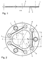
- Figures 1 and 2 show the three-point spring ring 1 in two views. Essential and evident is the complete 120 ° symmetry of the structures introduced into the three-point spring ring 1: spring 2, pressure surface 3, opening 4, countersunk holes 7, recesses 8. First, the three-point spring ring in the center of the free opening 4 for the unimpeded incidence of radiation on an optical part.
- Each of the springs 2 is formed by a dumbbell-shaped recess 8 of the spring ring. This design provides torsion axes 5 and 5 'that do not coincide with the axis of the bend 6.
- Each spring 2 acts as a spiral spring and as a torsion spring.
- Each of the springs 2 has a pressure surface 3, whose radius r is smaller than half the diameter of an optical part (denoted by the reference numeral 19 in FIG. 5). The optical part is touched only with the printing surfaces 3.
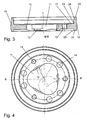
- Figures 3 and 4 show the mounting ring in two views.
- the mounting ring 10 also has a free opening 11 for the free entry of radiation.
- the radial version of the optical part is free of play, but without pressing in an inner lateral surface 15.
- the inner lateral surface 15 has on one side of the lens diameter protruding bearing surfaces 12. These serve as an axial stop for the optical part, which acts in only three points.
- the bearing surfaces 12 have the radius r, which corresponds to that of the springs 2.
- Threaded holes 13 are used for attachment and adjustment of the clamping force of the three-point spring ring 1 by screws.
- the socket 10 further has an outer fit 16, which is made by adjusting the rotation of the position of the optical part in the mounted mounting ring.
- the top surfaces 21 and 22 are made according to the position of the optical part in the mounted mounting ring, so that in a stacking several identical mounting rings air gaps of the optical parts and the centering state are maintained with high accuracy.
- the mounting ring further has cylindrical surfaces 23, 24 and 25.
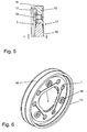
- Figure 5 shows a seized optical part 19 in section.
- the attachment of the three-point spring ring 1 is carried out with countersunk screws 18.
- the pressure surface 3 of the spring 2 presses against the stop surface 12 on the optical part 19th
- the three-point spring ring is not pressed against a stop surface 17 in the example. Rather, there is a sensitive adjustment of the cylinder head bolts 18 with a torque wrench.
- Figure 6 shows the captured optical part of FIG. 5 in a perspective view.
- the strict 120 ° symmetry and the comparatively low height in the axial direction can be seen.
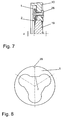
- FIG. 7 shows an alternative embodiment of the invention dispensing with the three cylinder head bolts.
- the three-point spring ring 1 is connected here with three rivets 26.
- Figure 8 shows a three-point spring ring 1 with a design of the springs 2 as a simple leaf springs (effect only as a spiral spring).
- the attachment of the three-point spring ring 1 is provided with a snap ring, which is inserted into a groove of a cylindrical surface of the mounting ring 10.
- Another version uses a Vorschraubring which is screwed into the socket ring and the Three-point spring washer biases (not shown).
- the three-point spring ring has a notch 28, which corresponds to a corresponding mark in the socket ring, so as to ensure that the pressure surfaces 3 are exactly opposite the support surfaces 12 (see also Figure 3 and Figure 4 ).
Landscapes
- Physics & Mathematics (AREA)
- General Physics & Mathematics (AREA)
- Optics & Photonics (AREA)
- Mounting And Adjusting Of Optical Elements (AREA)
- Bolts, Nuts, And Washers (AREA)
- Gyroscopes (AREA)
- Registering, Tensioning, Guiding Webs, And Rollers Therefor (AREA)
- Photoreceptors In Electrophotography (AREA)
- Lens Barrels (AREA)
- Springs (AREA)
Claims (8)
- Monture optique à faible contrainte comprenant une bague de monture (10), dont la surface d'enveloppe (15) intérieure sert au logement d'une partie optique (19), qui doit donc être fixée dans une direction (r) radiale, l'orientation de la partie optique (19) dans une direction (z) axiale étant déterminée par une surface d'appui (12), qui dépasse de la surface d'enveloppe interne (15) vers l'intérieur de telle sorte que la surface d'appui vient s'appuyer sur un bord d'une première surface optique de la partie optique (19) et sur laquelle une bague à ressort à trois points (1) fixe la partie optique (19) dans la direction (z) axiale du fait que trois ressorts de la bague à ressort à trois points (1) viennent s'appuyer sur un bord d'une seconde surface optique, caractérisée en ce que
la surface d'appui (12) de la bague de monture (10) présente trois segments qui sont répartis par rapport au pourtour de la surface d'enveloppe (15) intérieure et viennent s'appuyer sur le bord de la première surface optique de la partie optique (19) ainsi qu'en ce que la bague à ressort à trois points (1) est reliée à la bague de monture (10) de telle sorte qu'à chaque fois une surface de pression (3) en forme de segment des trois ressorts (2) de la bague à ressort à trois points (1) déborde dans le sens radial (r) vers l'intérieur seulement pour que cette surface appuie seulement dans la zone de surface, qui est opposée à une surface d'appui (12) de la bague de monture (10) dans la direction axiale (z), sur le bord de la seconde surface optique de la partie optique (19). - Monture optique selon la revendication 1, caractérisée en ce que la bague à ressort à trois points (1) présente dans l'état non tendu des surfaces annulaires planes, parallèles entre elles.
- Monture optique selon la revendication 1, caractérisée en ce que la bague à ressort à trois points (1) présente dans une surface annulaire trois évidements (8) qui divisent la surface annulaire en quatre zones, une zone disposée à l'extérieur servant à la fixation de la bague à ressort à trois points (1) avec la bague de monture (10) et trois zones proches du centre étant réalisées comme des ressorts (2) montés avec deux bras, qui présentent une rigidité élastique identique.
- Monture optique selon la revendication 2, caractérisée en ce que chacun des évidements (8) est symétrique par rapport à un plan et des axes de torsion de chacun des ressorts (2) sont disposés avec une même distance a et sous un même angle α par rapport à l'axe de symétrie.
- Monture optique selon la revendication 3, caractérisée en ce que les évidements (8) présentent une section en forme d'haltère.
- Monture optique selon la revendication 1 ou la revendication 5, caractérisée en ce que
les segments de surface d'appui (12) sont disposés dans un angle de 120° et la bague à ressort à trois points (1) présente une symétrie correspondant à la division de 120°. - Monture optique selon la revendication 1, caractérisée en ce que la bague à ressort à trois points (1) présente trois trous et celle-ci est vissée au moyen de trois vis (14) avec la bague de monture (10).
- Monture optique selon la revendication 1, caractérisée en ce que la bague à ressort à trois points (1) est fixée au moyen d'un circlip s'engageant dans une surface cylindrique (23) de la bague de monture (10), d'une liaison par encliquetage ou d'une bague de pré-vissage ou bien l'assemblage s'effectue par des rivets.
Applications Claiming Priority (2)
| Application Number | Priority Date | Filing Date | Title |
|---|---|---|---|
| DE10342269 | 2003-09-12 | ||
| DE10342269A DE10342269A1 (de) | 2003-09-12 | 2003-09-12 | Spannungsarme Optikfassung |
Publications (2)
| Publication Number | Publication Date |
|---|---|
| EP1515172A1 EP1515172A1 (fr) | 2005-03-16 |
| EP1515172B1 true EP1515172B1 (fr) | 2006-12-13 |
Family
ID=34129791
Family Applications (1)
| Application Number | Title | Priority Date | Filing Date |
|---|---|---|---|
| EP04021071A Active EP1515172B1 (fr) | 2003-09-12 | 2004-09-04 | Monture optique à faible contrainte |
Country Status (3)
| Country | Link |
|---|---|
| EP (1) | EP1515172B1 (fr) |
| AT (1) | ATE348346T1 (fr) |
| DE (2) | DE10342269A1 (fr) |
Families Citing this family (4)
| Publication number | Priority date | Publication date | Assignee | Title |
|---|---|---|---|---|
| DE102008039788B3 (de) * | 2008-08-26 | 2010-04-01 | Carl Zeiss Ag | Spannungsarme Optikfassung |
| DE102010022934A1 (de) | 2010-06-04 | 2011-12-08 | Carl Zeiss Ag | Optische Baugruppe |
| DE102013109263B4 (de) * | 2013-08-27 | 2016-04-21 | Jos. Schneider Optische Werke Gmbh | Fassung für ein Optikelement, optisches System und Verwendung eines radial federnden Rings |
| DE102014109912B3 (de) * | 2014-07-15 | 2015-08-06 | Jenoptik Optical Systems Gmbh | Linsenfassung mit Zwischenring |
Family Cites Families (9)
| Publication number | Priority date | Publication date | Assignee | Title |
|---|---|---|---|---|
| DE1708751U (de) * | 1955-02-26 | 1955-10-13 | Zeiss Ikon Ag | Befestigungseinrichtung fuer kreisscheibenfoermige optische bauteile. |
| DE1865707U (de) * | 1962-10-04 | 1963-01-17 | Schneider Co Optische Werke | Halterung von linsen od. dgl. |
| DE7537569U (de) * | 1975-11-26 | 1976-04-01 | Rollei-Werke Franke & Heidecke, 3300 Braunschweig | Fotografisches objektiv |
| JP3300538B2 (ja) * | 1994-08-15 | 2002-07-08 | キヤノン株式会社 | レンズホルダー |
| DE69926321T2 (de) * | 1998-04-17 | 2006-05-24 | Koninklijke Philips Electronics N.V. | Optisches abtastgerät in einem linsensystem mit kompakten stellantrieb |
| DE10043344C2 (de) * | 1999-10-06 | 2001-12-13 | Jenoptik Jena Gmbh | Elastische Linsenträger |
| JP2002236242A (ja) * | 2001-02-09 | 2002-08-23 | Nikon Corp | 光学素子保持装置、鏡筒及び露光装置並びにマイクロデバイスの製造方法 |
| DE10139805C1 (de) * | 2001-08-13 | 2002-10-10 | Jenoptik Laser Optik Sys Gmbh | Spannungsarme Linsenfassung |
| JP3650605B2 (ja) * | 2002-01-28 | 2005-05-25 | ペンタックス株式会社 | レンズ保持装置 |
-
2003
- 2003-09-12 DE DE10342269A patent/DE10342269A1/de not_active Ceased
-
2004
- 2004-09-04 AT AT04021071T patent/ATE348346T1/de not_active IP Right Cessation
- 2004-09-04 DE DE502004002271T patent/DE502004002271D1/de active Active
- 2004-09-04 EP EP04021071A patent/EP1515172B1/fr active Active
Also Published As
| Publication number | Publication date |
|---|---|
| EP1515172A1 (fr) | 2005-03-16 |
| DE502004002271D1 (de) | 2007-01-25 |
| ATE348346T1 (de) | 2007-01-15 |
| DE10342269A1 (de) | 2005-04-14 |
Similar Documents
| Publication | Publication Date | Title |
|---|---|---|
| EP1026532B1 (fr) | Ensemble comportant un élément optique et sa monture | |
| DE10042844C1 (de) | Radial justierbare Linsenfassung | |
| DE19724246B4 (de) | Einstellvorrichtung für ein Objektiv einer CCTV-Kamera | |
| DE102013109185B3 (de) | Optische Baugruppe mit einer Fassung mit Verbindungseinheiten gerichteter Nachgiebigkeit | |
| DE19625318C2 (de) | Konusschraubverbindung für Lamellenpaket-Wellenkupplungen | |
| WO2017102558A1 (fr) | Dispositif de serrage de pièces | |
| DE102012206252A1 (de) | Kameramodul und Verfahren zum Herstellen eines Kameramoduls | |
| DE2233639A1 (de) | Halterung fuer optische bauelemente, insbesondere in einem lasersystem | |
| EP3569352B1 (fr) | Élément de serrage d'un système de serrage, en particulier d'un système de serrage point zéro, et système de serrage | |
| EP2481942A1 (fr) | Dispositif de serrage pour la fixation d'un arbre creux ou d'un moyeu sur un arbre | |
| EP1529587B1 (fr) | Alésoir de machine, tête d'outil et queue | |
| EP2881604B1 (fr) | Dispositif de fixation destiné à la fixation concentrique d'un arbre sur un arbre d'encodeur et système de rétroaction de moteur doté d'une telle fixation | |
| DE102008035224B4 (de) | Laseroszillator mit einer Befestigungskonstruktion für ein optisches Element | |
| EP1515172B1 (fr) | Monture optique à faible contrainte | |
| EP1706654B1 (fr) | Bague filetee | |
| DE202013105568U1 (de) | Befestigungsvorrichtung zum konzentrischen Befestigen einer Welle an eine Drehgeberwelle und Motorfeedback-System mit dieser Befestigung | |
| EP2606390B1 (fr) | Ensemble de monture ajustable en plusieurs stades pour deux composants optiques | |
| WO2015032488A1 (fr) | Module optique à armature monolithique munie de vis de réglage agissant dans une même direction | |
| EP3898011A2 (fr) | Installation de soudage par ultrasons à assemblage par complémentarité de forme | |
| EP3765883A1 (fr) | Monture d'ajustage conçue pour réaliser l'ajustage radial d'une unité optique présentant un axe optique | |
| DE202021104369U1 (de) | Schrumpffutter | |
| EP2177778B1 (fr) | Réception de palier dans une flasque | |
| EP3898009A1 (fr) | Installation de soudage par ultrasons dotée d'un système de retenue | |
| WO2006102908A1 (fr) | Dispositif pour recevoir, orienter et ajuster un element optique | |
| EP4163526B1 (fr) | Élément de fixation de type manchette, ainsi qu'élément de centrage |
Legal Events
| Date | Code | Title | Description |
|---|---|---|---|
| PUAI | Public reference made under article 153(3) epc to a published international application that has entered the european phase |
Free format text: ORIGINAL CODE: 0009012 |
|
| 17P | Request for examination filed |
Effective date: 20040904 |
|
| AK | Designated contracting states |
Kind code of ref document: A1 Designated state(s): AT BE BG CH CY CZ DE DK EE ES FI FR GB GR HU IE IT LI LU MC NL PL PT RO SE SI SK TR |
|
| AX | Request for extension of the european patent |
Extension state: AL HR LT LV MK |
|
| 17Q | First examination report despatched |
Effective date: 20050527 |
|
| AKX | Designation fees paid |
Designated state(s): AT BE BG CH CY CZ DE DK EE ES FI FR GB GR HU IE IT LI LU MC NL PL PT RO SE SI SK TR |
|
| GRAP | Despatch of communication of intention to grant a patent |
Free format text: ORIGINAL CODE: EPIDOSNIGR1 |
|
| GRAS | Grant fee paid |
Free format text: ORIGINAL CODE: EPIDOSNIGR3 |
|
| GRAA | (expected) grant |
Free format text: ORIGINAL CODE: 0009210 |
|
| AK | Designated contracting states |
Kind code of ref document: B1 Designated state(s): AT BE BG CH CY CZ DE DK EE ES FI FR GB GR HU IE IT LI LU MC NL PL PT RO SE SI SK TR |
|
| PG25 | Lapsed in a contracting state [announced via postgrant information from national office to epo] |
Ref country code: IT Free format text: LAPSE BECAUSE OF FAILURE TO SUBMIT A TRANSLATION OF THE DESCRIPTION OR TO PAY THE FEE WITHIN THE PRESCRIBED TIME-LIMIT;WARNING: LAPSES OF ITALIAN PATENTS WITH EFFECTIVE DATE BEFORE 2007 MAY HAVE OCCURRED AT ANY TIME BEFORE 2007. THE CORRECT EFFECTIVE DATE MAY BE DIFFERENT FROM THE ONE RECORDED. Effective date: 20061213 Ref country code: SK Free format text: LAPSE BECAUSE OF FAILURE TO SUBMIT A TRANSLATION OF THE DESCRIPTION OR TO PAY THE FEE WITHIN THE PRESCRIBED TIME-LIMIT Effective date: 20061213 Ref country code: DK Free format text: LAPSE BECAUSE OF FAILURE TO SUBMIT A TRANSLATION OF THE DESCRIPTION OR TO PAY THE FEE WITHIN THE PRESCRIBED TIME-LIMIT Effective date: 20061213 Ref country code: CZ Free format text: LAPSE BECAUSE OF FAILURE TO SUBMIT A TRANSLATION OF THE DESCRIPTION OR TO PAY THE FEE WITHIN THE PRESCRIBED TIME-LIMIT Effective date: 20061213 Ref country code: SI Free format text: LAPSE BECAUSE OF FAILURE TO SUBMIT A TRANSLATION OF THE DESCRIPTION OR TO PAY THE FEE WITHIN THE PRESCRIBED TIME-LIMIT Effective date: 20061213 Ref country code: RO Free format text: LAPSE BECAUSE OF FAILURE TO SUBMIT A TRANSLATION OF THE DESCRIPTION OR TO PAY THE FEE WITHIN THE PRESCRIBED TIME-LIMIT Effective date: 20061213 Ref country code: PL Free format text: LAPSE BECAUSE OF FAILURE TO SUBMIT A TRANSLATION OF THE DESCRIPTION OR TO PAY THE FEE WITHIN THE PRESCRIBED TIME-LIMIT Effective date: 20061213 Ref country code: NL Free format text: LAPSE BECAUSE OF FAILURE TO SUBMIT A TRANSLATION OF THE DESCRIPTION OR TO PAY THE FEE WITHIN THE PRESCRIBED TIME-LIMIT Effective date: 20061213 Ref country code: IE Free format text: LAPSE BECAUSE OF FAILURE TO SUBMIT A TRANSLATION OF THE DESCRIPTION OR TO PAY THE FEE WITHIN THE PRESCRIBED TIME-LIMIT Effective date: 20061213 Ref country code: FI Free format text: LAPSE BECAUSE OF FAILURE TO SUBMIT A TRANSLATION OF THE DESCRIPTION OR TO PAY THE FEE WITHIN THE PRESCRIBED TIME-LIMIT Effective date: 20061213 |
|
| REG | Reference to a national code |
Ref country code: GB Ref legal event code: FG4D Free format text: NOT ENGLISH |
|
| REG | Reference to a national code |
Ref country code: CH Ref legal event code: EP |
|
| REG | Reference to a national code |
Ref country code: IE Ref legal event code: FG4D Free format text: LANGUAGE OF EP DOCUMENT: GERMAN |
|
| GBT | Gb: translation of ep patent filed (gb section 77(6)(a)/1977) |
Effective date: 20061229 |
|
| REF | Corresponds to: |
Ref document number: 502004002271 Country of ref document: DE Date of ref document: 20070125 Kind code of ref document: P |
|
| PG25 | Lapsed in a contracting state [announced via postgrant information from national office to epo] |
Ref country code: BG Free format text: LAPSE BECAUSE OF FAILURE TO SUBMIT A TRANSLATION OF THE DESCRIPTION OR TO PAY THE FEE WITHIN THE PRESCRIBED TIME-LIMIT Effective date: 20070313 Ref country code: SE Free format text: LAPSE BECAUSE OF FAILURE TO SUBMIT A TRANSLATION OF THE DESCRIPTION OR TO PAY THE FEE WITHIN THE PRESCRIBED TIME-LIMIT Effective date: 20070313 |
|
| PG25 | Lapsed in a contracting state [announced via postgrant information from national office to epo] |
Ref country code: ES Free format text: LAPSE BECAUSE OF FAILURE TO SUBMIT A TRANSLATION OF THE DESCRIPTION OR TO PAY THE FEE WITHIN THE PRESCRIBED TIME-LIMIT Effective date: 20070324 |
|
| PG25 | Lapsed in a contracting state [announced via postgrant information from national office to epo] |
Ref country code: PT Free format text: LAPSE BECAUSE OF FAILURE TO SUBMIT A TRANSLATION OF THE DESCRIPTION OR TO PAY THE FEE WITHIN THE PRESCRIBED TIME-LIMIT Effective date: 20070514 |
|
| ET | Fr: translation filed | ||
| NLV1 | Nl: lapsed or annulled due to failure to fulfill the requirements of art. 29p and 29m of the patents act | ||
| PLBE | No opposition filed within time limit |
Free format text: ORIGINAL CODE: 0009261 |
|
| STAA | Information on the status of an ep patent application or granted ep patent |
Free format text: STATUS: NO OPPOSITION FILED WITHIN TIME LIMIT |
|
| 26N | No opposition filed |
Effective date: 20070914 |
|
| BERE | Be: lapsed |
Owner name: CARL ZEISS SMS G.M.B.H. Effective date: 20070930 |
|
| PG25 | Lapsed in a contracting state [announced via postgrant information from national office to epo] |
Ref country code: GR Free format text: LAPSE BECAUSE OF FAILURE TO SUBMIT A TRANSLATION OF THE DESCRIPTION OR TO PAY THE FEE WITHIN THE PRESCRIBED TIME-LIMIT Effective date: 20070314 Ref country code: MC Free format text: LAPSE BECAUSE OF NON-PAYMENT OF DUE FEES Effective date: 20070930 |
|
| PG25 | Lapsed in a contracting state [announced via postgrant information from national office to epo] |
Ref country code: BE Free format text: LAPSE BECAUSE OF NON-PAYMENT OF DUE FEES Effective date: 20070930 |
|
| PG25 | Lapsed in a contracting state [announced via postgrant information from national office to epo] |
Ref country code: AT Free format text: LAPSE BECAUSE OF NON-PAYMENT OF DUE FEES Effective date: 20070904 |
|
| PG25 | Lapsed in a contracting state [announced via postgrant information from national office to epo] |
Ref country code: EE Free format text: LAPSE BECAUSE OF FAILURE TO SUBMIT A TRANSLATION OF THE DESCRIPTION OR TO PAY THE FEE WITHIN THE PRESCRIBED TIME-LIMIT Effective date: 20061213 |
|
| PG25 | Lapsed in a contracting state [announced via postgrant information from national office to epo] |
Ref country code: LU Free format text: LAPSE BECAUSE OF NON-PAYMENT OF DUE FEES Effective date: 20070904 Ref country code: CY Free format text: LAPSE BECAUSE OF FAILURE TO SUBMIT A TRANSLATION OF THE DESCRIPTION OR TO PAY THE FEE WITHIN THE PRESCRIBED TIME-LIMIT Effective date: 20061213 |
|
| PG25 | Lapsed in a contracting state [announced via postgrant information from national office to epo] |
Ref country code: HU Free format text: LAPSE BECAUSE OF FAILURE TO SUBMIT A TRANSLATION OF THE DESCRIPTION OR TO PAY THE FEE WITHIN THE PRESCRIBED TIME-LIMIT Effective date: 20070614 Ref country code: TR Free format text: LAPSE BECAUSE OF FAILURE TO SUBMIT A TRANSLATION OF THE DESCRIPTION OR TO PAY THE FEE WITHIN THE PRESCRIBED TIME-LIMIT Effective date: 20061213 |
|
| REG | Reference to a national code |
Ref country code: CH Ref legal event code: PFA Owner name: CARL ZEISS SMS GMBH Free format text: CARL ZEISS SMS GMBH#CARL-ZEISS-PROMENADE 10#07745 JENA (DE) -TRANSFER TO- CARL ZEISS SMS GMBH#CARL-ZEISS-PROMENADE 10#07745 JENA (DE) |
|
| REG | Reference to a national code |
Ref country code: DE Ref legal event code: R081 Ref document number: 502004002271 Country of ref document: DE Owner name: CARL ZEISS SMT GMBH, DE Free format text: FORMER OWNER: CARL ZEISS SMS GMBH, 07745 JENA, DE |
|
| REG | Reference to a national code |
Ref country code: FR Ref legal event code: PLFP Year of fee payment: 13 |
|
| REG | Reference to a national code |
Ref country code: FR Ref legal event code: TP Owner name: CARL ZEISS SMT GMBH, DE Effective date: 20161019 |
|
| REG | Reference to a national code |
Ref country code: GB Ref legal event code: 732E Free format text: REGISTERED BETWEEN 20170202 AND 20170208 |
|
| REG | Reference to a national code |
Ref country code: FR Ref legal event code: PLFP Year of fee payment: 14 |
|
| REG | Reference to a national code |
Ref country code: FR Ref legal event code: PLFP Year of fee payment: 15 |
|
| REG | Reference to a national code |
Ref country code: CH Ref legal event code: PFUS Owner name: CARL ZEISS SMT GMBH, DE Free format text: FORMER OWNER: CARL ZEISS SMS GMBH, DE |
|
| PGFP | Annual fee paid to national office [announced via postgrant information from national office to epo] |
Ref country code: GB Payment date: 20200922 Year of fee payment: 17 Ref country code: FR Payment date: 20200914 Year of fee payment: 17 |
|
| PGFP | Annual fee paid to national office [announced via postgrant information from national office to epo] |
Ref country code: CH Payment date: 20200921 Year of fee payment: 17 |
|
| REG | Reference to a national code |
Ref country code: CH Ref legal event code: PL |
|
| GBPC | Gb: european patent ceased through non-payment of renewal fee |
Effective date: 20210904 |
|
| PG25 | Lapsed in a contracting state [announced via postgrant information from national office to epo] |
Ref country code: GB Free format text: LAPSE BECAUSE OF NON-PAYMENT OF DUE FEES Effective date: 20210904 Ref country code: FR Free format text: LAPSE BECAUSE OF NON-PAYMENT OF DUE FEES Effective date: 20210930 |
|
| PG25 | Lapsed in a contracting state [announced via postgrant information from national office to epo] |
Ref country code: LI Free format text: LAPSE BECAUSE OF NON-PAYMENT OF DUE FEES Effective date: 20210930 Ref country code: CH Free format text: LAPSE BECAUSE OF NON-PAYMENT OF DUE FEES Effective date: 20210930 |
|
| P01 | Opt-out of the competence of the unified patent court (upc) registered |
Effective date: 20230525 |
|
| PGFP | Annual fee paid to national office [announced via postgrant information from national office to epo] |
Ref country code: DE Payment date: 20230920 Year of fee payment: 20 |