EP1306623A2 - Gargerät mit einer Gebläseeinheit - Google Patents
Gargerät mit einer Gebläseeinheit Download PDFInfo
- Publication number
- EP1306623A2 EP1306623A2 EP02023237A EP02023237A EP1306623A2 EP 1306623 A2 EP1306623 A2 EP 1306623A2 EP 02023237 A EP02023237 A EP 02023237A EP 02023237 A EP02023237 A EP 02023237A EP 1306623 A2 EP1306623 A2 EP 1306623A2
- Authority
- EP
- European Patent Office
- Prior art keywords
- cooking appliance
- appliance according
- unit
- sealing element
- fan
- Prior art date
- Legal status (The legal status is an assumption and is not a legal conclusion. Google has not performed a legal analysis and makes no representation as to the accuracy of the status listed.)
- Granted
Links
Images

Classifications
-
- F—MECHANICAL ENGINEERING; LIGHTING; HEATING; WEAPONS; BLASTING
- F24—HEATING; RANGES; VENTILATING
- F24C—DOMESTIC STOVES OR RANGES ; DETAILS OF DOMESTIC STOVES OR RANGES, OF GENERAL APPLICATION
- F24C15/00—Details
- F24C15/32—Arrangements of ducts for hot gases, e.g. in or around baking ovens
- F24C15/322—Arrangements of ducts for hot gases, e.g. in or around baking ovens with forced circulation
- F24C15/327—Arrangements of ducts for hot gases, e.g. in or around baking ovens with forced circulation with air moisturising
-
- F—MECHANICAL ENGINEERING; LIGHTING; HEATING; WEAPONS; BLASTING
- F24—HEATING; RANGES; VENTILATING
- F24C—DOMESTIC STOVES OR RANGES ; DETAILS OF DOMESTIC STOVES OR RANGES, OF GENERAL APPLICATION
- F24C15/00—Details
- F24C15/32—Arrangements of ducts for hot gases, e.g. in or around baking ovens
- F24C15/322—Arrangements of ducts for hot gases, e.g. in or around baking ovens with forced circulation
Definitions
- the invention relates to a cooking device with a blower unit according to the preamble of claim 1.
- DE 33 45 746 C2 is a generic cooking device, namely a baking and Roasting oven known.
- the baking and roasting oven has one arranged in a housing a cooking chamber lockable by a door, in the rear area of which one by one Motor-driven fan of a blower unit is arranged, wherein a drive shaft of the motor to the fan through an opening in a rear wall of the cooking space and is surrounded by a defined annular gap.
- the object of the invention is to provide a generic cooking appliance, which, in addition to an advantageous sealing of the engine compartment against vapors, is flexible Flow control in the cooking space is feasible.
- the object is achieved according to the invention solved by the features of claim 1, while advantageous embodiments and developments of the invention can be found in the subclaims.
- the invention is based on a cooking appliance with an arranged in a housing, through a door lockable cooking space and a blower unit, one in one Has engine compartment arranged engine over which with a through a partition Drive shaft at least one fan can be driven.
- the blower unit be an additional conveyor unit for generation a gas pressure sealing the engine compartment against vapors. It can be one advantageous, non-contact sealing of the engine compartment achieved and at the same time can a flow guidance in the cooking space that is at least largely independent of the seal will be realized.
- the gas pressure can be designed for sealing in this way that there is no or only a small flow in the area to be sealed, whereby energy can be saved.
- the additional conveyor unit can fundamentally be from an existing functional group be formed completely separate unit, for example with its own engine and your own fan, or can be partially in one piece with an existing function group be executed.
- the additional conveyor unit advantageously has at least one an engine cooling fan arranged in the engine compartment and / or at least one on the fan arranged conveyor element. Additional components, installation space, assembly effort and costs can be saved, especially if the conveyor element to the Engine cooling fan and / or molded onto the fan.
- the conveying element can be of various types which appear useful to the person skilled in the art Components be formed, such as an additional wing, etc. is the conveying element formed by an axial delivery channel in the fan, for example due to a desired gas pressure or gas negative pressure through an existing flow guide can be generated, additional components and space for the additional conveyor unit be avoided.
- the gas pressure can be determined by the cross-sectional area, the location and the number of delivery channels can be set.
- the conveying element is formed by an air scoop
- there can be available axial installation space between the engine cooling fan and the partition and / or existing axial space between the fan and the partition can be used advantageously.
- Can also Air scoops are advantageously arranged in such a way that they also have labyrinth sealing elements form, which further improves the sealing effect and in particular a desired sealing effect can be achieved even when the blower unit is switched off can.
- several air blades can also be used in succession in the radial direction be arranged to overlap in the circumferential direction.
- the seal in particular when the blower unit is switched off, can also be sealed with a additional labyrinth seal unit sealing the engine compartment can be improved.
- the labyrinth seal unit has at least one first sealing element that forms one the engine facing, rear second sealing element and a Motor, front third sealing element is arranged overlapping, can the labyrinth seal unit is structurally simple and space-saving with a high degree of efficiency be carried out.
- the first sealing element from one on the drive shaft arranged, disc-shaped component is formed, which is enclosed by a sleeve is, the at least one radially inward facing, one of the sealing elements has forming covenant. It can advantageously be radially outside of the first sealing element a sealing chamber can be reached via the position tolerances of the drive shaft, especially height tolerances, can be easily compensated.
- At least one conveying element of the additional conveying unit is on the first sealing element arranged, a type upstream of the engine compartment and the engine compartment in particular pressure chamber in the labyrinth sealing unit, which seals against vapors can be achieved.
- the conveyor element is preferably from one in the direction of the cooking space and / or an air vane pointing in the direction of the engine, which integrates to save space, is simple molded on the sealing element and can also be arranged in the manner that it forms a labyrinth sealing element.
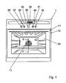
- the Control unit 34 has five housed in a housing arranged under a panel Operating elements, namely two operating buttons arranged below a time display 35 36, 37 for actuating a timer, one in the middle, one below Operating mode display 38 arranged, retractable knob 39 for selecting an operating mode and a retractable one located below a temperature display 40 Knob 41 for selecting an operating temperature and one next to the retractable knob 41 arranged actuation button 42 for activating a rapid heating unit or to set a quick heating mode.
- Operating elements namely two operating buttons arranged below a time display 35 36, 37 for actuating a timer, one in the middle, one below Operating mode display 38 arranged, retractable knob 39 for selecting an operating mode and a retractable one located below a temperature display 40
- Knob 41 for selecting an operating temperature and one next to the retractable knob 41 arranged actuation button 42 for activating a rapid heating unit or to set a quick heating mode.
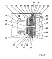
- the oven 1 also has a blower unit 13, one in the rear area of the Oven 1, arranged in a motor compartment 15, motor 16, via which with a through a partition 17 drive shaft 18 arranged in the cooking chamber 12 Fan 19 and an engine cooling fan 22 arranged in the engine compartment 15 can be driven (FIG. 2).
- the partition 17 extending perpendicular to the drive shaft 18 is separated by a Rear wall 53 of the muffle 33, an insulating layer 54 and through a wall 55 of the engine compartment 15 enclosing sheet metal container on which the motor 16 via fasteners 57 is attached, formed.
- the fan 19 has a disc-shaped component 44 with molded, axially Air blades 43 extending in the direction of the cooking space 12 for generating a hot air flow 47 in the cooking chamber 12, the fan 19 emitting air in the radially inner region sucks in the cooking space 12 and this in the radially outer area back into the cooking space 12 blows.
- the motor cooling fan 22 has a disk-shaped component 45 with molded, air blades 46 extending in the axial direction into the engine compartment 15 for generation a cooling air flow 48 in the engine compartment 15, the engine cooling fan 22 in the radial outer area sucks air from the engine compartment 15 and in the radially inner area blows back into the engine compartment 15 on the engine 16.
- the blower unit 13 also has an additional conveyor unit 20 for generating a Engine compartment 15 against vapor sealing gas pressure.
- the additional conveyor unit 20 has Air blades formed on the engine cooling fan 22 and extending in the direction of the cooking space 12 23 and formed on the fan 19, extending in the direction of the engine compartment 15 air vanes 24.
- the air blades 23, 24 are each evenly distributed over the circumference.
- the air blades 23 formed on the engine cooling fan 22 suck air radially from the outside on, they blow in the radially inner area in the direction of the cooking space 12 and in the radial direction inner region of the air blades 23 on the side of the partition 17 facing the Engine cooling fan 22 a pressure build-up and a small air flow 49 through one Annular gap 50 between the drive shaft 18 and the partition wall 17.
- Air blades 24 suck air radially from the inside, blow it radially outwards and cause in the radially outer region of the air blades 24 on the partition 17 facing side of the fan 19 build up pressure and a small air flow 51st
- the disk-shaped components 44, 45 of the fan 19 and the engine cooling fan 22 have a distance of approximately five millimeters from the partition 17 and the air blades 23, 24 the fan 19 and the engine cooling fan 22 a small sand of about two millimeters to the partition 17 and thereby form labyrinth sealing elements.
- the air blades 23, 24 are each in the radially inner region of the engine cooling fan 22 and the fan 19 formed.
- the air blades 23, 24 can thereby opposite Air blades arranged radially outer area with a small distance to Partition 17 can be arranged without these wobbling movements caused by tolerances or come into contact with the partition 17 by thermal deformation.
- FIGS. 1 and 2 show an alternative exemplary embodiment with a blower unit 14.
- Components that remain essentially the same are fundamentally identified by the same reference numerals quantified.
- the Description of the exemplary embodiment can be made in FIGS. 1 and 2. The the following description is essentially limited to the differences from Embodiment in Figs. 1 and 2.
- the blower unit 14 has an additional engine compartment 15 in an engine compartment 15 sealing labyrinth seal unit 26.
- the labyrinth seal unit 26 has a first, on a drive shaft 18 arranged in a rotationally fixed, disc-shaped sealing element 27, which is enclosed by a sheet metal sleeve 30, which on the engine compartment 15th facing side a radially inward, the first sealing element 27 in the radial direction overlapping second sealing element 28 forming collar.
- the sheet metal sleeve 30 is on the side facing a cooking chamber 12 with a radially outwardly extending collar 56 attached to a partition 17.
- the third sealing element 29 is made of an elastic, temperature-resistant plastic formed and grinds with its during operation Inner circumference on the drive shaft 18.
- the third sealing element 29 is as a grinding Executed seal, but could also be made contactless to the drive shaft 18 be, whereby the additional labyrinth seal unit 26 completely free of friction could be executed.
- the third sealing element could at least partially be made in one piece with the partition.
- the first sealing element 27 are in the direction of a motor 16 and in the direction of the cooking space 12 pointing air blades 31, 32 formed on an additional conveyor unit 21, each a small axial distance from the second or third sealing element 28, Have 29 of about two millimeters and form labyrinth sealing elements.
- the first Sealing element 27 is at a radial distance of approximately five millimeters from the sheet metal sleeve 30 to compensate for height tolerances of the drive shaft 18. Due to the radial Distance results in the radially outer area between the first sealing element 27 and the sheet metal sleeve 30 a kind of sealing chamber.
- the air blades 31 pointing in the direction of the motor 16 suck in the radially inner region Air and blow it radially outwards, whereas those pointing towards the cooking space Air blades 32 suck in air in the radially outer region and this in the radially inner region Blow the area towards the cooking chamber 12 so that in the sheet metal sleeve 30 one from the engine compartment 15 gas pressure acting in the direction of the cooking chamber 12 and sealing the engine compartment 15.
Landscapes
- Engineering & Computer Science (AREA)
- Chemical & Material Sciences (AREA)
- Combustion & Propulsion (AREA)
- Mechanical Engineering (AREA)
- General Engineering & Computer Science (AREA)
- Structures Of Non-Positive Displacement Pumps (AREA)
- Food-Manufacturing Devices (AREA)
- Sealing Using Fluids, Sealing Without Contact, And Removal Of Oil (AREA)
- Cookers (AREA)
- Ventilation (AREA)
Abstract
Description
- Fig. 1
- einen Backofen von vorn,
- Fig. 2
- einen schematisch dargestellten Ausschnitt eines Schnitts entlang der Linie II-II in Fig. 1 und
- Fig. 3
- eine Alternative zu Fig. 2 mit einer zusätzlichen Labyrinthdichtungseinheit.
Claims (12)
- Gargerät mit einem in einem Gehäuse (10) angeordneten, durch eine Tür (11) verschließbaren Garraum (12) und einer Gebläseeinheit (13, 14), die zumindest einen in einem Motorraum (15) angeordneten Motor (16) aufweist, über den mit einer durch eine Trennwand (17) geführten Antriebswelle (18) zumindest ein Lüfter (19) antreibbar ist, dadurch gekennzeichnet, daß die Gebläseeinheit (13, 14) eine Zusatzfördereinheit (20, 21) zur Erzeugung eines den Motorraum (15) gegen Wrasen abdichtenden Gasdrucks aufweist.
- Gargerät nach Anspruch 1, dadurch gekennzeichnet, daß die Zusatzfördereinheit (20) zumindest ein an einem im Motorraum (15) angeordneten Motor-Kühllüfter (22) angeordnetes Förderelement (23) aufweist.
- Gargerät nach einem der vorhergehenden Ansprüche, dadurch gekennzeichnet, daß die Zusatzfördereinheit (20) zumindest ein am Lüfter (19) angeordnetes Förderelement (24, 25) aufweist.
- Gargerät nach Anspruch 3, dadurch gekennzeichnet, daß das am Lüfter (19) angeordnete Förderelement (25) von einem axialen Förderkanal gebildet ist.
- Gargerät nach einem der Ansprüche 2 bis 4, dadurch gekennzeichnet, daß das Förderelement (23, 24) von einer Luftschaufel gebildet ist.
- Gargerät nach Anspruch 5, dadurch gekennzeichnet, daß das Förderelement (23, 24) ein Labyrinthdichtungselement bildet.
- Gargerät nach einem der vorhergehenden Ansprüche, dadurch gekennzeichnet, daß der Motorraum (15) über eine zusätzliche Labyrinthdichtungseinheit (26) abgedichtet ist.
- Gargerät nach Anspruch 7, dadurch gekennzeichnet, daß die Labyrinthdichtungseinheit (26) zumindest ein erstes Dichtungselement (27) aufweist, das zu einem dem Motor (16) zugewandten, hinteren zweiten Dichtungselement (28) und zu einem dem Motor (16) abgewandten, vorderen dritten Dichtungselement (29) überlappend angeordnet ist.
- Gargerät nach Anspruch 8, dadurch gekennzeichnet, daß das erste Dichtungselement (27) von einem auf der Antriebswelle (18) angeordneten, scheibenförmigen Bauteil gebildet ist, das von einer Hülse (30) umschlossen ist, die zumindest einen radial nach innen weisenden, eines der Dichtungselemente (28) bildenden Bund aufweist.
- Gargerät nach Anspruch 8 oder 9, dadurch gekennzeichnet, daß am ersten Dichtungselement (27) zumindest ein Förderelement (31, 32) der Zusatzfördereinheit (21) angeordnet ist.
- Gargerät nach Anspruch 10, dadurch gekennzeichnet, daß das Förderelement (31, 32) von einer in Richtung Garraum (12) und/oder einer in Richtung Motor (16) weisenden Luftschaufel gebildet ist.
- Gargerät nach Anspruch 10 oder 11, dadurch gekennzeichnet, daß das Förderelement (31, 32) ein Labyrinthdichtungselement bildet.
Applications Claiming Priority (2)
| Application Number | Priority Date | Filing Date | Title |
|---|---|---|---|
| DE10152733 | 2001-10-25 | ||
| DE10152733A DE10152733A1 (de) | 2001-10-25 | 2001-10-25 | Gargerät mit einer Gebläseeinheit |
Publications (4)
| Publication Number | Publication Date |
|---|---|
| EP1306623A2 true EP1306623A2 (de) | 2003-05-02 |
| EP1306623A3 EP1306623A3 (de) | 2005-04-13 |
| EP1306623B1 EP1306623B1 (de) | 2008-09-03 |
| EP1306623B2 EP1306623B2 (de) | 2013-03-13 |
Family
ID=7703716
Family Applications (1)
| Application Number | Title | Priority Date | Filing Date |
|---|---|---|---|
| EP02023237A Expired - Lifetime EP1306623B2 (de) | 2001-10-25 | 2002-10-16 | Gargerät mit einer Gebläseeinheit |
Country Status (4)
| Country | Link |
|---|---|
| EP (1) | EP1306623B2 (de) |
| AT (1) | ATE407332T1 (de) |
| DE (2) | DE10152733A1 (de) |
| ES (1) | ES2312517T5 (de) |
Cited By (3)
| Publication number | Priority date | Publication date | Assignee | Title |
|---|---|---|---|---|
| EP1467154A3 (de) * | 2003-04-10 | 2005-05-25 | Samsung Electronics Co., Ltd. | Gargerät |
| US7766003B2 (en) * | 2007-10-09 | 2010-08-03 | Samsung Electronics Co., Ltd. | Cooking apparatus and method for controlling the same |
| WO2018007318A1 (de) * | 2016-07-04 | 2018-01-11 | Convotherm-Elektrogeräte Gmbh | Gewerbliches gargerät |
Families Citing this family (4)
| Publication number | Priority date | Publication date | Assignee | Title |
|---|---|---|---|---|
| DE102004031159B4 (de) * | 2004-06-28 | 2017-02-02 | BSH Hausgeräte GmbH | Gebläsevorrichtung |
| DE102011075628A1 (de) | 2011-05-11 | 2012-11-15 | BSH Bosch und Siemens Hausgeräte GmbH | Radiallüfterrad und Haushaltsgerät mit einem Radiallüfterrad |
| DE102014110463A1 (de) * | 2014-07-24 | 2016-01-28 | Rational Aktiengesellschaft | Gargerät |
| EP4317701A4 (de) * | 2021-03-30 | 2024-09-25 | Panasonic Intellectual Property Management Co., Ltd. | Elektrisches luftgebläse und kühlgebläse |
Family Cites Families (8)
| Publication number | Priority date | Publication date | Assignee | Title |
|---|---|---|---|---|
| DE7315732U (de) * | 1973-04-26 | 1973-10-11 | Licentia Gmbh | Bratofen mit beheizung und einem geblaese |
| DE2460294C3 (de) * | 1974-12-19 | 1981-07-30 | Bosch-Siemens Hausgeräte GmbH, 7000 Stuttgart | Garbehälter zum Backen, Braten und Grillen mit einem Heißluft-Umwälzgebläse, insbesondere Back- und Bratrohr mit pyrolytischer Selbstreinigung |
| JPS596322Y2 (ja) * | 1979-04-24 | 1984-02-27 | リンナイ株式会社 | 高周波調理器 |
| DE3016260A1 (de) * | 1980-04-26 | 1981-10-29 | Gaggenau-Werke Haus- Und Lufttechnik Gmbh, 7560 Gaggenau | Verfahren und vorrichtung zur steuerung der temperatur und der foerderleistung des geblaeses in einem heissluftofen |
| DE3324076A1 (de) * | 1983-03-17 | 1984-09-27 | Bosch-Siemens Hausgeräte GmbH, 7000 Stuttgart | Geblaese fuer die luftumwaelzung in backoefen |
| DE3345746C3 (de) * | 1983-12-17 | 1995-04-06 | Licentia Gmbh | Back- u. Bratofen mit einem Umluftgebläse |
| GB2286455B (en) * | 1994-02-10 | 1998-01-14 | Stoves Plc | Improvements in and relating to gaseous fuel burner assemblies and to appliances incorporating such burner assemblies |
| DE29823447U1 (de) * | 1998-03-09 | 1999-08-05 | BSH Bosch und Siemens Hausgeräte GmbH, 81669 München | Backofen mit Sauggehäuse |
-
2001
- 2001-10-25 DE DE10152733A patent/DE10152733A1/de not_active Withdrawn
-
2002
- 2002-10-16 ES ES02023237T patent/ES2312517T5/es not_active Expired - Lifetime
- 2002-10-16 EP EP02023237A patent/EP1306623B2/de not_active Expired - Lifetime
- 2002-10-16 AT AT02023237T patent/ATE407332T1/de not_active IP Right Cessation
- 2002-10-16 DE DE50212723T patent/DE50212723D1/de not_active Expired - Lifetime
Cited By (4)
| Publication number | Priority date | Publication date | Assignee | Title |
|---|---|---|---|---|
| EP1467154A3 (de) * | 2003-04-10 | 2005-05-25 | Samsung Electronics Co., Ltd. | Gargerät |
| US7766003B2 (en) * | 2007-10-09 | 2010-08-03 | Samsung Electronics Co., Ltd. | Cooking apparatus and method for controlling the same |
| WO2018007318A1 (de) * | 2016-07-04 | 2018-01-11 | Convotherm-Elektrogeräte Gmbh | Gewerbliches gargerät |
| EP3686497A1 (de) * | 2016-07-04 | 2020-07-29 | Convotherm Elektrogeräte GmbH | Gewerbliches gargerät |
Also Published As
| Publication number | Publication date |
|---|---|
| ES2312517T3 (es) | 2009-03-01 |
| EP1306623B2 (de) | 2013-03-13 |
| ES2312517T5 (es) | 2013-05-31 |
| ATE407332T1 (de) | 2008-09-15 |
| DE50212723D1 (de) | 2008-10-16 |
| EP1306623A3 (de) | 2005-04-13 |
| EP1306623B1 (de) | 2008-09-03 |
| DE10152733A1 (de) | 2003-05-08 |
Similar Documents
| Publication | Publication Date | Title |
|---|---|---|
| DE3839657C2 (de) | Luftführungssystem für einen Backofen | |
| DE102017217853B4 (de) | Kochfeldsystem mit Dunstabzugsvorrichtung | |
| DE3427565C2 (de) | Durch einen Elektromotor angetriebenes Radialgebläse | |
| WO2017029128A1 (de) | Kombinationsgerät mit kochfeld und dunstabzugsvorrichtung | |
| DE3516847A1 (de) | Elektroherd mit katalysator | |
| EP1004826B1 (de) | Garofen mit Kühlung und Wrasenabführung | |
| DE3636622C2 (de) | Back- oder Bratofen mit einem Heizgebläse und einem Katalysator | |
| DE102019210974A1 (de) | Kochfeldsystem und Dunstabzugsvorrichtung zum Abzug von Kochdünsten nach unten | |
| EP1306623B1 (de) | Gargerät mit einer Gebläseeinheit | |
| DE19920345C1 (de) | Garofen mit Wrasenabführung und Frischluftbeimischung | |
| DE2139488A1 (de) | Regenerierender Raumerhitzer | |
| DE2649528C2 (de) | Elektroherd mit Luftumwälzung im Ofenraum | |
| DE102012204234A1 (de) | Mikrowellen-Kombigerät mit einem Gebläse zur Kühlung | |
| EP0633433B1 (de) | Einbauherd | |
| DE3346019C2 (de) | Backofen | |
| EP0942235A1 (de) | Backofen mit Sauggehäuse | |
| DE2106869B2 (de) | Haushaltsbackofen | |
| DE2615604A1 (de) | Backofen, insbesondere mit mitteln zur pyrolytischen reinigung | |
| EP3872405A2 (de) | Vorrichtung zum erhitzen von gargut | |
| EP1014002B1 (de) | Herd, insbesondere Elektroherd | |
| DE4142474A1 (de) | Dunstabzugshaube | |
| EP0172900B1 (de) | Vorrichtung zum transport und/oder zur vermischung von gasen | |
| DE10314572A1 (de) | Gargerät | |
| EP1342034A1 (de) | Gargerät | |
| DE3118463C2 (de) |
Legal Events
| Date | Code | Title | Description |
|---|---|---|---|
| PUAI | Public reference made under article 153(3) epc to a published international application that has entered the european phase |
Free format text: ORIGINAL CODE: 0009012 |
|
| AK | Designated contracting states |
Designated state(s): AT BE BG CH CY CZ DE DK EE ES FI FR GB GR IE IT LI LU MC NL PT SE SK TR |
|
| AX | Request for extension of the european patent |
Extension state: AL LT LV MK RO SI |
|
| RAP1 | Party data changed (applicant data changed or rights of an application transferred) |
Owner name: BSH BOSCH UND SIEMENS HAUSGERAETE GMBH |
|
| PUAL | Search report despatched |
Free format text: ORIGINAL CODE: 0009013 |
|
| AK | Designated contracting states |
Kind code of ref document: A3 Designated state(s): AT BE BG CH CY CZ DE DK EE ES FI FR GB GR IE IT LI LU MC NL PT SE SK TR |
|
| AX | Request for extension of the european patent |
Extension state: AL LT LV MK RO SI |
|
| 17P | Request for examination filed |
Effective date: 20051013 |
|
| AKX | Designation fees paid |
Designated state(s): AT BE BG CH CY CZ DE DK EE ES FI FR GB GR IE IT LI LU MC NL PT SE SK TR |
|
| AXX | Extension fees paid |
Extension state: SI Payment date: 20051013 |
|
| 17Q | First examination report despatched |
Effective date: 20070525 |
|
| GRAP | Despatch of communication of intention to grant a patent |
Free format text: ORIGINAL CODE: EPIDOSNIGR1 |
|
| GRAS | Grant fee paid |
Free format text: ORIGINAL CODE: EPIDOSNIGR3 |
|
| GRAA | (expected) grant |
Free format text: ORIGINAL CODE: 0009210 |
|
| AK | Designated contracting states |
Kind code of ref document: B1 Designated state(s): AT BE BG CH CY CZ DE DK EE ES FI FR GB GR IE IT LI LU MC NL PT SE SK TR |
|
| AX | Request for extension of the european patent |
Extension state: SI |
|
| REG | Reference to a national code |
Ref country code: GB Ref legal event code: FG4D Free format text: NOT ENGLISH |
|
| REG | Reference to a national code |
Ref country code: CH Ref legal event code: EP |
|
| REG | Reference to a national code |
Ref country code: IE Ref legal event code: FG4D Free format text: LANGUAGE OF EP DOCUMENT: GERMAN |
|
| REF | Corresponds to: |
Ref document number: 50212723 Country of ref document: DE Date of ref document: 20081016 Kind code of ref document: P |
|
| PG25 | Lapsed in a contracting state [announced via postgrant information from national office to epo] |
Ref country code: NL Free format text: LAPSE BECAUSE OF FAILURE TO SUBMIT A TRANSLATION OF THE DESCRIPTION OR TO PAY THE FEE WITHIN THE PRESCRIBED TIME-LIMIT Effective date: 20080903 |
|
| PG25 | Lapsed in a contracting state [announced via postgrant information from national office to epo] |
Ref country code: FI Free format text: LAPSE BECAUSE OF FAILURE TO SUBMIT A TRANSLATION OF THE DESCRIPTION OR TO PAY THE FEE WITHIN THE PRESCRIBED TIME-LIMIT Effective date: 20080903 |
|
| REG | Reference to a national code |
Ref country code: ES Ref legal event code: FG2A Ref document number: 2312517 Country of ref document: ES Kind code of ref document: T3 |
|
| NLV1 | Nl: lapsed or annulled due to failure to fulfill the requirements of art. 29p and 29m of the patents act | ||
| REG | Reference to a national code |
Ref country code: IE Ref legal event code: FD4D |
|
| BERE | Be: lapsed |
Owner name: BSH BOSCH UND SIEMENS HAUSGERATE G.M.B.H. Effective date: 20081031 |
|
| PG25 | Lapsed in a contracting state [announced via postgrant information from national office to epo] |
Ref country code: IE Free format text: LAPSE BECAUSE OF FAILURE TO SUBMIT A TRANSLATION OF THE DESCRIPTION OR TO PAY THE FEE WITHIN THE PRESCRIBED TIME-LIMIT Effective date: 20080903 Ref country code: BG Free format text: LAPSE BECAUSE OF FAILURE TO SUBMIT A TRANSLATION OF THE DESCRIPTION OR TO PAY THE FEE WITHIN THE PRESCRIBED TIME-LIMIT Effective date: 20081203 |
|
| PG25 | Lapsed in a contracting state [announced via postgrant information from national office to epo] |
Ref country code: MC Free format text: LAPSE BECAUSE OF NON-PAYMENT OF DUE FEES Effective date: 20081031 Ref country code: CZ Free format text: LAPSE BECAUSE OF FAILURE TO SUBMIT A TRANSLATION OF THE DESCRIPTION OR TO PAY THE FEE WITHIN THE PRESCRIBED TIME-LIMIT Effective date: 20080903 Ref country code: PT Free format text: LAPSE BECAUSE OF FAILURE TO SUBMIT A TRANSLATION OF THE DESCRIPTION OR TO PAY THE FEE WITHIN THE PRESCRIBED TIME-LIMIT Effective date: 20090203 Ref country code: SK Free format text: LAPSE BECAUSE OF FAILURE TO SUBMIT A TRANSLATION OF THE DESCRIPTION OR TO PAY THE FEE WITHIN THE PRESCRIBED TIME-LIMIT Effective date: 20080903 |
|
| REG | Reference to a national code |
Ref country code: CH Ref legal event code: PL |
|
| PLBI | Opposition filed |
Free format text: ORIGINAL CODE: 0009260 |
|
| PLAX | Notice of opposition and request to file observation + time limit sent |
Free format text: ORIGINAL CODE: EPIDOSNOBS2 |
|
| 26 | Opposition filed |
Opponent name: AEG HAUSGERAETE GMBH Effective date: 20090602 |
|
| PG25 | Lapsed in a contracting state [announced via postgrant information from national office to epo] |
Ref country code: EE Free format text: LAPSE BECAUSE OF FAILURE TO SUBMIT A TRANSLATION OF THE DESCRIPTION OR TO PAY THE FEE WITHIN THE PRESCRIBED TIME-LIMIT Effective date: 20080903 Ref country code: DK Free format text: LAPSE BECAUSE OF FAILURE TO SUBMIT A TRANSLATION OF THE DESCRIPTION OR TO PAY THE FEE WITHIN THE PRESCRIBED TIME-LIMIT Effective date: 20080903 |
|
| PG25 | Lapsed in a contracting state [announced via postgrant information from national office to epo] |
Ref country code: BE Free format text: LAPSE BECAUSE OF NON-PAYMENT OF DUE FEES Effective date: 20081031 |
|
| PG25 | Lapsed in a contracting state [announced via postgrant information from national office to epo] |
Ref country code: CH Free format text: LAPSE BECAUSE OF NON-PAYMENT OF DUE FEES Effective date: 20081031 Ref country code: LI Free format text: LAPSE BECAUSE OF NON-PAYMENT OF DUE FEES Effective date: 20081031 |
|
| PLAF | Information modified related to communication of a notice of opposition and request to file observations + time limit |
Free format text: ORIGINAL CODE: EPIDOSCOBS2 |
|
| PLBB | Reply of patent proprietor to notice(s) of opposition received |
Free format text: ORIGINAL CODE: EPIDOSNOBS3 |
|
| PG25 | Lapsed in a contracting state [announced via postgrant information from national office to epo] |
Ref country code: AT Free format text: LAPSE BECAUSE OF NON-PAYMENT OF DUE FEES Effective date: 20081016 Ref country code: SE Free format text: LAPSE BECAUSE OF FAILURE TO SUBMIT A TRANSLATION OF THE DESCRIPTION OR TO PAY THE FEE WITHIN THE PRESCRIBED TIME-LIMIT Effective date: 20081203 |
|
| PG25 | Lapsed in a contracting state [announced via postgrant information from national office to epo] |
Ref country code: LU Free format text: LAPSE BECAUSE OF NON-PAYMENT OF DUE FEES Effective date: 20081016 Ref country code: CY Free format text: LAPSE BECAUSE OF FAILURE TO SUBMIT A TRANSLATION OF THE DESCRIPTION OR TO PAY THE FEE WITHIN THE PRESCRIBED TIME-LIMIT Effective date: 20080903 |
|
| PG25 | Lapsed in a contracting state [announced via postgrant information from national office to epo] |
Ref country code: GR Free format text: LAPSE BECAUSE OF FAILURE TO SUBMIT A TRANSLATION OF THE DESCRIPTION OR TO PAY THE FEE WITHIN THE PRESCRIBED TIME-LIMIT Effective date: 20081204 |
|
| PLAB | Opposition data, opponent's data or that of the opponent's representative modified |
Free format text: ORIGINAL CODE: 0009299OPPO |
|
| R26 | Opposition filed (corrected) |
Opponent name: ELECTROLUX ROTHENBURG GMBH FACTORY AND DEVELOPMENT Effective date: 20090602 |
|
| PUAH | Patent maintained in amended form |
Free format text: ORIGINAL CODE: 0009272 |
|
| STAA | Information on the status of an ep patent application or granted ep patent |
Free format text: STATUS: PATENT MAINTAINED AS AMENDED |
|
| 27A | Patent maintained in amended form |
Effective date: 20130313 |
|
| AK | Designated contracting states |
Kind code of ref document: B2 Designated state(s): AT BE BG CH CY CZ DE DK EE ES FI FR GB GR IE IT LI LU MC NL PT SE SK TR |
|
| AX | Request for extension of the european patent |
Extension state: SI |
|
| REG | Reference to a national code |
Ref country code: DE Ref legal event code: R102 Ref document number: 50212723 Country of ref document: DE Effective date: 20130313 |
|
| REG | Reference to a national code |
Ref country code: ES Ref legal event code: DC2A Ref document number: 2312517 Country of ref document: ES Kind code of ref document: T5 Effective date: 20130531 |
|
| REG | Reference to a national code |
Ref country code: DE Ref legal event code: R081 Ref document number: 50212723 Country of ref document: DE Owner name: BSH HAUSGERAETE GMBH, DE Free format text: FORMER OWNER: BSH BOSCH UND SIEMENS HAUSGERAETE GMBH, 81739 MUENCHEN, DE Effective date: 20150407 |
|
| REG | Reference to a national code |
Ref country code: ES Ref legal event code: PC2A Owner name: BSH HAUSGERATE GMBH Effective date: 20150527 |
|
| REG | Reference to a national code |
Ref country code: FR Ref legal event code: PLFP Year of fee payment: 14 |
|
| REG | Reference to a national code |
Ref country code: FR Ref legal event code: CD Owner name: BSH HAUSGERATE GMBH Effective date: 20151022 |
|
| PGFP | Annual fee paid to national office [announced via postgrant information from national office to epo] |
Ref country code: DE Payment date: 20151031 Year of fee payment: 14 Ref country code: IT Payment date: 20151026 Year of fee payment: 14 Ref country code: GB Payment date: 20151026 Year of fee payment: 14 |
|
| PGFP | Annual fee paid to national office [announced via postgrant information from national office to epo] |
Ref country code: ES Payment date: 20151023 Year of fee payment: 14 Ref country code: FR Payment date: 20151026 Year of fee payment: 14 |
|
| PGFP | Annual fee paid to national office [announced via postgrant information from national office to epo] |
Ref country code: TR Payment date: 20161005 Year of fee payment: 15 |
|
| REG | Reference to a national code |
Ref country code: DE Ref legal event code: R119 Ref document number: 50212723 Country of ref document: DE |
|
| GBPC | Gb: european patent ceased through non-payment of renewal fee |
Effective date: 20161016 |
|
| REG | Reference to a national code |
Ref country code: FR Ref legal event code: ST Effective date: 20170630 |
|
| PG25 | Lapsed in a contracting state [announced via postgrant information from national office to epo] |
Ref country code: FR Free format text: LAPSE BECAUSE OF NON-PAYMENT OF DUE FEES Effective date: 20161102 Ref country code: GB Free format text: LAPSE BECAUSE OF NON-PAYMENT OF DUE FEES Effective date: 20161016 Ref country code: DE Free format text: LAPSE BECAUSE OF NON-PAYMENT OF DUE FEES Effective date: 20170503 |
|
| PG25 | Lapsed in a contracting state [announced via postgrant information from national office to epo] |
Ref country code: IT Free format text: LAPSE BECAUSE OF NON-PAYMENT OF DUE FEES Effective date: 20161016 |
|
| REG | Reference to a national code |
Ref country code: ES Ref legal event code: FD2A Effective date: 20180507 |
|
| PG25 | Lapsed in a contracting state [announced via postgrant information from national office to epo] |
Ref country code: ES Free format text: LAPSE BECAUSE OF FAILURE TO SUBMIT A TRANSLATION OF THE DESCRIPTION OR TO PAY THE FEE WITHIN THE PRESCRIBED TIME-LIMIT Effective date: 20080903 |
|
| PG25 | Lapsed in a contracting state [announced via postgrant information from national office to epo] |
Ref country code: ES Free format text: LAPSE BECAUSE OF FAILURE TO SUBMIT A TRANSLATION OF THE DESCRIPTION OR TO PAY THE FEE WITHIN THE PRESCRIBED TIME-LIMIT Effective date: 20161017 |
|
| PG25 | Lapsed in a contracting state [announced via postgrant information from national office to epo] |
Ref country code: TR Free format text: LAPSE BECAUSE OF NON-PAYMENT OF DUE FEES Effective date: 20171016 |