EP1306033B1 - Stuhl - Google Patents
Stuhl Download PDFInfo
- Publication number
- EP1306033B1 EP1306033B1 EP02023419A EP02023419A EP1306033B1 EP 1306033 B1 EP1306033 B1 EP 1306033B1 EP 02023419 A EP02023419 A EP 02023419A EP 02023419 A EP02023419 A EP 02023419A EP 1306033 B1 EP1306033 B1 EP 1306033B1
- Authority
- EP
- European Patent Office
- Prior art keywords
- chair
- seat frame
- seat
- fact
- elements
- Prior art date
- Legal status (The legal status is an assumption and is not a legal conclusion. Google has not performed a legal analysis and makes no representation as to the accuracy of the status listed.)
- Expired - Lifetime
Links
Images


Classifications
-
- A—HUMAN NECESSITIES
- A47—FURNITURE; DOMESTIC ARTICLES OR APPLIANCES; COFFEE MILLS; SPICE MILLS; SUCTION CLEANERS IN GENERAL
- A47C—CHAIRS; SOFAS; BEDS
- A47C7/00—Parts, details, or accessories of chairs or stools
- A47C7/36—Support for the head or the back
- A47C7/38—Support for the head or the back for the head
-
- A—HUMAN NECESSITIES
- A47—FURNITURE; DOMESTIC ARTICLES OR APPLIANCES; COFFEE MILLS; SPICE MILLS; SUCTION CLEANERS IN GENERAL
- A47C—CHAIRS; SOFAS; BEDS
- A47C1/00—Chairs adapted for special purposes
- A47C1/02—Reclining or easy chairs
- A47C1/022—Reclining or easy chairs having independently-adjustable supporting parts
- A47C1/024—Reclining or easy chairs having independently-adjustable supporting parts the parts, being the back-rest, or the back-rest and seat unit, having adjustable and lockable inclination
-
- A—HUMAN NECESSITIES
- A47—FURNITURE; DOMESTIC ARTICLES OR APPLIANCES; COFFEE MILLS; SPICE MILLS; SUCTION CLEANERS IN GENERAL
- A47C—CHAIRS; SOFAS; BEDS
- A47C7/00—Parts, details, or accessories of chairs or stools
- A47C7/36—Support for the head or the back
- A47C7/40—Support for the head or the back for the back
- A47C7/405—Support for the head or the back for the back with double backrests
-
- A—HUMAN NECESSITIES
- A47—FURNITURE; DOMESTIC ARTICLES OR APPLIANCES; COFFEE MILLS; SPICE MILLS; SUCTION CLEANERS IN GENERAL
- A47C—CHAIRS; SOFAS; BEDS
- A47C7/00—Parts, details, or accessories of chairs or stools
- A47C7/36—Support for the head or the back
- A47C7/40—Support for the head or the back for the back
- A47C7/44—Support for the head or the back for the back with elastically-mounted back-rest or backrest-seat unit in the base frame
- A47C7/448—Support for the head or the back for the back with elastically-mounted back-rest or backrest-seat unit in the base frame with resilient blocks
-
- A—HUMAN NECESSITIES
- A47—FURNITURE; DOMESTIC ARTICLES OR APPLIANCES; COFFEE MILLS; SPICE MILLS; SUCTION CLEANERS IN GENERAL
- A47C—CHAIRS; SOFAS; BEDS
- A47C7/00—Parts, details, or accessories of chairs or stools
- A47C7/36—Support for the head or the back
- A47C7/40—Support for the head or the back for the back
- A47C7/46—Support for the head or the back for the back with special, e.g. adjustable, lumbar region support profile; "Ackerblom" profile chairs
Definitions
- a chair in particular a Office or work chair, with movable seat and mobile backrest, and arranged in the rear region of the seat cushion / arranged Stützelementbefest Trent / s (17) in or on each of which a flexurally elastic Supporting element (18) is attached, wherein along each support element (18) Compression spring elements (20) and extending over the spine width Shaping elements (21) each adjacent to each other alternately one above the other are arranged, which is characterized in that the lower Mold element (21) / or more of the lower mold elements (21) with each other by means of one or more arranged symmetrically to the center flexurally elastic / flexurally elastic stiffening element / stiffening elements (26) connected to one or more pivot lever (s) (27) is / are, which in one or more associated with the seat frame (5) and / or bearings (15) arranged on an adapter element (35) is pivotally mounted / are, wherein on the respective pivot lever (27) a Wegbeg
- the adapter element (35) is fastened to the seat frame (5) and / or to the padding plate (8).
- the backrests according to the invention without seat mechanism but also with any seat mechanism can be combined with both, as well as without armrests.
- the adapter element (35) consists of two carrier bars (36), a connecting web (37) arranged between these carrier bars (36) and a molded part (38) arranged above the carrier bars (36) and the connecting bar (37). The rigid connection of these modules together ensures an aesthetically sophisticated, cost-effective and functionally reliable attachment of the functional assemblies on the adapter element (35).
- the carrier bars (36) and the connecting web (37) from below, and the molded part (38) are rigidly connected to the pad plate (8) from behind.
- a functionally reliable, aesthetically sophisticated attachment of the adapter element to the pad plate (8) is ensured.
- the guide groove and / or the slotted guide are incorporated from the inside in each case in the side cheek of the seat frame. As a result, a risk of injury to the gear units of the chair is excluded.
- a slot is arranged in which a slidably mounted in the slot, lockable clamping element is arranged, which arranged with a in the region of the intermediate plate on the clamping element Actuator in the clamped state acts on the intermediate plate and thus restricts the mutual relative movement between the intermediate plate and the seat frame. This makes it possible to limit the "swing mechanism" of the seat in this as the end position in any seat position.
- a knob 24 for adjusting the Verstellhärte the Wegverstellmechanik and a mounted in a slot 31 of the side cheek 19 of the seat frame 5 clamping element 32 are further arranged for Endlagenbegrenzung the Wegverstellmechanik.
- Behind the seat cushion two bending elastic, consisting for example of glass fiber rods support elements 18 are arranged symmetrically to the chair center axis on the seat frame 5.
- At the flexurally elastic support elements 18 are adjacent to each other, for example made of elastic plastic (eg polyurethane foam) existing compression spring elements 20 and over the spine width extending form elements 21 arranged alternately one above the other.
- the over the spine width extending mold elements 21 are preferably constructed in regions partially different geometrically.
- These guide rollers 4 are slidably arranged at the front in the horizontal guide grooves 6 and rear in the arcuate slotted guides 7 of the side cheeks 19 of the seat frame 5.
- the guide grooves 6 and the arcuate slotted guides 7 are incorporated from the inside in each case in the side cheek 19 of the seat frame 5, wherein in a side cheek 19 with a thickness of for example 24 mm, the guide grooves 6 and the slotted guides 7, for example, about 15 mm deep are incorporated.
- the cushion plate 8 is arranged with the seat cushion.
- a biasing element 9 is also attached, which can be actuated by means of the knob 24.
- a spring element 11 is arranged between the biasing element 9 and a fastening element 10 arranged on the intermediate plate 3.
- two support element fastenings 17 in the form of fastening bores 23 with or without insertion sleeves are arranged on the seat frame 5 (as far as the side cheeks 19) symmetrically with respect to the chair center axis.
- the bending elastic consisting for example of glass fiber rods support elements 18 are arranged.
- compression spring elements 20 arranged adjacent to each other from PUR foam sleeves and form elements 21 extending over the spine width, in some areas similar or also differently dimensioned, are arranged alternately one above the other on the flexurally elastic support elements 18.
- the lower mold elements 21 are connected to each other by means of a symmetrical to the middle between the support members 18 arranged flexible elastic stiffening element 26 (see also Figure 1), which is arranged on a between the support elements 18 on the seat frame 5 on two bearings 15 by means of an axis 16 pivotally mounted pivoting lever 27 is.
- On the pivot lever 27 is a Wegbegrenzungs- / biasing member 28 and the seat frame 5 with the Wegbegrenzungs- / biasing member 28 in operative connection passing stop 29 is arranged.
- the stroke of Wegbegrenzungs- / biasing member 28 may, as shown in Figure 2, are adjusted relative to the stop on the seat frame 5 by means of an adjusting element 30.
- the arrangement of the support member 18 causes the reclining anatomical, elastic support of the upper body can be realized in the lumbar region, by means of the adjustment 30 also the "hardness" of the lumbar support can be adapted to the user's needs, so that due to the inventive arrangement when leaning back a variable, anatomical, elastic support of the upper body is realized in the lumbar region.
- a lockable clamping element 32 is arranged in the side cheek 19 of the seat frame 5 .
- FIG. 3 shows the adjustment unit of the chair according to the invention in a further design in the perspective view obliquely from behind. On the pad plate 8, the adapter element 35 is attached.
- This adapter element 35 consists of two carrier bars 36, a connecting web 37 arranged between these carrier bars 36 and a shaped part 38 arranged above the carrier bars 36 and the connecting bar 37.
- the support bars 36 and the connecting web 37 are rigid with the pad plate 8 from below, and the molding 38 is rigidly connected to the pad plate 8 from behind.
- At least the lower mold element 21 is / (but also several of the lower mold elements 21 can be connected to each other) by means of a centrally arranged flexurally elastic stiffening element 26 with the pivot lever 27 (to be).
- In the adapter element 35 two projecting through the molding 38 in the support members 36 support element fasteners 17 are arranged. In these, the flexurally elastic support elements are attached.
- each compression spring element 20 attached to the two support elements 18.
- a pivot lever 27 is pivotally mounted on the molded part 38 of the adapter element 35 by means of a bearing 15 and an axis 16 arranged in this bearing 15.
- a Wegbegrenzungs- / biasing element 28 is arranged at the pivot lever 27, at the connecting web 37 there is a stop 29 which comes into operative connection with the travel limiting / pretensioning element 28.
- the stroke / the bias of Wegbegrenzungs- / biasing member 28 is adjustable relative to the stop 29 by means of an adjusting element 30.
- an adjusting element 30 By means of the variation of the stroke / the bias of Wegbegrenzungs- / biasing element 28 is on the body height and thus on the body weight individually adjustable, anatomy-friendly, also dependent on the respective work attitude, optimal, elastic adjustment of the support function allows, so that in any arbitrary Sitting position regardless of the seat position individually adjustable elastic supported variation of the body opening angle can be ensured with elastic support in the lumbar region with simultaneous elastically supported torsion of the back.
- the armrest support 12 and the seat mechanism 39 are further arranged.
Description
So versuchte man mit der in der DE OS 41 35 948 vorgestellten Lösung einen Stuhl zu entwickeln, welcher die Überführung in eine möglichst bequeme Ruhestellung erlaubt.
Um dabei den den bisherigen Bauformen anhaftenden "Hemdauszieheffekt", welcher durch die Abwärts- bzw. Aufwärtsbewegung des Rückens entlang der Rückenlehne hervorgerufen wird, zu vermeiden, wird auf eine aus einem schalenförmigen Bauteil bestehende Rückenlehne zurückgegriffen.
Der Rückenlehnenträger wird dabei unabhängig vom Sitzteilträger bewegt.
Die in Verbindung mit der Verschiebemechanik der Sitzfläche eingesetzte Synchronmechanik der im DE OS 41 35 948 vorgestellten Lösung bewirkt zwangsläufig, daß sich beim "Zurückfahren" der Sitzfläche diese zwar anatomiegerecht hinten anhebt, da jedoch gleichzeitig die Rückenlehne nach vorn klappt, kann der durch die Verwandlungsgeometrie vorgegebene Körperöffnungswinkel nicht unabhängig von der Sitzflächenstellung variiert werden, so daß mittels dieser Bauform zwangsläufig die inneren Organe "eingeklemmt" werden.
Da beim Zurücklehnen der Rücken gegenüber einer aufrechter Sitzhaltung in der Rückenschale zudem in einem höheren Abschnitt abgestützt wird, wird infolge der in dieser Lösung gewählten schwenkbaren Lagerung der Rückenlehne das untere Ende der Rückenlehne in den Lendenbereich der sitzenden Person gepresst, so daß mit dieser Bauform eine variable, anatomiegerechte, elastische Abstützung des Oberkörpers im Lendenbereich beim Zurücklehnen nicht realisiert werden kann, wobei ein anatomiegerechtes, torsionsartiges Verdrehen der Rückenlehne in jeder beliebigen Sitzstellung nicht möglich ist.
In der DE 100 50 430 A1 wird ein Stuhl mit beweglichem Sitz- und beweglicher Rückenlehne vorgestellt, bei dem im rückwärtigen Bereich des Sitzpolsters zwei Stützelementbefestigungen angeordnet sind in denen jeweils ein biegeelastisches Stützelement befestigt ist, wobei entlang jedes Stützelementes Druckfederelemente (20) und sich über die Rückenbreite erstreckende Formelemente (21) jeweils einander benachbart abwechselnd übereinander angeordnet sind. Mittels dieser Lösung ist zwar ein torsionsartiges Verdrehen und anatomiegerechtes Verbiegen der Rückenlehne möglich, so dass eine elastisch abgestützte Verdrehung des Rückens bei gleichzeitiger elastisch abgestützter Variation des Körperöffnungswinkels ermöglicht werden kann.
Der wesentliche Nachteil dieser Bauform besteht jedoch darin, daß die jeweiligen Abstützkräfte, bzw. Abstützmomente nicht benutzerdefiniert variiert werden können.
Die erfindungsgemäße spezielle Anordnung von nur einem Versteifungselement (26) bewirkt beispielsweise, daß beim Zurücklehnen eine anatomiegerechte, biegeelastisch einstellbare Abstützung des Oberkörpers mit elastischer Unterstützung im Lendenbereich bei gleichzeitiger elastisch abgestützter Verdrehung des Rückens realisiert werden kann.
Werden entlang der Rückenlehne beispielsweise symmetrisch zwei Versteifungselemente (26) eingesetzt, so kann mit der Abstützung des Oberkörpers beim Zurücklehnen auch die Abstützung des Oberkörpers beim Verdrehen gleichzeitig variiert werden.
Werden entlang der Rückenlehne hingegen drei Versteifungselemente (26) eingesetzt, beispielsweise eines mittig und die beiden anderen symmetrisch zu diesem, so kann die Abstützung des Oberkörpers beim Zurücklehnen unabhängig von der Abstützung des Oberkörpers beim Verdrehen variiert werden.
Dadurch können die erfindungsgemäßen Rückenlehnen ohne Sitzmechanik aber auch mit jeder beliebigen Sitzmechanik sowohl mit, wie auch ohne Armstützen kombiniert werden.
Kennzeichnend ist dabei, daß das Adapterelement (35) aus zwei Trägerholmen (36), einem zwischen diesen Trägerholmen (36) angeordneten Verbindungssteg (37) und einem oberhalb der Trägerholme (36) und dem Verbindungssteg (37) angeordnetem Formteil (38) besteht.
Die starre Verbindung dieser Baugruppen miteinander gewährleistet eine ästhetisch anspruchsvolle, kostengünstige und funktionssichere Befestigung der Funktionsbaugruppen am Adapterelement (35).
Erfindungswesentlich ist auch, daß die Trägerholme (36) und der Verbindungssteg (37) von unten, und das Formteil (38) von hinten biegesteif mit der Polsterplatte (8) verbunden sind. Dadurch wird eine funktionssichere, ästhetisch anspruchsvolle Befestigung des Adapterelementes an der Polsterplatte (8) gewährleistet.
Kennzeichnend ist auch, daß die Führungsnut und/ oder die Kulissenführung von innen jeweils in die Seitenwange des Sitzrahmens eingearbeitet sind.
Dadurch wird eine Verletzungsgefahr an den Getriebebaugruppen des Stuhles ausgeschlossen.
Ein weiteres Merkmal der Erfindung besteht darin, daß in der Seitenwange des Sitzrahmens ein Langloch angeordnet ist, in dem ein im Langloch verschiebbar gelagertes, arretierbares Spannelement angeordnet ist, welches mit einem im Bereich der Zwischenplatte am Spannelement angeordneten
Betätigungselement im verspannten Zustand auf die Zwischenplatte einwirkt und so die gegenseitige Relativbewegung zwischen der Zwischenplatte und dem Sitzrahmen einschränkt.
Dadurch ist es möglich in jeder beliebigen Sitzposition die "Schwenkmechanik" der Sitzfläche in dieser als Endlage zu begrenzen.
- Figur 1 :
- eine mögliche Bauform des erfindungsgemäßen Stuhles in einer perspektivischen Ansicht schräg von vorn;
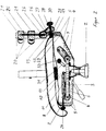
- Figur 2 :
- den erfindungsgemäßen Stuhl gemäß Figur 1 im Teilschnitt in der Seitenansicht;
- Figur 3 :
- die Verstelleinheit des erfindungsgemäßen Stuhles in einer weitere Bauform in einer perspektivischen Ansicht schräg von hinten.
Auf einem Sitzrahmen 5 sind die Polsterplatte 8 mit dem Sitzpolster und beidseitig am Sitzrahmen 5 je ein Armstützenträger 12 mit einer Höhenverstellung 13 und einer Armstütze 14 angeordnet.
Diese beidseitig am Sitzrahmen 5 angeordneten Armstützen 14 sind aufgrund ihrer Höhenverstellung 13 teleskopartig höhenverstellbar und ermöglichen eine optimale und gleichzeitig kostengünstige Einstellung der Armstützenhöhe auf jede für die jeweilige Benutzung bequeme Abstützhöhe.
Am Sitzrahmen sind weiterhin ein Drehknopf 24 zur Einstellung der Verstellhärte der Sitzverstellmechanik und ein in einem Langloch 31 der Seitenwange 19 des Sitzrahmens 5 gelagertes Spannelement 32 zur Endlagenbegrenzung der Sitzverstellmechanik angeordnet.
Hinter dem Sitzpolster sind am Sitzrahmen 5 symmetrisch zur Stuhlmittenachse zwei biegeelastische, beispielsweise aus Glasfaserstäben bestehenden Stützelemente 18 angeordnet.
An den biegeelastischen Stützelementen 18 sind einander benachbart beispielsweise aus elastischen Kunststoff (z.B. PUR-Schaumstoff) bestehende Druckfederelemente 20 und sich über die Rückenbreite erstreckende Formelemente 21 abwechselnd übereinander angeordnet.
Die sich über die Rückenbreite erstreckenden Formelemente 21 sind vorzugsweise bereichsweise geometrisch unterschiedlich aufgebaut.
Dadurch kann einer speziellen anatomischen, aber auch einer individuellen ästhetischen Gestaltung Rechnung getragen werden.
In diesen aus Holz bestehenden Formelementen 21 sind, wie in der Figur 1 dargestellt, Polsterelemente 34 eingearbeitet.
Infolge einer speziellen, unterschiedlichen Querschnittsgestaltung der Formelemente 21 wird zudem in allen Verformungszuständen (Verwindung und
Durchbiegung) der Rückenanlage bei gleichzeitiger, elastisch abgestützter Variation des Körperöffnungswinkels eine optimale, anatomiegerechte Sitzhaltung "erzwungen".
Am oberen Formelement 21 ist in dieser Ausführungsform, wie ebenfalls in der Figur 1 dargestellt, eine Kopfstütze 22 befestigt.
In der Figur 2 wurde nun der erfindungsgemäße Stuhl im Teilschnitt in der Seitenansicht dargestellt.
Am freien Ende der Feder 2 ist eine Zwischenplatte 3 angeordnet. An dieser Zwischenplatte 3 sind beidseitig jeweils zwei Führungsrollen 4 angeordnet. Diese Führungsrollen 4 sind vorn in den horizontalen Führungsnuten 6 und hinten in den bogenförmigen Kulissenführungen 7 der Seitenwangen 19 des Sitzrahmens 5 verschiebbar angeordnet.
Die Führungsnuten 6 und die bogenförmigen Kulissenführungen 7 sind von innen jeweils in die Seitenwange 19 des Sitzrahmens 5 eingearbeitet, wobei in einer Seitenwange 19 mit einer Dicke von beispielsweise 24 mm die Führungsnuten 6 und auch die Kulissenführungen 7 beispielsweise etwa 15 mm tief eingearbeitet sind.
Infolge dieser von außen nicht sichtbaren Nuten wird eine Verletzungsgefahr an den Getriebebaugruppen des Stuhles ausgeschlossen.
Auf dem Sitzrahmen 5 ist die Polsterplatte 8 mit dem Sitzpolster angeordnet. Am Sitzrahmen 5 ist zudem ein Vorspannelement 9 befestigt, welches mittels des Drehknopfes 24 betätigt werden kann. Wie im Halbschnitt ersichtlich, ist zwischen dem Vorspannelement 9 und einem an der Zwischenplatte 3 angeordneten Befestigungselement 10 ein Federelement 11 angeordnet. Dadurch ist es möglich den federelastischen Sitzverstellwiderstand optimal auf das jeweilige Körpergewicht einzustellen, wobei infolge der vorliegenden Lösung in jeder beliebigen Sitzposition allein durch die Gewichtsverlagerung im Sitzen eine Variation der Sitzposition derart möglich ist, daß mittels des erfindungsgemäßen Stuhles sowohl beim Zurücklehnen wie auch beim nach vorn über den Schreibtisch beugen stets ein nahezu gleichbleibender Abstand des Körpers von der Schreibtischkante realisiert wird, so daß in jeder beliebigen Sitzposition ein Weiterarbeiten am Schreibtisch ohne das lästige Nachrücken des gesamten Stuhles (zum Schreibtisch hin, bzw. vom Schreibtisch weg) ermöglicht wird.
Hinter dem Sitzpolster sind am Sitzrahmen 5 (bis in die Seitenwangen 19 hinein) symmetrisch zur Stuhlmittenachse zwei Stützelementbefestigungen 17 in Form von Befestigungsbohrungen 23 mit oder ohne Einsteckhülsen angeordnet.
In diesen sind die biegeelastischen, beispielsweise aus Glasfaserstäben bestehenden Stützelemente 18 angeordnet.
An den biegeelastischen Stützelementen 18 sind, wie bereits in den Ausführungen im Zusammenhang mit Figur 1 erwähnt, einander benachbart aus PUR-Schaum-Hülsen bestehende Druckfederelemente 20 und sich über die Rückenbreite erstreckende, bereichsweise gleichartige oder auch unterschiedlich dimensionierte Formelemente 21 abwechselnd übereinander angeordnet.
Die unteren Formelemente 21 sind miteinander mittels eines symmetrisch zur Mitte zwischen den Stützelementen 18 angeordneten biegeelastischen Versteifungselement 26 (siehe auch Figur 1) verbunden, welches an einem zwischen den Stützelementen 18 am Sitzrahmen 5 auf zwei Lagern 15 mittels einer Achse 16 schwenkbar gelagerten Schwenkhebel 27 angeordnet ist.
Am Schwenkhebel 27 ist ein Wegbegrenzungs- / Vorspannelement 28 und am Sitzrahmen 5 ein mit dem Wegbegrenzungs- / Vorspannelement 28 in Wirkverbindung tretender Anschlag 29 angeordnet.
Der Hubweg des Wegbegrenzungs- / Vorspannelementes 28 kann, wie in der Figur 2 dargestellt, gegenüber dem Anschlag am Sitzrahmen 5 mittels eines Verstellelementes 30 eingestellt werden.
Die Anordnung des Stützelementes 18 bewirkt, daß beim Zurücklehnen eine anatomiegerechte, elastische Abstützung des Oberkörpers im Lendenbereich realisiert werden kann, wobei mittels des Verstellelementes 30 zudem die "Härte" der Lendenstütze dem jeweiligen Bedürfnis des Benutzers angepasst werden kann, so daß aufgrund der erfindungsgemäßen Anordnung beim Zurücklehnen eine variable, anatomiegerechte, elastische Abstützung des Oberkörpers im Lendenbereich realisiert wird.
In der Seitenwange 19 des Sitzrahmens 5 befindet sich darüber hinaus ein Langloch 31 in dem verschiebbar, wie in der Figur 1 dargestellt, ein arretierbares Spannelement 32 angeordnet ist.
Mittels diesem verschieb- und arretierbaren Spannelement 32 kann nun das in der Figur 2 dargestellte, im "Arbeitsbereich" der Zwischenplatte 3 am Spannelement 32 angeordnete, Betätigungselement 33 an jeder beliebigen Stelle im Langloch 31 der Seitenwange 19 des Sitzrahmens 5 verspannt werden.
Entsprechend der jeweiligen Arretierung des Spannelementes 32 im Langloch 31 behindert das am Spannelement 32 angeordnete Betätigungselement 33 den "Arbeitsweg" bzw. den "Hub" der Zwischenplatte, so daß die gegenseitige Relativbewegung zwischen der Zwischenplatte 3 und dem Sitzrahmen 5 definiert eingeschränkt wird.
Somit ist es möglich die "Schwenkmechanik" der Sitzfläche in jeder beliebigen Sitzposition in dieser als Endlage zu begrenzen.
Die Figur 3 zeigt die Verstelleinheit des erfindungsgemäßen Stuhles in einer weiteren Bauform in der perspektivischen Ansicht schräg von hinten.
An der Polsterplatte 8 ist das Adapterelement 35 befestigt.
Dieses Adapterelement 35 besteht aus zwei Trägerholmen 36, einem zwischen diesen Trägerholmen 36 angeordneten Verbindungssteg 37 und einem oberhalb der Trägerholme 36 und dem Verbindungssteg 37 angeordnetem Formteil 38.
Die Trägerholme 36 und der Verbindungssteg 37 sind biegesteif mit der Polsterplatte 8 von unten, und das Formteil 38 ist mit der Polsterplatte 8 biegesteif von hinten verbunden.
Zumindest das untere Formelement 21 ist /(aber auch mehrere der unteren Formelemente 21 können miteinander) mittels eines mittig angeordneten biegeelastischen Versteifungselementes 26 mit dem Schwenkhebel 27 verbunden (sein).
Im Adapterelement 35 sind zwei durch das Formteil 38 in die Trägerholme 36 hineinragende Stützelementbefestigungen 17 angeordnet. In diesen sind die biegeelastischen Stützelemente befestigt. Zwischen dem Formteil 38 des Adapterelementes 35 und dem unteren Formelement 21 sind auf den beiden Stützelementen 18 jeweils ein Druckfederelement 20 aufgesteckt. Mittig zwischen den beiden Stützelementen 18 ist auf dem Formteil 38 des Adapterelementes 35 mittels eines Lagers 15 und einer in diesem Lager 15 angeordneten Achse 16 schwenkbar ein Schwenkhebel 27 befestigt. Am Schwenkhebel 27 ist ein Wegbegrenzungs- / Vorspannelement 28 angeordnet. Am Verbindungssteg 37 befindet sich ein mit dem Wegbegrenzungs- /Vorspannelement 28 in Wirkverbindung tretender Anschlag 29.
Mittels der Variation des Hubweges / der Vorspannung des Wegbegrenzungs- / Vorspannelementes 28 wird eine auf die Körpergröße und somit auch auf das Körpergewicht individuell einstellbare, anatomiegerechte, auch von der jeweiligen Arbeitshaltung abhängige, optimale, elastische Einstellung der Abstützfunktion ermöglicht, so daß in jeder beliebigen Sitzposition unabhängig von der Sitzflächenstellung eine individuell einstellbare elastisch abgestützte Variation des Körperöffnungswinkels mit elastischer Unterstützung im Lendenbereich bei gleichzeitiger elastisch abgestützter Verdrehung des Rückens gewährleistet werden kann.
An der Sitzplatte 8 sind weiterhin die Armstützenträger 12 und die Sitzmechanik 39 angeordnet.
- 1
- Grundgestell
- 2
- Feder
- 3
- Zwischenplatte
- 4
- Führungsrollen
- 5
- Sitzrahmen
- 6
- Führungsnut
- 7
- Kulissenführung
- 7
- Polsterplatte
- 9
- Vorspannelement
- 10
- Befestigungselement
- 11
- Federelement
- 12
- Armstützenträger
- 13
- Höhenverstellung
- 14
- Armstütze
- 15
- Lager
- 16
- Achse
- 17
- Stützelementbefestigung
- 18
- Stützelement
- 19
- Seitenwange
- 20
- Druckfederelement
- 21
- Formelement
- 22
- Kopfstütze
- 23
- Befestigungsbohrung
- 24
- Drehknopf
- 25
- Laufrollen
- 26
- Versteifungselement
- 27
- Schwenkhebel
- 28
- Wegbegrenzungs- / Vorspannelement
- 29
- Anschlag
- 30
- Verstellelement
- 31
- Langloch
- 32
- Spannelement
- 33
- Betätigungselement
- 34
- Polsterelement
- 35
- Adapterelement
- 36
- Trägerholm
- 37
- Verbindungssteg
- 38
- Formteil
- 39
- Sitzmechanik
Claims (6)
- Stuhl, insbesondere Büro- oder Arbeitsstuhl, mit beweglichem Sitz und beweglicher Rückenlehne, und im rückwärtigen Bereich des Sitzpolsters angeordneter/angeordneten Stützelementbefestigung/en (17) in bzw. an denen jeweils ein biegeelastisches Stützelement (18) befestigt ist, wobei entlang jedes Stützelementes (18) Druckfederelemente (20) und sich über die Rückenbreite erstreckende Formelemente (21) jeweils einander benachbart abwechselnd übereinander angeordnet sind, dadurch gekennzeichnet, daß das untere Formelement (21) /oder mehrere der unteren Formelemente (21) miteinander mittels eines /oder mehrerer symmetrisch zur Mitte angeordneten biegeelastischen / biegeelastischer Versteifungselementes / Versteifungselemente (26) mit einem oder mehreren Schwenkhebel/n (27) verbunden ist/sind, welcher/welche in einem oder mehreren zugehörigen am Sitzrahmen (5) und/oder an einem Adapterelement (35) angeordneten Lagern (15) schwenkbar gelagert ist/sind, wobei sich am jeweiligen Schwenkhebel (27) ein Wegbegrenzungs- / Vorspannelement (28) befindet und am Sitzrahmen (5) bzw. dem Adapterelement (35) ein mit dem Wegbegrenzungs- / Vorspannelement (28) in Wirkverbindung tretender Anschlag (29) angeordnet ist, und daß der Hubweg/ die Vorspannung des jeweiligen Wegbegrenzungs- / Vorspannelementes gegenüber dem Anschlag (29) mittels eines Verstellelementes (30) einstellbar ist.
- Stuhl nach Anspruch 1, dadurch gekennzeichnet, daß das Adapterelement (35) am Sitzrahmen (5) und/oder an der Polsterplatte (8) befestigt ist.
- Stuhl nach Anspruch 1, dadurch gekennzeichnet, daß das Adapterelement (35) aus zwei Trägerholmen (36), einem zwischen diesen Trägerholmen (36) angeordneten Verbindungssteg (37) und einem oberhalb der Trägerholme (36) und dem Verbindungssteg (37) angeordnetem Formteil (38) besteht.
- Stuhl nach Anspruch 1, dadurch gekennzeichnet, dass die Trägerholme (36) und der Verbindungssteg (37) von unten, und das Formteil (38) von hinten biegesteif mit der Polsterplatte (8) verbunden sind.
- Stuhl nach Anspruch 1, dadurch gekennzeichnet, daß die Führungsnut (6) und/ oder die Kulissenführung (7) von innen jeweils in die Seitenwange (19) des Sitzrahmens (5) eingearbeitet sind.
- Stuhl nach Anspruch 1, dadurch gekennzeichnet, daß in der Seitenwange (19) des Sitzrahmens (5) ein Langloch (31) angeordnet ist, in dem ein im Langloch (31) verschiebbar gelagertes, arretierbares Spannelement (32) angeordnet ist, welches mit einem im Bereich der Zwischenplatte (3) am Spannelement (31) angeordneten Betätigungselement (33) auf die Zwischenplatte (3) im verspannten Zustand einwirkt und so die gegenseitige Relativbewegung zwischen der Zwischenplatte (3) und dem Sitzrahmen (5) einschränkt.
Applications Claiming Priority (2)
| Application Number | Priority Date | Filing Date | Title |
|---|---|---|---|
| DE10152560A DE10152560A1 (de) | 2000-10-12 | 2001-10-24 | Stuhl |
| DE10152560 | 2001-10-24 |
Publications (3)
| Publication Number | Publication Date |
|---|---|
| EP1306033A2 EP1306033A2 (de) | 2003-05-02 |
| EP1306033A3 EP1306033A3 (de) | 2004-01-07 |
| EP1306033B1 true EP1306033B1 (de) | 2005-03-02 |
Family
ID=7703618
Family Applications (1)
| Application Number | Title | Priority Date | Filing Date |
|---|---|---|---|
| EP02023419A Expired - Lifetime EP1306033B1 (de) | 2001-10-24 | 2002-10-19 | Stuhl |
Country Status (3)
| Country | Link |
|---|---|
| EP (1) | EP1306033B1 (de) |
| AT (1) | ATE289768T1 (de) |
| DE (2) | DE10152560A1 (de) |
Cited By (1)
| Publication number | Priority date | Publication date | Assignee | Title |
|---|---|---|---|---|
| DE102007018856A1 (de) | 2007-04-20 | 2008-10-23 | BRÜNIG, Matthias | Bewegliche Rückenlehne für einen Stuhl oder Sessel |
Families Citing this family (4)
| Publication number | Priority date | Publication date | Assignee | Title |
|---|---|---|---|---|
| DE10326404B4 (de) * | 2003-06-12 | 2007-09-06 | Automotive Group Ise Innomotive Systems Europe Gmbh | Vorrichtung zum Schutz von Personen bei einem Frontaufprall auf ein Kraftfahrzeug |
| DE202004017110U1 (de) * | 2004-11-05 | 2005-01-20 | Meyra Wilhelm Meyer Gmbh & Co. Kg | Sitz mit einer Sitzfläche und einer Rückenlehne |
| NO325146B1 (no) * | 2006-11-01 | 2008-02-11 | Anders Berget | Stol |
| DE102012109710A1 (de) * | 2012-10-11 | 2014-06-12 | Grammer Ag | Fahrzeugsitz mit veränderbarer Rückenlehnenform |
Family Cites Families (4)
| Publication number | Priority date | Publication date | Assignee | Title |
|---|---|---|---|---|
| US4157203A (en) * | 1977-05-09 | 1979-06-05 | Center For Design Research And Development N.V. | Articulated double back for chairs |
| DE4135948C2 (de) | 1991-10-31 | 1993-12-23 | Rolf Voelkle | Stuhl, insbesondere Bürodrehstuhl |
| DE10050430A1 (de) | 2000-10-12 | 2002-04-18 | Sven Poppel | Stuhl |
| DE20107899U1 (de) * | 2001-05-10 | 2001-07-12 | Sede Ag Klingnau De | Sessel |
-
2001
- 2001-10-24 DE DE10152560A patent/DE10152560A1/de not_active Withdrawn
-
2002
- 2002-10-19 DE DE50202363T patent/DE50202363D1/de not_active Expired - Lifetime
- 2002-10-19 AT AT02023419T patent/ATE289768T1/de not_active IP Right Cessation
- 2002-10-19 EP EP02023419A patent/EP1306033B1/de not_active Expired - Lifetime
Cited By (1)
| Publication number | Priority date | Publication date | Assignee | Title |
|---|---|---|---|---|
| DE102007018856A1 (de) | 2007-04-20 | 2008-10-23 | BRÜNIG, Matthias | Bewegliche Rückenlehne für einen Stuhl oder Sessel |
Also Published As
| Publication number | Publication date |
|---|---|
| EP1306033A2 (de) | 2003-05-02 |
| DE50202363D1 (de) | 2005-04-07 |
| EP1306033A3 (de) | 2004-01-07 |
| DE10152560A1 (de) | 2003-05-08 |
| ATE289768T1 (de) | 2005-03-15 |
Similar Documents
| Publication | Publication Date | Title |
|---|---|---|
| EP2243398B1 (de) | Sitzmöbel | |
| EP0016937A1 (de) | Sitzmöbel | |
| WO2006010552A1 (de) | Sitzmöbel, insbesondere bürostuhl | |
| EP1093737B1 (de) | Stuhl | |
| DE102007044130A1 (de) | Rückenlehne insbesondere eines Bürostuhls | |
| EP2047769B1 (de) | Personensitz mit einer Sitzfederung | |
| EP1306033B1 (de) | Stuhl | |
| EP0419714B1 (de) | Rückenlehne mit einer höhenverstellbaren Lendenlordosen-Unterstützung | |
| WO1996011614A1 (de) | Sitz- und trainingsfläche | |
| DE102004027900B4 (de) | Fahrzeugsitz | |
| DE4424096A1 (de) | Stuhl | |
| DE4236834A1 (en) | Chair with bottom frame and seat surface made of flexible strips - incorporates backrest made of flexible strips, with bar and transverse connection | |
| EP3843588B1 (de) | Rückenlehne, insbesondere für einen sitz | |
| DE102020108491A1 (de) | Höhenverstellbares Nackenstütz-System für einen Gaming-Stuhl | |
| DE102006008234B4 (de) | Konturadaptiver Fahrzeugsitz | |
| DE10050430A1 (de) | Stuhl | |
| DE102018122906A1 (de) | Rückenlehne, insbesondere für einen Sitz | |
| EP2689692A1 (de) | Sitzmöbel, insbesondere Bürostuhl | |
| DE202008016707U1 (de) | Sitzmöbel | |
| DE102005044488B4 (de) | Sitzmöbel | |
| DE202007006432U1 (de) | Sitzmöbel mit schwenkbarer Rückenlehne | |
| DE10043347B4 (de) | Fahrzeugsitz mit einem integrierten Kindersitz | |
| DE4027730A1 (de) | Sitzmoebel | |
| EP2807955B1 (de) | Sitzmöbel | |
| DE202021102630U1 (de) | Sitzmöbel |
Legal Events
| Date | Code | Title | Description |
|---|---|---|---|
| PUAI | Public reference made under article 153(3) epc to a published international application that has entered the european phase |
Free format text: ORIGINAL CODE: 0009012 |
|
| AK | Designated contracting states |
Designated state(s): AT BE BG CH CY CZ DE DK EE ES FI FR GB GR IE IT LI LU MC NL PT SE SK TR |
|
| AX | Request for extension of the european patent |
Extension state: AL LT LV MK RO SI |
|
| PUAL | Search report despatched |
Free format text: ORIGINAL CODE: 0009013 |
|
| AK | Designated contracting states |
Kind code of ref document: A3 Designated state(s): AT BE BG CH CY CZ DE DK EE ES FI FR GB GR IE IT LI LU MC NL PT SE SK TR |
|
| AX | Request for extension of the european patent |
Extension state: AL LT LV MK RO SI |
|
| RIC1 | Information provided on ipc code assigned before grant |
Ipc: 7A 47C 7/44 A Ipc: 7A 47C 7/46 B |
|
| 17P | Request for examination filed |
Effective date: 20040527 |
|
| GRAP | Despatch of communication of intention to grant a patent |
Free format text: ORIGINAL CODE: EPIDOSNIGR1 |
|
| AKX | Designation fees paid |
Designated state(s): AT BE BG CH CY CZ DE DK EE ES FI FR GB GR IE IT LI LU MC NL PT SE SK TR |
|
| GRAS | Grant fee paid |
Free format text: ORIGINAL CODE: EPIDOSNIGR3 |
|
| GRAA | (expected) grant |
Free format text: ORIGINAL CODE: 0009210 |
|
| AK | Designated contracting states |
Kind code of ref document: B1 Designated state(s): AT BE BG CH CY CZ DE DK EE ES FI FR GB GR IE IT LI LU MC NL PT SE SK TR |
|
| PG25 | Lapsed in a contracting state [announced via postgrant information from national office to epo] |
Ref country code: IT Free format text: LAPSE BECAUSE OF FAILURE TO SUBMIT A TRANSLATION OF THE DESCRIPTION OR TO PAY THE FEE WITHIN THE PRESCRIBED TIME-LIMIT;WARNING: LAPSES OF ITALIAN PATENTS WITH EFFECTIVE DATE BEFORE 2007 MAY HAVE OCCURRED AT ANY TIME BEFORE 2007. THE CORRECT EFFECTIVE DATE MAY BE DIFFERENT FROM THE ONE RECORDED. Effective date: 20050302 Ref country code: NL Free format text: LAPSE BECAUSE OF FAILURE TO SUBMIT A TRANSLATION OF THE DESCRIPTION OR TO PAY THE FEE WITHIN THE PRESCRIBED TIME-LIMIT Effective date: 20050302 Ref country code: FR Free format text: LAPSE BECAUSE OF NON-PAYMENT OF DUE FEES Effective date: 20050302 Ref country code: CZ Free format text: LAPSE BECAUSE OF FAILURE TO SUBMIT A TRANSLATION OF THE DESCRIPTION OR TO PAY THE FEE WITHIN THE PRESCRIBED TIME-LIMIT Effective date: 20050302 Ref country code: FI Free format text: LAPSE BECAUSE OF FAILURE TO SUBMIT A TRANSLATION OF THE DESCRIPTION OR TO PAY THE FEE WITHIN THE PRESCRIBED TIME-LIMIT Effective date: 20050302 Ref country code: SK Free format text: LAPSE BECAUSE OF FAILURE TO SUBMIT A TRANSLATION OF THE DESCRIPTION OR TO PAY THE FEE WITHIN THE PRESCRIBED TIME-LIMIT Effective date: 20050302 Ref country code: EE Free format text: LAPSE BECAUSE OF FAILURE TO SUBMIT A TRANSLATION OF THE DESCRIPTION OR TO PAY THE FEE WITHIN THE PRESCRIBED TIME-LIMIT Effective date: 20050302 Ref country code: IE Free format text: LAPSE BECAUSE OF FAILURE TO SUBMIT A TRANSLATION OF THE DESCRIPTION OR TO PAY THE FEE WITHIN THE PRESCRIBED TIME-LIMIT Effective date: 20050302 Ref country code: TR Free format text: LAPSE BECAUSE OF FAILURE TO SUBMIT A TRANSLATION OF THE DESCRIPTION OR TO PAY THE FEE WITHIN THE PRESCRIBED TIME-LIMIT Effective date: 20050302 |
|
| REG | Reference to a national code |
Ref country code: GB Ref legal event code: FG4D Free format text: NOT ENGLISH |
|
| REG | Reference to a national code |
Ref country code: CH Ref legal event code: EP |
|
| REG | Reference to a national code |
Ref country code: IE Ref legal event code: FG4D Free format text: GERMAN |
|
| REF | Corresponds to: |
Ref document number: 50202363 Country of ref document: DE Date of ref document: 20050407 Kind code of ref document: P |
|
| PG25 | Lapsed in a contracting state [announced via postgrant information from national office to epo] |
Ref country code: DK Free format text: LAPSE BECAUSE OF FAILURE TO SUBMIT A TRANSLATION OF THE DESCRIPTION OR TO PAY THE FEE WITHIN THE PRESCRIBED TIME-LIMIT Effective date: 20050602 Ref country code: BG Free format text: LAPSE BECAUSE OF FAILURE TO SUBMIT A TRANSLATION OF THE DESCRIPTION OR TO PAY THE FEE WITHIN THE PRESCRIBED TIME-LIMIT Effective date: 20050602 Ref country code: GR Free format text: LAPSE BECAUSE OF FAILURE TO SUBMIT A TRANSLATION OF THE DESCRIPTION OR TO PAY THE FEE WITHIN THE PRESCRIBED TIME-LIMIT Effective date: 20050602 |
|
| PG25 | Lapsed in a contracting state [announced via postgrant information from national office to epo] |
Ref country code: ES Free format text: LAPSE BECAUSE OF FAILURE TO SUBMIT A TRANSLATION OF THE DESCRIPTION OR TO PAY THE FEE WITHIN THE PRESCRIBED TIME-LIMIT Effective date: 20050613 |
|
| GBT | Gb: translation of ep patent filed (gb section 77(6)(a)/1977) |
Effective date: 20050622 |
|
| NLV1 | Nl: lapsed or annulled due to failure to fulfill the requirements of art. 29p and 29m of the patents act | ||
| PG25 | Lapsed in a contracting state [announced via postgrant information from national office to epo] |
Ref country code: PT Free format text: LAPSE BECAUSE OF FAILURE TO SUBMIT A TRANSLATION OF THE DESCRIPTION OR TO PAY THE FEE WITHIN THE PRESCRIBED TIME-LIMIT Effective date: 20050907 |
|
| PG25 | Lapsed in a contracting state [announced via postgrant information from national office to epo] |
Ref country code: CY Free format text: LAPSE BECAUSE OF FAILURE TO SUBMIT A TRANSLATION OF THE DESCRIPTION OR TO PAY THE FEE WITHIN THE PRESCRIBED TIME-LIMIT Effective date: 20051019 |
|
| REG | Reference to a national code |
Ref country code: IE Ref legal event code: FD4D |
|
| PG25 | Lapsed in a contracting state [announced via postgrant information from national office to epo] |
Ref country code: MC Free format text: LAPSE BECAUSE OF NON-PAYMENT OF DUE FEES Effective date: 20051031 |
|
| PLBE | No opposition filed within time limit |
Free format text: ORIGINAL CODE: 0009261 |
|
| STAA | Information on the status of an ep patent application or granted ep patent |
Free format text: STATUS: NO OPPOSITION FILED WITHIN TIME LIMIT |
|
| 26N | No opposition filed |
Effective date: 20051205 |
|
| EN | Fr: translation not filed | ||
| PGFP | Annual fee paid to national office [announced via postgrant information from national office to epo] |
Ref country code: BE Payment date: 20061030 Year of fee payment: 5 |
|
| PG25 | Lapsed in a contracting state [announced via postgrant information from national office to epo] |
Ref country code: SE Free format text: LAPSE BECAUSE OF FAILURE TO SUBMIT A TRANSLATION OF THE DESCRIPTION OR TO PAY THE FEE WITHIN THE PRESCRIBED TIME-LIMIT Effective date: 20050602 |
|
| PGFP | Annual fee paid to national office [announced via postgrant information from national office to epo] |
Ref country code: LU Payment date: 20071105 Year of fee payment: 6 |
|
| BERE | Be: lapsed |
Owner name: *POPPEL SVEN Effective date: 20071031 |
|
| PG25 | Lapsed in a contracting state [announced via postgrant information from national office to epo] |
Ref country code: BE Free format text: LAPSE BECAUSE OF NON-PAYMENT OF DUE FEES Effective date: 20071031 |
|
| PGFP | Annual fee paid to national office [announced via postgrant information from national office to epo] |
Ref country code: AT Payment date: 20090330 Year of fee payment: 7 |
|
| PGFP | Annual fee paid to national office [announced via postgrant information from national office to epo] |
Ref country code: CH Payment date: 20090401 Year of fee payment: 7 |
|
| PGFP | Annual fee paid to national office [announced via postgrant information from national office to epo] |
Ref country code: GB Payment date: 20090427 Year of fee payment: 7 |
|
| REG | Reference to a national code |
Ref country code: CH Ref legal event code: PL |
|
| PG25 | Lapsed in a contracting state [announced via postgrant information from national office to epo] |
Ref country code: LU Free format text: LAPSE BECAUSE OF NON-PAYMENT OF DUE FEES Effective date: 20081019 |
|
| PG25 | Lapsed in a contracting state [announced via postgrant information from national office to epo] |
Ref country code: AT Free format text: LAPSE BECAUSE OF NON-PAYMENT OF DUE FEES Effective date: 20091019 |
|
| PG25 | Lapsed in a contracting state [announced via postgrant information from national office to epo] |
Ref country code: LI Free format text: LAPSE BECAUSE OF NON-PAYMENT OF DUE FEES Effective date: 20091031 Ref country code: CH Free format text: LAPSE BECAUSE OF NON-PAYMENT OF DUE FEES Effective date: 20091031 |
|
| PG25 | Lapsed in a contracting state [announced via postgrant information from national office to epo] |
Ref country code: GB Free format text: LAPSE BECAUSE OF NON-PAYMENT OF DUE FEES Effective date: 20091019 |
|
| REG | Reference to a national code |
Ref country code: DE Ref legal event code: R119 Ref document number: 50202363 Country of ref document: DE |
|
| REG | Reference to a national code |
Ref country code: DE Ref legal event code: R082 Ref document number: 50202363 Country of ref document: DE |
|
| REG | Reference to a national code |
Ref country code: DE Ref legal event code: R073 Ref document number: 50202363 Country of ref document: DE |
|
| PG25 | Lapsed in a contracting state [announced via postgrant information from national office to epo] |
Ref country code: DE Free format text: LAPSE BECAUSE OF NON-PAYMENT OF DUE FEES Effective date: 20130501 |
|
| REG | Reference to a national code |
Ref country code: DE Ref legal event code: R119 Ref document number: 50202363 Country of ref document: DE Effective date: 20130501 |
|
| REG | Reference to a national code |
Ref country code: DE Ref legal event code: R074 Ref document number: 50202363 Country of ref document: DE |
|
| REG | Reference to a national code |
Ref country code: DE Ref legal event code: R074 Ref document number: 50202363 Country of ref document: DE Effective date: 20130904 Ref country code: DE Ref legal event code: R074 Ref document number: 50202363 Country of ref document: DE Effective date: 20130907 |
|
| PGRI | Patent reinstated in contracting state [announced from national office to epo] |
Ref country code: DE Effective date: 20130904 |
|
| PGFP | Annual fee paid to national office [announced via postgrant information from national office to epo] |
Ref country code: DE Payment date: 20160309 Year of fee payment: 14 |
|
| REG | Reference to a national code |
Ref country code: DE Ref legal event code: R119 Ref document number: 50202363 Country of ref document: DE |
|
| PG25 | Lapsed in a contracting state [announced via postgrant information from national office to epo] |
Ref country code: DE Free format text: LAPSE BECAUSE OF NON-PAYMENT OF DUE FEES Effective date: 20170503 |