EP1304494A1 - Lamellenkupplung für Motorräder - Google Patents
Lamellenkupplung für Motorräder Download PDFInfo
- Publication number
- EP1304494A1 EP1304494A1 EP02019630A EP02019630A EP1304494A1 EP 1304494 A1 EP1304494 A1 EP 1304494A1 EP 02019630 A EP02019630 A EP 02019630A EP 02019630 A EP02019630 A EP 02019630A EP 1304494 A1 EP1304494 A1 EP 1304494A1
- Authority
- EP
- European Patent Office
- Prior art keywords
- plate
- clutch according
- clutch
- plunger
- valve
- Prior art date
- Legal status (The legal status is an assumption and is not a legal conclusion. Google has not performed a legal analysis and makes no representation as to the accuracy of the status listed.)
- Granted
Links
- 239000003921 oil Substances 0.000 claims description 50
- 238000010168 coupling process Methods 0.000 claims description 18
- 230000008878 coupling Effects 0.000 claims description 17
- 238000005859 coupling reaction Methods 0.000 claims description 17
- 238000003825 pressing Methods 0.000 claims description 3
- 239000010705 motor oil Substances 0.000 claims description 2
- 239000012530 fluid Substances 0.000 claims 1
- 238000006073 displacement reaction Methods 0.000 description 3
- 239000002826 coolant Substances 0.000 description 2
- 238000001816 cooling Methods 0.000 description 2
- 239000000314 lubricant Substances 0.000 description 2
- 241000446313 Lamella Species 0.000 description 1
- 238000009825 accumulation Methods 0.000 description 1
- 230000003044 adaptive effect Effects 0.000 description 1
- 230000005540 biological transmission Effects 0.000 description 1
- 238000010276 construction Methods 0.000 description 1
- 238000013016 damping Methods 0.000 description 1
- 238000011161 development Methods 0.000 description 1
- 230000018109 developmental process Effects 0.000 description 1
- 238000007599 discharging Methods 0.000 description 1
- 230000017525 heat dissipation Effects 0.000 description 1
- 239000010687 lubricating oil Substances 0.000 description 1
- 238000005461 lubrication Methods 0.000 description 1
- 230000001105 regulatory effect Effects 0.000 description 1
- 230000008646 thermal stress Effects 0.000 description 1
Images


Classifications
-
- F—MECHANICAL ENGINEERING; LIGHTING; HEATING; WEAPONS; BLASTING
- F16—ENGINEERING ELEMENTS AND UNITS; GENERAL MEASURES FOR PRODUCING AND MAINTAINING EFFECTIVE FUNCTIONING OF MACHINES OR INSTALLATIONS; THERMAL INSULATION IN GENERAL
- F16D—COUPLINGS FOR TRANSMITTING ROTATION; CLUTCHES; BRAKES
- F16D13/00—Friction clutches
- F16D13/22—Friction clutches with axially-movable clutching members
- F16D13/38—Friction clutches with axially-movable clutching members with flat clutching surfaces, e.g. discs
- F16D13/52—Clutches with multiple lamellae ; Clutches in which three or more axially moveable members are fixed alternately to the shafts to be coupled and are pressed from one side towards an axially-located member
-
- F—MECHANICAL ENGINEERING; LIGHTING; HEATING; WEAPONS; BLASTING
- F16—ENGINEERING ELEMENTS AND UNITS; GENERAL MEASURES FOR PRODUCING AND MAINTAINING EFFECTIVE FUNCTIONING OF MACHINES OR INSTALLATIONS; THERMAL INSULATION IN GENERAL
- F16D—COUPLINGS FOR TRANSMITTING ROTATION; CLUTCHES; BRAKES
- F16D13/00—Friction clutches
- F16D13/58—Details
- F16D13/74—Features relating to lubrication
Definitions
- the present invention relates to a multi-plate clutch according to the preamble of claim 1
- Such a multi-plate clutch is known from DE 199 37 440 C1.
- This multi-plate clutch has a arranged in a clutch housing Lamella package on, with part of the slats on a plate carrier is arranged, the fixed with a hollow cylindrical coupling shaft connected is.
- the hollow cylindrical coupling shaft serves on the one hand for Transmission of the clutch torque and additionally as "oil line”.
- the Clutch shaft opens into the interior of the clutch housing and supplies the disk pack as well as various bearings with oil.
- the oil serves as a lubricant and as a cooling medium. In coupling processes arises namely at the fins frictional heat most of the oil must be dissipated.
- the object of the invention is to provide a multi-plate clutch, the one higher overall efficiency.
- the basic principle of the invention is that for lubrication and Cooling of the multi-plate clutch serving oil volume flow as needed to control or regulate.
- a "control device” is provided, which controls the oil volume flow allows.
- the oil volume flow can thus be "started up” if a large Heat dissipation is dissipate, especially in the clutch actuation, i.e. during engagement or disengagement. With the clutch closed however, the heat accumulation is comparatively low. Thus, at closed clutch oil flow are kept low. This Above all, has the advantage that the churning losses in the Reduce multi-plate clutch and thus improves the overall efficiency.
- control device a device for varying the flow cross section of the oil circuit the multi-plate clutch.
- valve In a first variant of the invention is inside the hollow cylindrical Coupling shaft arranged a "valve" whose flow cross-section in dependence the coupling state, i. depending on the position the coupling is variable.
- the valve can be structurally very simple be constructed, namely by a fixed in the hollow cylindrical shaft arranged aperture and a cooperating needle or a cooperating axially displaceable plunger. By axial Moving the needle or the plunger, the flow cross-section of the Valve continuously changed.
- the plunger tip is for this purpose preferably designed conical.
- the valve is wide open, i.e. the plunger tip is located at a relatively large distance from the aperture.
- the plunger tip moved relatively close to the aperture, resulting in a close Flow cross section and thus relatively low oil flow results.
- the needle or the plunger is mechanically connected to the "disengaging element" connected to the multi-plate clutch. That is, when pressing the Multi-plate clutch via the disengagement element, the plunger is “automatically” moved. It is structurally simple, if the plunger as a pin-like Extension of the releaser of the coupling is formed.
- control device is by a "outside" of the multi-plate clutch and the clutch shaft arranged Valve formed.
- this valve is between the oil pump and arranged the coupling shaft.
- the valve can, for example, electrically be controllable.
- Figure 1 shows a multi-plate clutch 1 with a plate pack 2.
- a first Part of the fins is arranged on a plate carrier 3, which with a Sprocket carrier 4 is connected.
- the plate carrier 3 is connected to the toothed rim carrier 4 elastically damping by spring elements 5 in the circumferential direction coupled and rotatably supported by a needle bearing 6 on a sleeve 7, the is arranged on a hollow cylindrical coupling shaft 8.
- a second Disk carrier 9 is rotatably on a spline 10 on the Coupling shaft 8 is arranged and in the axial direction by a shaft nut 11 fixed.
- a pressure plate 12 is provided, which via pressure springs 13 with the plate carrier 9 is braced and the ball bearing 14 with a axially displaceable disengaging element 15 is connected.
- the pressure springs 13 press the pressure plate 12 against the plate carrier 9. This will be compressed the individual slats of the plate pack 2, which is the engaged state of the multi-plate clutch 1 corresponds.
- the multi-plate clutch 1 is over a hollow cylindrical interior 16 of the clutch shaft 8 supplied with oil.
- the oil serves as a lubricant for the multi-plate clutch and various bearings.
- the oil serves as a coolant for discharging the in Disc pack 2 resulting frictional heat output.
- the hollow cylindrical clutch shaft 8 From the hollow cylindrical interior 16 branch off transversely stub lines 17, supply the nail bearing 6 with lubricating oil. Furthermore, in the hollow cylindrical clutch shaft 8 a “valve” is provided, the one Control of the interior 16 in the multi-plate clutch 1 flowing Oil volume flow allows.
- the "valve” consists of a fixed in the Clutch shaft 8 arranged aperture 18 and a mandrel-like plunger 19, which is formed as an extension of the release element 15.
- Figures 2 and 3 show the aperture 18 and the plunger 19 in the region of the plunger tip 20 in two different positions.
- the plunger 19 is in its left end position, which corresponds to a relatively small flow area and a small oil flow rate.
- the plunger 19 is in a right-hand position, which corresponds to a larger flow cross-section and thus to a larger oil volume flow.
- the plunger is conically pointed in the region of the plunger tip 20, so that the flow cross-section is relatively continuously "adjustable" by axial displacement of the plunger 19, at least in a certain displacement range.
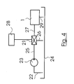
- FIG 4 shows a schematic representation of a variant of the invention, in which an "adjustment" 21 is disposed outside of the multi-plate clutch 1.
- an oil pump 23 Via an intake line 22, an oil pump 23 sucks oil from an oil reservoir 24 and pumps the oil via a line 25 to the adjustment valve 21, which is here a three-way valve.
- the adjustment valve 21 is connected via a return line 26 to the oil reservoir 24 and via an oil line 27 with the multi-plate clutch 1.
- the adjustment valve 21 is electrically controlled by an electronic control unit 28.
- the supplied via the line 25 oil flow is now divided according to the position of the adjusting valve 21 on the lines 26 and 27 respectively.
- the oil flow flows via a return line 29 into the oil tank 24 back.
- the oil volume flow in the multi-plate clutch 1 can be regulated as needed.
Landscapes
- Engineering & Computer Science (AREA)
- General Engineering & Computer Science (AREA)
- Mechanical Engineering (AREA)
- Hydraulic Clutches, Magnetic Clutches, Fluid Clutches, And Fluid Joints (AREA)
Abstract
Description
- Figur 1
- einen Querschnitt durch eine Lamellenkupplung gemäß der Erfindung;
- Figuren 2, 3
- zwei verschiedene Stellungen eines in die Kupplungswelle integrierten Ventils der Lamellenkupplung der Figur 1; und
- Figur 4
- eine schematische Darstellung eines "außerhalb" der Lamellenkupplung angeordneten elektrisch ansteuerbaren Ventils.
Claims (14)
- Lamellenkupplung für Motorräder mit
einer hohlzylindrischen Kupplungswelle, deren hohlzylindrischer Innenraum eine Ölleitung ist, die mit einem Innenraum eines Kupplungsgehäuses in Fluidverbindung steht,
dadurch gekennzeichnet, dass eine Steuereinrichtung (18, 19, 21) zur Steuerung des in der Kupplungswelle (8) strömenden Ölvolumenstroms vorgesehen ist. - Lamellenkupplung nach Anspruch 1,
dadurch gekennzeichnet, dass die Steuereinrichtung (18, 19, 21) eine Einrichtung zur Variierung des Durchflussquerschnitts ist. - Lamellenkupplung nach Anspruch 1 oder 2,
dadurch gekennzeichnet, dass die Steuereinrichtung (18, 19, 21) ein Ventil aufweist, das im Innenraum (16) der hohlzylindrischen Kupplungswelle (8) angeordnet ist. - Lamellenkupplung nach einem der Ansprüche 1 bis 3,
dadurch gekennzeichnet, dass im Innenraum (16) der hohlzylindrischen Kupplungswelle (8) eine Blende (18) und koaxial zu einer Öffnung der Blende (18) ein nadelartiger Stößel (19) angeordnet ist. - Lamellenkupplung nach Anspruch 4,
dadurch gekennzeichnet, dass der Stößel (18, 19) eine konische Stößelspitze (20) aufweist. - Lamellenkupplung nach einem der Ansprüche 4 oder 5,
dadurch gekennzeichnet, dass die Blende (18) fest im Innenraum (16) der Kupplungswelle (8) angeordnet ist und dass der Stößel (19) axial verschieblich bezüglich der Blende (18) ist. - Lamellenkupplung nach einem der Ansprüche 4 bis 6,
dadurch gekennzeichnet, dass der Stößel (19) mit einem axial beweglichen Ausrückelement (15) der Lamellenkupplung (1) verbunden ist. - Lamellenkupplung nach einem der Ansprüche 4 bis 7,
dadurch gekennzeichnet, dass sich der Stößel (19) im eingekuppelten Zustand der Lamellenkupplung (1) in einer an die Blende (18) herangerückten Stellung befindet und im ausgekuppelten Zustand in einer von der Blende (18) weggerückten Stellung. - Lamellenkupplung nach einem der Ansprüche 1 bis 8,
dadurch gekennzeichnet, dass die Lamellenkupplung (1) von einer Motorölpumpe (23) mit Öl versorgt wird. - Lamellenkupplung nach einem der Ansprüche 1, 2 oder 9,
dadurch gekennzeichnet, dass die Steuereinrichtung ein außerhalb der Kupplungswelle angeordnetes Ventil (21) aufweist. - Lamellenkupplung nach Anspruch 10,
dadurch gekennzeichnet, dass das Ventil (21) ein elektrisch ansteuerbares Ventil ist. - Lamellenkupplung nach einem der Ansprüche 10 oder 11,
dadurch gekennzeichnet, dass das Ventil (21) zwischen der Ölpumpe (23) und der Lamellenkupplung (1) angeordnet ist. - Lamellenkupplung nach einem der Ansprüche 10 bis 12,
dadurch gekennzeichnet, dass das Ventil (21) ein Dreiwegeventil ist. - Lamellenkupplung nach einem der Ansprüche 1 bis 13,
dadurch gekennzeichnet, dass die Lamellenkupplung (1) einen ersten Lamellen zugeordneten ersten Lamellenträger (3) aufweist, der über eine Keilverzahnung (10) drehfest mit der Kupplungswelle (8) verbunden ist, und einen zweiten Lamellen zugeordneten zweiten Lamellenträger (9) und dass ein Anpreßelement (12) vorgesehen ist, das durch Anpressfedern (13) mit dem zweiten Lamellenträger (9) verspannt ist, wobei das Anpresselement (12) mittels eines Ausrückelements (15) ausrückbar ist.
Applications Claiming Priority (2)
| Application Number | Priority Date | Filing Date | Title |
|---|---|---|---|
| DE10150704A DE10150704A1 (de) | 2001-10-13 | 2001-10-13 | Lamellenkupplung, insbesondere für Motorräder |
| DE10150704 | 2001-10-13 |
Publications (2)
| Publication Number | Publication Date |
|---|---|
| EP1304494A1 true EP1304494A1 (de) | 2003-04-23 |
| EP1304494B1 EP1304494B1 (de) | 2004-06-02 |
Family
ID=7702477
Family Applications (1)
| Application Number | Title | Priority Date | Filing Date |
|---|---|---|---|
| EP02019630A Expired - Lifetime EP1304494B1 (de) | 2001-10-13 | 2002-09-03 | Lamellenkupplung für Motorräder |
Country Status (2)
| Country | Link |
|---|---|
| EP (1) | EP1304494B1 (de) |
| DE (2) | DE10150704A1 (de) |
Cited By (2)
| Publication number | Priority date | Publication date | Assignee | Title |
|---|---|---|---|---|
| WO2005119077A1 (de) * | 2004-06-03 | 2005-12-15 | Zf Friedrichshafen Ag | Nasslaufende lamellenkupplung |
| WO2013056905A1 (de) * | 2011-10-17 | 2013-04-25 | Zf Friedrichshafen Ag | Vorrichtung zur steuerung eines kühl- und/oder schmierölstromes |
Families Citing this family (3)
| Publication number | Priority date | Publication date | Assignee | Title |
|---|---|---|---|---|
| DE102004021417B4 (de) * | 2004-04-30 | 2014-01-23 | Bayerische Motoren Werke Aktiengesellschaft | Ölversorgung für eine Lamellenkupplung |
| EP3354920B1 (de) | 2017-01-31 | 2019-12-11 | GKN Driveline Bruneck AG | Kupplungsanordnung für einen antriebsstrang und getriebeanordnung mit einer solchen kupplungsanordnung |
| DE102022201805A1 (de) | 2022-02-22 | 2023-08-24 | Zf Friedrichshafen Ag | Kupplung mit einer Kühlvorrichtung sowie Antriebsstrang mit einer solchen Kupplung |
Citations (4)
| Publication number | Priority date | Publication date | Assignee | Title |
|---|---|---|---|---|
| JPS58102827A (ja) * | 1982-07-23 | 1983-06-18 | Honda Motor Co Ltd | 油圧作動式摩擦クラツチの冷却油量調節装置 |
| US4601375A (en) * | 1982-07-06 | 1986-07-22 | Honda Giken Kogyo Kabushiki Kaisha | Clutch apparatus for vehicles |
| JPS61165029A (ja) * | 1985-01-12 | 1986-07-25 | Honda Motor Co Ltd | 油圧式多板クラツチ |
| JPH0473429A (ja) * | 1990-07-13 | 1992-03-09 | Suzuki Motor Corp | クラッチ操作倍力装置 |
Family Cites Families (2)
| Publication number | Priority date | Publication date | Assignee | Title |
|---|---|---|---|---|
| AT389157B (de) * | 1988-07-06 | 1989-10-25 | Steyr Daimler Puch Ag | Einrichtung zur schmier- und kuehlmittelversorgung einer unter last schaltbaren kupplung eines kraftfahrzeuggetriebes |
| DE19937440C1 (de) * | 1999-08-07 | 2001-05-23 | Porsche Ag | Schmiervorrichtung für eine Lamellenkupplung |
-
2001
- 2001-10-13 DE DE10150704A patent/DE10150704A1/de not_active Withdrawn
-
2002
- 2002-09-03 EP EP02019630A patent/EP1304494B1/de not_active Expired - Lifetime
- 2002-09-03 DE DE50200498T patent/DE50200498D1/de not_active Expired - Lifetime
Patent Citations (4)
| Publication number | Priority date | Publication date | Assignee | Title |
|---|---|---|---|---|
| US4601375A (en) * | 1982-07-06 | 1986-07-22 | Honda Giken Kogyo Kabushiki Kaisha | Clutch apparatus for vehicles |
| JPS58102827A (ja) * | 1982-07-23 | 1983-06-18 | Honda Motor Co Ltd | 油圧作動式摩擦クラツチの冷却油量調節装置 |
| JPS61165029A (ja) * | 1985-01-12 | 1986-07-25 | Honda Motor Co Ltd | 油圧式多板クラツチ |
| JPH0473429A (ja) * | 1990-07-13 | 1992-03-09 | Suzuki Motor Corp | クラッチ操作倍力装置 |
Non-Patent Citations (3)
| Title |
|---|
| PATENT ABSTRACTS OF JAPAN vol. 007, no. 207 (M - 242) 13 September 1983 (1983-09-13) * |
| PATENT ABSTRACTS OF JAPAN vol. 010, no. 372 (M - 544) 11 December 1986 (1986-12-11) * |
| PATENT ABSTRACTS OF JAPAN vol. 016, no. 284 (M - 1270) 24 June 1992 (1992-06-24) * |
Cited By (5)
| Publication number | Priority date | Publication date | Assignee | Title |
|---|---|---|---|---|
| WO2005119077A1 (de) * | 2004-06-03 | 2005-12-15 | Zf Friedrichshafen Ag | Nasslaufende lamellenkupplung |
| WO2013056905A1 (de) * | 2011-10-17 | 2013-04-25 | Zf Friedrichshafen Ag | Vorrichtung zur steuerung eines kühl- und/oder schmierölstromes |
| CN103890434A (zh) * | 2011-10-17 | 2014-06-25 | Zf腓德烈斯哈芬股份公司 | 用于控制冷却油流和/或润滑油流的装置 |
| US9470329B2 (en) | 2011-10-17 | 2016-10-18 | Zf Friedrichshafen Ag | Device for controlling a flow of coolant and/or lubricating oil |
| CN103890434B (zh) * | 2011-10-17 | 2017-04-26 | Zf腓德烈斯哈芬股份公司 | 用于控制冷却油流和/或润滑油流的装置 |
Also Published As
| Publication number | Publication date |
|---|---|
| EP1304494B1 (de) | 2004-06-02 |
| DE10150704A1 (de) | 2003-04-17 |
| DE50200498D1 (de) | 2004-07-08 |
Similar Documents
| Publication | Publication Date | Title |
|---|---|---|
| DE2818591C2 (de) | Druckmittelbetätigbare Reibscheibenkupplung | |
| EP2035267B1 (de) | Hydrodynamischer retarder | |
| EP1446590B2 (de) | Antriebsstrang für ein kraftfahrzeug | |
| EP0787929B1 (de) | Vorrichtung zur Temperierung des Getriebeöls eines Kraftfahrzeuges | |
| DE3927153C2 (de) | Temperaturgesteuerte Ventilatorflüssigkeitsreibungskupplung | |
| EP2586641B1 (de) | Zapfwellengetriebe | |
| WO2008028559A2 (de) | Thermostatisches ventil zur regelung eines massenstromes | |
| EP1420186A2 (de) | Kraftfahrzeug- Antriebsstrang mit einer Pumpenanordnung zur Versorgung einer Kupplungseinrichtung mit Druckmedium | |
| DE112007002419T5 (de) | Fluidzufuhrgerät | |
| DE102004012117B4 (de) | Kupplungsvorrichtung | |
| DE102014207280B4 (de) | Ventil für ein Kühlsystem eines Kraftfahrzeugs mit verringertem Energieverbrauch | |
| EP3622191B1 (de) | Schalteinheit für kühlöl und hybridmodul mit schalteinheit | |
| DE102009001264A1 (de) | Ölkühlkreislauf eines Kraftfahrzeuggetriebes mit Wegeventil | |
| DE3622335C2 (de) | Antriebseinrichtung für Nebenaggregate einer Brennkraftmaschine | |
| EP1304494B1 (de) | Lamellenkupplung für Motorräder | |
| DE102005007685A1 (de) | Kühlölzuführung für ein nasslaufendes Schalt-bzw. Anfahrelement | |
| EP0129685A1 (de) | Flüssigkeitsreibungskupplung | |
| DE102019123982A1 (de) | Elektrofahrzeug mit einem 2-Gang-Getriebe | |
| EP1541887B1 (de) | Vorrichtung zum Kühlen einer Reiblamellenanordnung einer Kupplung | |
| DE4444242B4 (de) | Kupplungsanordnung für ein Kraftfahrzeug | |
| EP1722108B1 (de) | Hydraulische Betätigungseinrichtung eines Kraftfahrzeuges mit einem varaiblen Drosselglied | |
| DE102004027113B4 (de) | Nasslaufende Lamellenkupplung mit regelbarer Schmierung und Kühlung | |
| DE3889608T2 (de) | Temperaturabhängige Durchflussregelvorrichtung. | |
| DE102018202130B4 (de) | Komponente für ein Kraftfahrzeug und Kraftfahrzeug | |
| DE102004021417B4 (de) | Ölversorgung für eine Lamellenkupplung |
Legal Events
| Date | Code | Title | Description |
|---|---|---|---|
| PUAI | Public reference made under article 153(3) epc to a published international application that has entered the european phase |
Free format text: ORIGINAL CODE: 0009012 |
|
| 17P | Request for examination filed |
Effective date: 20030130 |
|
| AK | Designated contracting states |
Designated state(s): AT BE BG CH CY CZ DE DK EE ES FI FR GB GR IE IT LI LU MC NL PT SE SK TR |
|
| AX | Request for extension of the european patent |
Extension state: AL LT LV MK RO SI |
|
| 17Q | First examination report despatched |
Effective date: 20030610 |
|
| GRAP | Despatch of communication of intention to grant a patent |
Free format text: ORIGINAL CODE: EPIDOSNIGR1 |
|
| AKX | Designation fees paid |
Designated state(s): DE FR GB IT |
|
| GRAS | Grant fee paid |
Free format text: ORIGINAL CODE: EPIDOSNIGR3 |
|
| GRAA | (expected) grant |
Free format text: ORIGINAL CODE: 0009210 |
|
| AK | Designated contracting states |
Kind code of ref document: B1 Designated state(s): DE FR GB IT |
|
| REG | Reference to a national code |
Ref country code: GB Ref legal event code: FG4D Free format text: NOT ENGLISH |
|
| GBT | Gb: translation of ep patent filed (gb section 77(6)(a)/1977) |
Effective date: 20040602 |
|
| REF | Corresponds to: |
Ref document number: 50200498 Country of ref document: DE Date of ref document: 20040708 Kind code of ref document: P |
|
| REG | Reference to a national code |
Ref country code: IE Ref legal event code: FG4D Free format text: GERMAN |
|
| ET | Fr: translation filed | ||
| REG | Reference to a national code |
Ref country code: IE Ref legal event code: FD4D |
|
| PLBE | No opposition filed within time limit |
Free format text: ORIGINAL CODE: 0009261 |
|
| STAA | Information on the status of an ep patent application or granted ep patent |
Free format text: STATUS: NO OPPOSITION FILED WITHIN TIME LIMIT |
|
| 26N | No opposition filed |
Effective date: 20050303 |
|
| REG | Reference to a national code |
Ref country code: FR Ref legal event code: PLFP Year of fee payment: 15 |
|
| REG | Reference to a national code |
Ref country code: FR Ref legal event code: PLFP Year of fee payment: 16 |
|
| REG | Reference to a national code |
Ref country code: FR Ref legal event code: PLFP Year of fee payment: 17 |
|
| PGFP | Annual fee paid to national office [announced via postgrant information from national office to epo] |
Ref country code: FR Payment date: 20210927 Year of fee payment: 20 Ref country code: IT Payment date: 20210930 Year of fee payment: 20 |
|
| PGFP | Annual fee paid to national office [announced via postgrant information from national office to epo] |
Ref country code: DE Payment date: 20210904 Year of fee payment: 20 Ref country code: GB Payment date: 20210923 Year of fee payment: 20 |
|
| REG | Reference to a national code |
Ref country code: DE Ref legal event code: R071 Ref document number: 50200498 Country of ref document: DE |
|
| REG | Reference to a national code |
Ref country code: GB Ref legal event code: PE20 Expiry date: 20220902 |
|
| PG25 | Lapsed in a contracting state [announced via postgrant information from national office to epo] |
Ref country code: GB Free format text: LAPSE BECAUSE OF EXPIRATION OF PROTECTION Effective date: 20220902 |
|
| P01 | Opt-out of the competence of the unified patent court (upc) registered |
Effective date: 20230502 |